EP2885580B1 - Allumeur comprenant une flamme pilote monté dans un brûleur à gaz - Google Patents
Allumeur comprenant une flamme pilote monté dans un brûleur à gaz Download PDFInfo
- Publication number
- EP2885580B1 EP2885580B1 EP13732142.8A EP13732142A EP2885580B1 EP 2885580 B1 EP2885580 B1 EP 2885580B1 EP 13732142 A EP13732142 A EP 13732142A EP 2885580 B1 EP2885580 B1 EP 2885580B1
- Authority
- EP
- European Patent Office
- Prior art keywords
- cap
- end portion
- gas
- pilot flame
- flame
- Prior art date
- Legal status (The legal status is an assumption and is not a legal conclusion. Google has not performed a legal analysis and makes no representation as to the accuracy of the status listed.)
- Active
Links
Images


Classifications
-
- F—MECHANICAL ENGINEERING; LIGHTING; HEATING; WEAPONS; BLASTING
- F23—COMBUSTION APPARATUS; COMBUSTION PROCESSES
- F23Q—IGNITION; EXTINGUISHING-DEVICES
- F23Q9/00—Pilot flame igniters
- F23Q9/02—Pilot flame igniters without interlock with main fuel supply
- F23Q9/04—Pilot flame igniters without interlock with main fuel supply for upright burners, e.g. gas-cooker burners
- F23Q9/045—Structurally associated with a main-burner
-
- F—MECHANICAL ENGINEERING; LIGHTING; HEATING; WEAPONS; BLASTING
- F23—COMBUSTION APPARATUS; COMBUSTION PROCESSES
- F23Q—IGNITION; EXTINGUISHING-DEVICES
- F23Q3/00—Igniters using electrically-produced sparks
-
- F—MECHANICAL ENGINEERING; LIGHTING; HEATING; WEAPONS; BLASTING
- F23—COMBUSTION APPARATUS; COMBUSTION PROCESSES
- F23Q—IGNITION; EXTINGUISHING-DEVICES
- F23Q9/00—Pilot flame igniters
- F23Q9/02—Pilot flame igniters without interlock with main fuel supply
- F23Q9/04—Pilot flame igniters without interlock with main fuel supply for upright burners, e.g. gas-cooker burners
Definitions
- the present invention relates to an assembly comprising an igniter with pilot mounted in a gas-fired burner.
- the pilot flame of the secondary burner is ignited manually or by means of a piezoelectric ignition device and the burner proper can also be provided with a thermocouple that detects the presence or absence of the pilot flame. If there is no thermocouple, the pilot flame has the function of simplifying the ignition of the main burner, allowing with a single ignition of the pilot flame (manual or piezoelectric ignition) repeated ignitions of the main burner.
- thermocouple If a thermocouple is associated with the pilot flame, it detects the presence of said flame and keeps open a valve that allows the flow of gas to the main burner. If the pilot flame is extinguished, for example due to a spillage of liquids or to a malfunction, the thermocouple detects a reduction in the temperature and actuates the closure of the valve, thus blocking the delivery of gas to the main burner.
- the pilot flame remains always on except for problems, which the system manages in the manner described above.
- One of the main causes of extinguishing of the pilot flame is the blocking of the orifices of the flame separator of the pilot or of the Venturi tube as a consequence of the deposition of particles of detergents used to clean the burner or of solid particles that deposit over time or due to the spillage of liquids.
- Another possible cause of extinguishing is linked to the air currents that can strike the pilot flame during use of the main burner.
- US 6 139 311 discloses a pilot burner apparatus including a mixer tube with a venturi configuration for expansion of the mixed gases, a pilot gas tube having a nozzle projecting into the mixer tube, an opening at an outer end of the mixer tube arranged in a wall of an air dam, a secondary air shield toward which the orifice of the nozzle points in a downstream direction along a pilot gas tube, and a round aperture positioned in the side of the secondary air shield for permitting the exit of unburned fuel gas, combustion byproducts, and flame.
- the aim of the present invention is to provide an igniter with pilot flame that allows to prevent the accidental extinguishing or failure to operate of the pilot flame.
- an object of the invention is to propose a pilot flame device that can be cleaned easily of the dirt particles that can block the parts crossed by the gas.
- Another object of the invention is to hinder the passage of dirt from the flame separator of the pilot flame to the Venturi tube.
- a further object of the invention is to prevent the extinguishing of the pilot flame as a consequence of air currents.
- an igniter with pilot flame mounted in a gas-fired burner as defined in the appended claims.
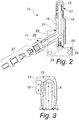
- the device according to the invention generally designated by the reference numeral 10 in the first embodiment, comprises a Venturi tube 11, which ends at the part where the mix of gas and oxidizer exits with a cap 12 that is fitted removably and with play on an end portion 13 thereof.
- a tapering of the end portion 13 causes its dimensions to be small enough with respect to those of the cavity of the cap 12 so that an interspace 15 for the passage of the mix is present between the two.
- Two holes 16 are provided in the cap 12 and are transverse to the end portion 13 for the outflow of the combustible mix and are faced by a thermocouple 17; the pilot flame 18 forms from them.
- the two holes 16, in this embodiment, are mutually aligned in the same longitudinal direction of extension as the end portion 13.
- the cap 12 is fitted so as to rest on an underlying shoulder 14 of the Venturi tube 11 and is thus spaced axially from the end portion 13, creating for the combustible mix a complex path A, i.e., a siphon-shaped path.
- the orientation of the cap 12 with respect to the end portion 13 is such that the pilot flame 18 affects the thermocouple 17 and simultaneously the flow of the combustible mix 22 that exits from the flame separator 30 of the gas-fired burner 29, so as to ignite it.
- thermocouple 17 The device 10 described here is provided with a thermocouple 17; however, in other embodiments the thermocouple might not be present.
- the orientation of the cap 12 is defined by positioning means 31 that are further intended to prevent its rotation with respect to the end portion 13 on which it is fitted.
- the Venturi tube 11 comprises two portions: a first portion 19, at the end 13 of which there is the cap 12, and a second portion 20, by means of which the Venturi tube is associated with a source of gas and extends laterally with respect to an intermediate region 21 of the first portion 19.
- the device 10 is associated with the gas-fired burner 29 so that the first portion 19 is arranged along the vertical direction and therefore said holes 16 are aligned vertically.
- the first portion 19 has, on the opposite side 23 with respect to the exit side of the combustible mix, a removable plug 24.
- the cap 12 is provided with an element 25 for conveying a flame, therefore the pilot flame 18, toward the thermocouple 17, which at the same time protects it against any air currents.
- the device 10 is further provided with means 26 for fixing to the supporting structure and with means 27 for connection to a source of gas from which the gas rises along the Venturi tube 11, entraining the oxidizing air aspirated through the intake holes 28.
- the device 10 can be associated with the gas-fired burner 29, so that the pilot flame 18 is directed toward its flame separator 30, or, as shown in Figure 5 , it can be arranged below the gas-fired burner 29, so that the pilot flame 18 affects the flow of the combustible mix 22 in output from the flame separator 30 of the gas-fired burner 29.
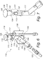
- the device 110 in the second embodiment also comprises a Venturi tube 111 provided, at the part where the combustible mix exits, with a cap 112, here too fitted removably on an end portion 113 of the Venturi tube 111 and rested on the shoulder 114, so as to be spaced axially from the end portion 113.
- This embodiment is substantially an equivalent version of the device 10 and has, with respect to it, three holes 116 (which in other embodiments might be present in a different number), are aligned horizontally and are protected in an upward region by a disk-like element 135 that is arranged at the end of the cap 112 and prevents the extinguishing of the pilot flame 18 as a consequence of any spillage of liquids.
- the device 110 differently from the preceding one, has on the cap 112, in addition to the holes 116, a horizontal slit 136 arranged below the three holes 116.
- the cap 112 is fitted on the end portion 113 with an orientation that is defined by the positioning means 131, which are constituted by the flat milling 132 and by the corresponding lateral flattening 133 of the cylindrical portion 134, which are clearly visible in Figure 7 .
- the Venturi tube 111 comprises a first portion 119, from the intermediate region 121 of which a second portion 120 extends laterally, and the first portion 119 is again closed on the opposite side 123 with respect to the side from which the combustible mix exits with a removable plug 124.
- the device 110 is further conveniently provided, like the preceding device, with means 126 for fixing to the supporting structure and with means 127 for connection to a source of gas, from which the gas rises along the Venturi tube 111, entraining the oxidizing air aspirated through the intake holes 128.
- the combustible mix rising along the Venturi tube 11, reaches the end portion 13, from which it exits, following the complex path A in the interspace 15 in order to exit from the holes 16, where the pilot flame 18 detected by the thermocouple 17 is formed.
- the complex path A defines a forced path for the combustible mix, which in the opposite direction hinders the passage of dirt particles.
- the device 10 can be cleaned easily, ensuring always an effective flow of the mix to the holes 16.
- the removable cap 12 it is in fact possible to clean effectively both the cap 12 proper and the first portion 19 of the Venturi tube 11 from the particles of dirt or from any deposits caused by the spillage of liquids.
- the proposed solution allows to free from dirt and residues the Venturi tube 11 also on the side 23 that is opposite the side from which the combustible mix exits: by removing the removable plug 24 it is possible to complete the cleaning by inserting a brush or other similar means in the tube.
- the flame conveyor 25 in addition to directing the pilot flame 18, protects it against any air currents or against the spillage of liquids that might extinguish it, and so does the disk-like element 135 in the second embodiment.
- the invention achieves the intended aim and objects, by providing an igniter with pilot flame which, by facilitating the conditions required for the passage of the mixture of gas to the holes and thus the persistence of the pilot flame, ensures the correct operation of the main burner.
- the materials used may be any according to requirements and to the state of the art.
Landscapes
- Engineering & Computer Science (AREA)
- Chemical & Material Sciences (AREA)
- Combustion & Propulsion (AREA)
- Mechanical Engineering (AREA)
- General Engineering & Computer Science (AREA)
- Gas Burners (AREA)
- Control Of Combustion (AREA)
Claims (6)
- Ensemble comportant un allumeur (10, 100) avec une flamme pilote (1, 118) monté dans un brûleur à gaz (29), comportant un tube de Venturi (11, 111) pourvu, au niveau de la partie où le mélange combustible sort, d'un capuchon (12, 112) qui est ajusté de manière détachable et avec du jeu sur une partie d'extrémité (13, 113) de celui-ci, duquel ledit capuchon (12, 112) est axialement espacé, au moins un trou (16, 116) étant prévu sur ledit capuchon (12, 112) et étant transversal à ladite partie d'extrémité (13, 113), pour l'écoulement de sortie dudit mélange combustible, et l'orientation dudit capuchon (12, 112) par rapport à ladite partie d'extrémité (13, 113) étant telle que ladite flamme pilote (18, 118) affecte l'écoulement du mélange combustible (22) qui sort du séparateur de flamme (30) dudit brûleur à gaz (29) et l'enflamme, ledit tube de Venturi (11, 111) comportant une première partie (19, 119), à l'extrémité de laquelle ledit capuchon (12, 112) est présent, et une seconde partie (20, 120), au moyen de laquelle il est associé à une source de gaz, qui s'étend latéralement par rapport à une zone intermédiaire (21, 121) de ladite première partie (19, 119), ladite première partie (19, 119) ayant, sur le côté opposé (23, 123) par rapport au côté de sortie dudit mélange combustible, un bouchon amovible (24, 124), ledit capuchon (12, 112) étant monté sur ladite partie d'extrémité (13, 113) de manière à reposer sur un épaulement sous-jacent (14, 114) dudit tube de Venturi (11, 111), en créant un trajet en forme de siphon (A) pour le mélange combustible.
- Ensemble selon la revendication 1, dans lequel ladite orientation est définie par des moyens (31, 131) pour positionner ledit capuchon (12, 112) qui sont conçus pour empêcher sa rotation par rapport à ladite partie d'extrémité (13, 113) sur laquelle il est ajusté.
- Ensemble selon la revendication 2, dans lequel lesdits moyens de positionnement (31, 131) sont constitués d'un fraisage plat (32, 132) agencé sur un secteur circulaire de ladite partie d'extrémité (13, 113) et par un aplatissement latéral (33, 133) correspondant d'une partie cylindrique (34, 134) dudit capuchon (12, 112), qui rend sa forme complémentaire de celle dudit fraisage plat (32, 132).
- Ensemble selon la revendication 1, dans lequel ledit ensemble est muni de deux desdits trous (16), qui sont alignés dans la même direction d'extension que ladite partie d'extrémité (13).
- Ensemble selon la revendication 1, dans lequel ledit ensemble comporte en outre un thermocouple (17) et ledit capuchon (12) est pourvu d'un élément (25) pour transférer la flamme vers ledit thermocouple (17) qui est dirigé vers ledit au moins un trou (16).
- Ensemble selon la revendication 1, dans lequel ledit au moins un trou (116) est protégé dans une zone supérieure par un élément analogue à un disque (135) qui est agencé à l'extrémité dudit capuchon (112).
Applications Claiming Priority (2)
| Application Number | Priority Date | Filing Date | Title |
|---|---|---|---|
| IT000211A ITPD20120211A1 (it) | 2012-06-29 | 2012-06-29 | Dispositivo di accensione a fiamma pilota, particolarmente per bruciatori a gas |
| PCT/EP2013/063406 WO2014001396A1 (fr) | 2012-06-29 | 2013-06-26 | Allumeur comprenant une flamme pilote, destiné en particulier aux brûleurs à gaz |
Publications (2)
| Publication Number | Publication Date |
|---|---|
| EP2885580A1 EP2885580A1 (fr) | 2015-06-24 |
| EP2885580B1 true EP2885580B1 (fr) | 2020-01-01 |
Family
ID=46758894
Family Applications (1)
| Application Number | Title | Priority Date | Filing Date |
|---|---|---|---|
| EP13732142.8A Active EP2885580B1 (fr) | 2012-06-29 | 2013-06-26 | Allumeur comprenant une flamme pilote monté dans un brûleur à gaz |
Country Status (7)
| Country | Link |
|---|---|
| US (1) | US9746183B2 (fr) |
| EP (1) | EP2885580B1 (fr) |
| CN (1) | CN104395674B (fr) |
| BR (1) | BR112014032889B1 (fr) |
| ES (1) | ES2779634T3 (fr) |
| IT (1) | ITPD20120211A1 (fr) |
| WO (1) | WO2014001396A1 (fr) |
Families Citing this family (1)
| Publication number | Priority date | Publication date | Assignee | Title |
|---|---|---|---|---|
| US11466854B2 (en) * | 2021-02-05 | 2022-10-11 | The Marley Company Llc | Spark ignition pilot assembly |
Family Cites Families (10)
| Publication number | Priority date | Publication date | Assignee | Title |
|---|---|---|---|---|
| US2544930A (en) * | 1944-05-27 | 1951-03-13 | Honeywell Regulator Co | Pilot burner and flame detector assembly |
| US3143164A (en) * | 1960-11-15 | 1964-08-04 | Penn Controls | Gas-fueled dust-incinerating pilot burner |
| US3297074A (en) * | 1965-09-09 | 1967-01-10 | Essco Supply Co | Pilot light burner |
| GB1356255A (en) * | 1970-07-02 | 1974-06-12 | Radiation Ltd | Gas appliance and ignition jet therefor |
| US3692016A (en) * | 1970-10-29 | 1972-09-19 | Vapor Corp | Pilot valve assembly for a switch heater |
| CN2171781Y (zh) * | 1993-08-21 | 1994-07-13 | 陈琳田 | 新型点火枪 |
| US5927963A (en) * | 1997-07-15 | 1999-07-27 | Gas Electronics, Inc. | Pilot assembly and control system |
| US6139311A (en) * | 1998-01-20 | 2000-10-31 | Gas Research Institute | Pilot burner apparatus and method for operating |
| EP1853851A1 (fr) * | 2005-02-11 | 2007-11-14 | Robertshaw Controls Company | Bruleur pilote a faible nox et procede d'utilisation associe |
| CN202188527U (zh) * | 2011-06-14 | 2012-04-11 | 韦亚琴 | 一体化点火器 |
-
2012
- 2012-06-29 IT IT000211A patent/ITPD20120211A1/it unknown
-
2013
- 2013-06-26 US US14/410,139 patent/US9746183B2/en active Active
- 2013-06-26 EP EP13732142.8A patent/EP2885580B1/fr active Active
- 2013-06-26 CN CN201380034014.9A patent/CN104395674B/zh active Active
- 2013-06-26 ES ES13732142T patent/ES2779634T3/es active Active
- 2013-06-26 WO PCT/EP2013/063406 patent/WO2014001396A1/fr not_active Ceased
- 2013-06-26 BR BR112014032889-7A patent/BR112014032889B1/pt active IP Right Grant
Non-Patent Citations (1)
| Title |
|---|
| None * |
Also Published As
| Publication number | Publication date |
|---|---|
| US20150323181A1 (en) | 2015-11-12 |
| CN104395674A (zh) | 2015-03-04 |
| BR112014032889A2 (pt) | 2017-06-27 |
| US9746183B2 (en) | 2017-08-29 |
| BR112014032889B1 (pt) | 2021-05-11 |
| EP2885580A1 (fr) | 2015-06-24 |
| ITPD20120211A1 (it) | 2013-12-30 |
| CN104395674B (zh) | 2016-11-09 |
| ES2779634T3 (es) | 2020-08-18 |
| WO2014001396A1 (fr) | 2014-01-03 |
Similar Documents
| Publication | Publication Date | Title |
|---|---|---|
| CN111656086A (zh) | 火炬 | |
| US20080029047A1 (en) | Water heater with lint collection detection | |
| WO2009022449A1 (fr) | Chambre de combustion | |
| JP2009198171A (ja) | ガスタービン燃焼器の火炎スタビライザ | |
| JP2008134037A (ja) | ボイラ | |
| US6634320B2 (en) | Flame atmosphere analyzer and a water-heating device including the analyzer | |
| US9746183B2 (en) | Igniter with pilot flame, particularly for gas-fired burners | |
| KR101776444B1 (ko) | 소화 훈련 장치 | |
| JP5663527B2 (ja) | 鍋底温度センサ付きガスコンロ | |
| CA2799681C (fr) | Bruleur a gaz dote d'un moyen pour empecher une propagation de la flamme | |
| CA2863693C (fr) | Bruleur a gaz a infrarouge avec agencement de flammes auxiliaires | |
| JP5636335B2 (ja) | ガスタービン燃焼器 | |
| JPS58117911A (ja) | ガスバ−ナ | |
| JP4167613B2 (ja) | パイロットバーナ部を持った予混合式ガスバーナ | |
| JP3526354B2 (ja) | 低NOxガス燃焼装置 | |
| RU2619666C2 (ru) | Горелка факельная | |
| JP2014122743A (ja) | 粉体燃焼装置及び粉体燃焼装置の運転方法 | |
| KR200467922Y1 (ko) | 가스 버너 | |
| US1539324A (en) | Ignition device for gas ranges, etc. | |
| US2772730A (en) | Gas burner and constant pilot | |
| CN106838900B (zh) | 燃烧器及燃气燃烧方法 | |
| KR101767397B1 (ko) | 가스렌지용 버너 | |
| RU163963U1 (ru) | Горелка факельная | |
| JPH09137921A (ja) | 低NOxガス燃焼装置 | |
| US3037553A (en) | Gas burner |
Legal Events
| Date | Code | Title | Description |
|---|---|---|---|
| PUAI | Public reference made under article 153(3) epc to a published international application that has entered the european phase |
Free format text: ORIGINAL CODE: 0009012 |
|
| 17P | Request for examination filed |
Effective date: 20141231 |
|
| AK | Designated contracting states |
Kind code of ref document: A1 Designated state(s): AL AT BE BG CH CY CZ DE DK EE ES FI FR GB GR HR HU IE IS IT LI LT LU LV MC MK MT NL NO PL PT RO RS SE SI SK SM TR |
|
| AX | Request for extension of the european patent |
Extension state: BA ME |
|
| DAX | Request for extension of the european patent (deleted) | ||
| GRAP | Despatch of communication of intention to grant a patent |
Free format text: ORIGINAL CODE: EPIDOSNIGR1 |
|
| STAA | Information on the status of an ep patent application or granted ep patent |
Free format text: STATUS: GRANT OF PATENT IS INTENDED |
|
| INTG | Intention to grant announced |
Effective date: 20190717 |
|
| GRAS | Grant fee paid |
Free format text: ORIGINAL CODE: EPIDOSNIGR3 |
|
| GRAA | (expected) grant |
Free format text: ORIGINAL CODE: 0009210 |
|
| STAA | Information on the status of an ep patent application or granted ep patent |
Free format text: STATUS: THE PATENT HAS BEEN GRANTED |
|
| AK | Designated contracting states |
Kind code of ref document: B1 Designated state(s): AL AT BE BG CH CY CZ DE DK EE ES FI FR GB GR HR HU IE IS IT LI LT LU LV MC MK MT NL NO PL PT RO RS SE SI SK SM TR |
|
| REG | Reference to a national code |
Ref country code: GB Ref legal event code: FG4D |
|
| REG | Reference to a national code |
Ref country code: AT Ref legal event code: REF Ref document number: 1220219 Country of ref document: AT Kind code of ref document: T Effective date: 20200115 Ref country code: CH Ref legal event code: EP |
|
| REG | Reference to a national code |
Ref country code: DE Ref legal event code: R096 Ref document number: 602013064591 Country of ref document: DE |
|
| REG | Reference to a national code |
Ref country code: IE Ref legal event code: FG4D |
|
| REG | Reference to a national code |
Ref country code: NL Ref legal event code: MP Effective date: 20200101 |
|
| REG | Reference to a national code |
Ref country code: LT Ref legal event code: MG4D |
|
| PG25 | Lapsed in a contracting state [announced via postgrant information from national office to epo] |
Ref country code: LT Free format text: LAPSE BECAUSE OF FAILURE TO SUBMIT A TRANSLATION OF THE DESCRIPTION OR TO PAY THE FEE WITHIN THE PRESCRIBED TIME-LIMIT Effective date: 20200101 Ref country code: CZ Free format text: LAPSE BECAUSE OF FAILURE TO SUBMIT A TRANSLATION OF THE DESCRIPTION OR TO PAY THE FEE WITHIN THE PRESCRIBED TIME-LIMIT Effective date: 20200101 Ref country code: NL Free format text: LAPSE BECAUSE OF FAILURE TO SUBMIT A TRANSLATION OF THE DESCRIPTION OR TO PAY THE FEE WITHIN THE PRESCRIBED TIME-LIMIT Effective date: 20200101 Ref country code: PT Free format text: LAPSE BECAUSE OF FAILURE TO SUBMIT A TRANSLATION OF THE DESCRIPTION OR TO PAY THE FEE WITHIN THE PRESCRIBED TIME-LIMIT Effective date: 20200527 Ref country code: NO Free format text: LAPSE BECAUSE OF FAILURE TO SUBMIT A TRANSLATION OF THE DESCRIPTION OR TO PAY THE FEE WITHIN THE PRESCRIBED TIME-LIMIT Effective date: 20200401 Ref country code: RS Free format text: LAPSE BECAUSE OF FAILURE TO SUBMIT A TRANSLATION OF THE DESCRIPTION OR TO PAY THE FEE WITHIN THE PRESCRIBED TIME-LIMIT Effective date: 20200101 Ref country code: FI Free format text: LAPSE BECAUSE OF FAILURE TO SUBMIT A TRANSLATION OF THE DESCRIPTION OR TO PAY THE FEE WITHIN THE PRESCRIBED TIME-LIMIT Effective date: 20200101 |
|
| REG | Reference to a national code |
Ref country code: ES Ref legal event code: FG2A Ref document number: 2779634 Country of ref document: ES Kind code of ref document: T3 Effective date: 20200818 |
|
| PG25 | Lapsed in a contracting state [announced via postgrant information from national office to epo] |
Ref country code: SE Free format text: LAPSE BECAUSE OF FAILURE TO SUBMIT A TRANSLATION OF THE DESCRIPTION OR TO PAY THE FEE WITHIN THE PRESCRIBED TIME-LIMIT Effective date: 20200101 Ref country code: LV Free format text: LAPSE BECAUSE OF FAILURE TO SUBMIT A TRANSLATION OF THE DESCRIPTION OR TO PAY THE FEE WITHIN THE PRESCRIBED TIME-LIMIT Effective date: 20200101 Ref country code: GR Free format text: LAPSE BECAUSE OF FAILURE TO SUBMIT A TRANSLATION OF THE DESCRIPTION OR TO PAY THE FEE WITHIN THE PRESCRIBED TIME-LIMIT Effective date: 20200402 Ref country code: HR Free format text: LAPSE BECAUSE OF FAILURE TO SUBMIT A TRANSLATION OF THE DESCRIPTION OR TO PAY THE FEE WITHIN THE PRESCRIBED TIME-LIMIT Effective date: 20200101 Ref country code: BG Free format text: LAPSE BECAUSE OF FAILURE TO SUBMIT A TRANSLATION OF THE DESCRIPTION OR TO PAY THE FEE WITHIN THE PRESCRIBED TIME-LIMIT Effective date: 20200401 Ref country code: IS Free format text: LAPSE BECAUSE OF FAILURE TO SUBMIT A TRANSLATION OF THE DESCRIPTION OR TO PAY THE FEE WITHIN THE PRESCRIBED TIME-LIMIT Effective date: 20200501 |
|
| REG | Reference to a national code |
Ref country code: DE Ref legal event code: R097 Ref document number: 602013064591 Country of ref document: DE |
|
| PG25 | Lapsed in a contracting state [announced via postgrant information from national office to epo] |
Ref country code: RO Free format text: LAPSE BECAUSE OF FAILURE TO SUBMIT A TRANSLATION OF THE DESCRIPTION OR TO PAY THE FEE WITHIN THE PRESCRIBED TIME-LIMIT Effective date: 20200101 Ref country code: SK Free format text: LAPSE BECAUSE OF FAILURE TO SUBMIT A TRANSLATION OF THE DESCRIPTION OR TO PAY THE FEE WITHIN THE PRESCRIBED TIME-LIMIT Effective date: 20200101 Ref country code: DK Free format text: LAPSE BECAUSE OF FAILURE TO SUBMIT A TRANSLATION OF THE DESCRIPTION OR TO PAY THE FEE WITHIN THE PRESCRIBED TIME-LIMIT Effective date: 20200101 Ref country code: SM Free format text: LAPSE BECAUSE OF FAILURE TO SUBMIT A TRANSLATION OF THE DESCRIPTION OR TO PAY THE FEE WITHIN THE PRESCRIBED TIME-LIMIT Effective date: 20200101 Ref country code: EE Free format text: LAPSE BECAUSE OF FAILURE TO SUBMIT A TRANSLATION OF THE DESCRIPTION OR TO PAY THE FEE WITHIN THE PRESCRIBED TIME-LIMIT Effective date: 20200101 |
|
| PLBE | No opposition filed within time limit |
Free format text: ORIGINAL CODE: 0009261 |
|
| STAA | Information on the status of an ep patent application or granted ep patent |
Free format text: STATUS: NO OPPOSITION FILED WITHIN TIME LIMIT |
|
| REG | Reference to a national code |
Ref country code: AT Ref legal event code: MK05 Ref document number: 1220219 Country of ref document: AT Kind code of ref document: T Effective date: 20200101 |
|
| 26N | No opposition filed |
Effective date: 20201002 |
|
| PG25 | Lapsed in a contracting state [announced via postgrant information from national office to epo] |
Ref country code: AT Free format text: LAPSE BECAUSE OF FAILURE TO SUBMIT A TRANSLATION OF THE DESCRIPTION OR TO PAY THE FEE WITHIN THE PRESCRIBED TIME-LIMIT Effective date: 20200101 Ref country code: MC Free format text: LAPSE BECAUSE OF FAILURE TO SUBMIT A TRANSLATION OF THE DESCRIPTION OR TO PAY THE FEE WITHIN THE PRESCRIBED TIME-LIMIT Effective date: 20200101 |
|
| REG | Reference to a national code |
Ref country code: CH Ref legal event code: PL |
|
| PG25 | Lapsed in a contracting state [announced via postgrant information from national office to epo] |
Ref country code: SI Free format text: LAPSE BECAUSE OF FAILURE TO SUBMIT A TRANSLATION OF THE DESCRIPTION OR TO PAY THE FEE WITHIN THE PRESCRIBED TIME-LIMIT Effective date: 20200101 Ref country code: PL Free format text: LAPSE BECAUSE OF FAILURE TO SUBMIT A TRANSLATION OF THE DESCRIPTION OR TO PAY THE FEE WITHIN THE PRESCRIBED TIME-LIMIT Effective date: 20200101 |
|
| GBPC | Gb: european patent ceased through non-payment of renewal fee |
Effective date: 20200626 |
|
| PG25 | Lapsed in a contracting state [announced via postgrant information from national office to epo] |
Ref country code: LU Free format text: LAPSE BECAUSE OF NON-PAYMENT OF DUE FEES Effective date: 20200626 |
|
| REG | Reference to a national code |
Ref country code: BE Ref legal event code: MM Effective date: 20200630 |
|
| PG25 | Lapsed in a contracting state [announced via postgrant information from national office to epo] |
Ref country code: CH Free format text: LAPSE BECAUSE OF NON-PAYMENT OF DUE FEES Effective date: 20200630 Ref country code: IE Free format text: LAPSE BECAUSE OF NON-PAYMENT OF DUE FEES Effective date: 20200626 Ref country code: GB Free format text: LAPSE BECAUSE OF NON-PAYMENT OF DUE FEES Effective date: 20200626 Ref country code: LI Free format text: LAPSE BECAUSE OF NON-PAYMENT OF DUE FEES Effective date: 20200630 Ref country code: FR Free format text: LAPSE BECAUSE OF NON-PAYMENT OF DUE FEES Effective date: 20200630 |
|
| PG25 | Lapsed in a contracting state [announced via postgrant information from national office to epo] |
Ref country code: BE Free format text: LAPSE BECAUSE OF NON-PAYMENT OF DUE FEES Effective date: 20200630 |
|
| PG25 | Lapsed in a contracting state [announced via postgrant information from national office to epo] |
Ref country code: MT Free format text: LAPSE BECAUSE OF FAILURE TO SUBMIT A TRANSLATION OF THE DESCRIPTION OR TO PAY THE FEE WITHIN THE PRESCRIBED TIME-LIMIT Effective date: 20200101 Ref country code: CY Free format text: LAPSE BECAUSE OF FAILURE TO SUBMIT A TRANSLATION OF THE DESCRIPTION OR TO PAY THE FEE WITHIN THE PRESCRIBED TIME-LIMIT Effective date: 20200101 |
|
| PG25 | Lapsed in a contracting state [announced via postgrant information from national office to epo] |
Ref country code: MK Free format text: LAPSE BECAUSE OF FAILURE TO SUBMIT A TRANSLATION OF THE DESCRIPTION OR TO PAY THE FEE WITHIN THE PRESCRIBED TIME-LIMIT Effective date: 20200101 Ref country code: AL Free format text: LAPSE BECAUSE OF FAILURE TO SUBMIT A TRANSLATION OF THE DESCRIPTION OR TO PAY THE FEE WITHIN THE PRESCRIBED TIME-LIMIT Effective date: 20200101 |
|
| PGFP | Annual fee paid to national office [announced via postgrant information from national office to epo] |
Ref country code: DE Payment date: 20230606 Year of fee payment: 11 |
|
| REG | Reference to a national code |
Ref country code: DE Ref legal event code: R119 Ref document number: 602013064591 Country of ref document: DE |
|
| PG25 | Lapsed in a contracting state [announced via postgrant information from national office to epo] |
Ref country code: DE Free format text: LAPSE BECAUSE OF NON-PAYMENT OF DUE FEES Effective date: 20250101 |
|
| PGFP | Annual fee paid to national office [announced via postgrant information from national office to epo] |
Ref country code: IT Payment date: 20250520 Year of fee payment: 13 |
|
| PGFP | Annual fee paid to national office [announced via postgrant information from national office to epo] |
Ref country code: TR Payment date: 20250623 Year of fee payment: 13 |
|
| PGFP | Annual fee paid to national office [announced via postgrant information from national office to epo] |
Ref country code: ES Payment date: 20250701 Year of fee payment: 13 |