EP2885809B1 - Entladungsröhre mit Lagerung in ringförmigen Schraubenfedern - Google Patents
Entladungsröhre mit Lagerung in ringförmigen Schraubenfedern Download PDFInfo
- Publication number
- EP2885809B1 EP2885809B1 EP13748015.8A EP13748015A EP2885809B1 EP 2885809 B1 EP2885809 B1 EP 2885809B1 EP 13748015 A EP13748015 A EP 13748015A EP 2885809 B1 EP2885809 B1 EP 2885809B1
- Authority
- EP
- European Patent Office
- Prior art keywords
- discharge tube
- metal sleeve
- tube
- helical spring
- sleeve
- Prior art date
- Legal status (The legal status is an assumption and is not a legal conclusion. Google has not performed a legal analysis and makes no representation as to the accuracy of the status listed.)
- Active
Links
Images
Classifications
-
- C—CHEMISTRY; METALLURGY
- C02—TREATMENT OF WATER, WASTE WATER, SEWAGE, OR SLUDGE
- C02F—TREATMENT OF WATER, WASTE WATER, SEWAGE, OR SLUDGE
- C02F1/00—Treatment of water, waste water, or sewage
- C02F1/30—Treatment of water, waste water, or sewage by irradiation
- C02F1/32—Treatment of water, waste water, or sewage by irradiation with ultraviolet light
- C02F1/325—Irradiation devices or lamp constructions
-
- H—ELECTRICITY
- H01—ELECTRIC ELEMENTS
- H01J—ELECTRIC DISCHARGE TUBES OR DISCHARGE LAMPS
- H01J61/00—Gas-discharge or vapour-discharge lamps
- H01J61/02—Details
- H01J61/30—Vessels; Containers
- H01J61/34—Double-wall vessels or containers
-
- H—ELECTRICITY
- H01—ELECTRIC ELEMENTS
- H01J—ELECTRIC DISCHARGE TUBES OR DISCHARGE LAMPS
- H01J61/00—Gas-discharge or vapour-discharge lamps
- H01J61/02—Details
- H01J61/52—Cooling arrangements; Heating arrangements; Means for circulating gas or vapour within the discharge space
-
- C—CHEMISTRY; METALLURGY
- C02—TREATMENT OF WATER, WASTE WATER, SEWAGE, OR SLUDGE
- C02F—TREATMENT OF WATER, WASTE WATER, SEWAGE, OR SLUDGE
- C02F2201/00—Apparatus for treatment of water, waste water or sewage
- C02F2201/32—Details relating to UV-irradiation devices
- C02F2201/326—Lamp control systems
Definitions
- the present invention relates to a discharge tube of a closed design, each having a cap provided with the respective electrical connection at both ends, the tube being housed in a transparent or translucent tube as cover and between tube and tube at the end of the tube, respectively Radial direction resilient spring element is installed.
- Such a structure is from the GB 623,999 known. It is about lighting lamps on roads or the like., Which have a relatively low heat radiation, but must be protected against moisture.
- the spring element is formed by a corrugated leaf spring, which rests with its inner crests on the outside of the tube, with their outer crests on the inside of the surrounding tube, that is substantially along a line. This spring element has - as stated in this document - only the function of a spacer.
- US 2 009 226 A shows a discharge tube, each with tubular inner vessel 1 and outer vessel 2, in which the two electrical connections are arranged in a common foot at a screw base 22 and connected to contact areas of the screw.
- two metal rings 11,12 are pushed with groove-like cross-section.
- resilient ringendrahtringe 15, 16 firmly clamped.
- the inner vessel is supported by the outer vessel 2 by these helical wire rings which surround it concentrically.
- the SU 779 727 A1 shows a light source, which is connected at one side to the power supply and comprises a arranged on a curved surface collar for radiating heat.
- a heat-transmitting element between the collar 2 and 3 bulbs are several, the illuminant 3 concentrically enclosing coil springs with inclined turns.
- the invention has for its object to improve the heat radiation and the heat transfer to the outside, especially in such tubes that develop a considerable heat, because this can affect the life of the tube. According to the invention, the solution to this problem is achieved by the features of patent claim 1.
- a coil spring is used with a relatively narrow turn, preferably with a number of turns of at least 7, preferably about 10 turns, per centimeter of its circumference, and therefore rests flat against the outside of the tube or on the inside of the tube results a good heat transfer, the compensation of tolerances of the distance between the two parts (eg by unevenness of the tube) may be given by the elasticity of the windings.
- the metal sleeve can sit with advantages on a relatively thin ceramic sleeve with the tube facing flange, wherein the heat transfer from this to the metal sleeve via a thermally conductive, a compensation of the heat-related elongations permitting material, such as graphite, in particular a graphite foil takes place.
- This solution is also beneficial regardless of the use of a coil spring on the one hand for a good heat transfer and on the other hand for a balance of different thermal expansions and therefore represent in itself one of them is also independent invention.
- the invention further relates to the use of such a structure in the sense of claim 8.
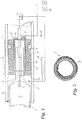
- a discharge tube 1 has at each of its ends a cap 2, of which only one is shown (the opposite is constructed in mirror image).
- the discharge tube 1 surrounds a discharge space 3, in which at each end of the tube 1, an electrode 4 is accommodated, which is supplied via a cable 5 as an electrical connection with power.
- This can lead to higher temperatures in some applications, such as UV tubes.
- the melting zone 6 lying between the electrode 4 and the cable 5 is relatively temperature-sensitive. That's why it's important for a good and rawird. This can lead to higher temperatures in some applications, such as UV tubes.
- the melting zone 6 lying between the electrode 4 and the cable 5 is relatively temperature-sensitive. Therefore, it is important to ensure a good and rapid heat transfer to the outside against the tube 1 surrounding transparent or translucent tube 8 as a cover for the tube 1.
- the cap 2 has an annular spring element 7 in the form of a helical spring, which in Fig. 1 roughly schematic, in Fig. 2 is shown more clearly.
- This spring element 7 fulfills two different tasks. On the one hand tolerances between tube and tube are compensated by its radially acting tension, on the other hand is the coil spring 7 with a relatively large area of the cap 2 and tube 8, so that a good heat transfer is given.
- the coil spring 7 is inclined to its center line A (at least in sections) on all sides, ie it is designed as, for example, in the US-A-2012/0098179 is shown. In other words, the turns of the spring 7 are skewed to its center line A. This results in a better radial force and a more flat concerns of the spring 7 on the outer tube 8.
- the coil spring 7 per centimeter of its circumference has been preferred a number of turns of at least 7, preferably about 10.
- the heat transfer surface of the coil spring 7 is further increased if - as shown - it is inserted into an annular groove 9 of a metal sleeve 10.
- the metal shell 10 may be made of copper, but is advantageously formed of an aluminum alloy.
- the metal sleeve 10 is seated on a ceramic sleeve 11 which is thin relative to it and which bears against the electrode 4 to form a flange 12.
- a heat-conducting a compensation of the heat-related elongations permitting material 13, such as graphite, in particular a graphite foil is disposed therebetween.
- Graphite meets both conditions, namely a good heat conduction, but also a kind of "lubrication", which allows for the high heat caused by some elongations between the ceramic material of the sleeve 11 and the metal sleeve 10.
- the outer circumference of the metal sleeve 10 radiates radiant heat against the tube 8, which may be cooled from the outside. This inevitably arises when the tube 1 is a UV tube for the treatment of fluids, preferably water, in particular for disinfection.
- a merely schematically indicated, per se known cooling device 16 could be provided and possibly controlled by a temperature sensor 17 arranged in the interior of the expansion. Alternatively or additionally, however, the temperature sensor 17 may also be connected to a power control stage 18 for the tube 1.
- a simplified solution provides that the temperature sensor 17 is connected to a display unit 19, for example via a threshold value switch 20, which indicates which temperature the melting zone 6 is loaded with, or whether the temperature exceeds a certain threshold value.
- a memory 21 e.g., an RFID
- the stored identification of the lamp type and / or its serial number can then be read via a connection 22 and / or its functionality can be checked.
- this memory 21 is designed as a fault memory, which receives information from the display unit 19, for example, how often and for how long a temperature considered permissible has been exceeded.
Landscapes
- Health & Medical Sciences (AREA)
- Toxicology (AREA)
- Life Sciences & Earth Sciences (AREA)
- Hydrology & Water Resources (AREA)
- Engineering & Computer Science (AREA)
- Environmental & Geological Engineering (AREA)
- Water Supply & Treatment (AREA)
- Chemical & Material Sciences (AREA)
- Organic Chemistry (AREA)
- Resistance Heating (AREA)
- Vessels And Coating Films For Discharge Lamps (AREA)
Description
- Die vorliegende Erfindung bezieht sich auf eine geschlossen aufgebaute Entladungsröhre, die an beiden Enden jeweils eine mit dem jeweiligen elektrischen Anschluss versehene Kappe aufweist, wobei die Röhre in einem transparenten oder durchscheinenden Rohr als Abdeckung untergebracht ist und zwischen Röhre und Rohr endseitig der Röhre jeweils ein in Radialrichtung federndes Federelement eingebaut ist.
- Ein derartiger Aufbau ist aus der
GB 623,999 -
US 2 009 226 A zeigt eine Entladungsröhre mit jeweils rohrförmigem Innengefäss 1 und Aussengefäss 2, bei der die beiden elektrischen Anschlüsse in einem gemeinsamen Füsschen bei einem Schraubsockel 22 angeordnet und mit Kontaktbereichen des Schraubsockels verbunden sind. Auf die beiden Endteile des Innengefässes 1 sind zwei Metallringe 11,12 mit rinnenartigen Querschnitt aufgeschoben. Zwischen den Metallringen 11, 12 und dem Aussengefäss 2 sind federnde Schraubendrahtringe 15, 16 fest eingeklemmt. Das Innengefäss wird durch diese es konzentrisch umschliessenden Schraubendrahtringe vom Aussengefäss 2 abgestützt. - Die
SU 779 727 A1 - Dadurch, dass eine Schraubenfeder mit relativ enger Windung verwendet wird, vorzugsweise mit einer Windungszahl von mindestens 7, vorzugsweise etwa 10 Windungen, pro Zentimeter Ihres Umfangs, und daher flächig an den der Aussenseite der Röhre bzw. an der Innenseite des Rohres anliegt, ergibt sich ein guter Wärmeübergang, wobei der Ausgleich von Toleranzen des Abstandes der beiden Teile (z.B. durch Unebenheiten des Rohres) durch die Elastizität der Windungen gegeben sein kann.
- Ein noch besserer Ausgleich mit der Möglichkeit der Vergrösserung der Kontaktflächen ergibt sich durch eine Ausbildung gemäss dem Anspruch 2. Derartige zu ihrer Mittelliniemindestens abschnittsweise allseitig geneigte Schraubenfedern sind aus zahlreichen Schriften bekannt, und es seien als Beispiel und zum besseren Verständnis die US-Patentdokumente
3,468,527 ;4,655,462 ;4,826,144 ;4,830,344 ;4,876,781 ;4,892,795 ;4,907,788 ;4,915,366 ;4,917,302 ;4,961,253 ;4,974,821 ;4,964,204 ;5,160,122 ;5,108, 078 ;5,139,243 ;5,139,276 ;5,203,849 ;5,239,737 ;5,503,375 ;5,542,682 ;5,615,870 ;5,709,371 ;5,791,638 ;7,055,812 ;7,274,964 und2012/0098179 genannt, wobei im Rahmen der vorliegenden Erfindung alle die dort gezeigten Federformen im Sinne des Anspruches 2 zu verstehen sind und mit Vorteil angewendet werden können, weil so auch die (bezüglich von Röhre und Rohr) radiale Elastizität verbessert wird. - Die Metallhülse kann mit Vorteile an einer relativ dünnen Keramikhülse mit der Röhre zugewandten Flansch sitzen, wobei der Wärmeübergang von dieser auf die Metallhülse über ein wärmeleitendes, einen Ausgleich der wärmebedingten Längendehnungen zulassendes Material, wie Graphit, insbesondere eine Graphitfolie, erfolgt. Diese Lösung ist auch unabhängig von der Verwendung einer Schraubenfeder einerseits für einen guten Wärmeübergang und anderseits für einen Ausgleich unterschiedlicher Wärmedehnungen günstig und stell daher an sich eine davon auch unabhängige Erfindung dar.
- Die Erfindung bezieht sich ferner auf die Verwendung eines solchen Aufbaues im Sinne des Anspruches 8.
- Weitere Einzelheiten der Erfindung ergeben sich aus der nachfolgenden Beschreibung eines bevorzugten Ausführungsbeispiels an Hand der Zeichnung. Es zeigen:
- Fig. 1
- einen Längsschnitt durch den Aufbau einer der beiden Endkappen einer UV-Röhre; und
- Fig. 2
- eine Ansicht auf eine mögliche und bevorzugte Ausführung einer im Aufbau der
Fig. 2 verwendeten Schraubenfeder. - Eine Entladungsröhre 1 weist an jedem ihrer Enden eine Kappe 2 auf, wovon nur eine dargestellt ist (die gegenüberliegende ist spiegelbildlich aufgebaut). Die Entladungsröhre 1 umgibt einen Entladungsraum 3, in dem an jedem Ende der Röhre 1 eine Elektrode 4 untergebracht ist, welche über ein Kabel 5 als elektrischer Anschluss mit Strom versorgt wird. Dabei kann es bei manchen Anwendungen, wie bei UV-Röhren, zu höheren Temperaturen kommen. Die zwischen der Elektrode 4 und dem Kabel 5 liegende Einschmelzzone 6 ist aber relativ temperaturempfindlich. Deshalb ist es wichtig, für einen guten und rawird. Dabei kann es bei manchen Anwendungen, wie bei UV-Röhren, zu höheren Temperaturen kommen. Die zwischen der Elektrode 4 und dem Kabel 5 liegende Einschmelzzone 6 ist aber relativ temperaturempfindlich. Deshalb ist es wichtig, für einen guten und raschen Wärmeübergang nach aussen gegen ein die Röhre 1 umgebendes transparentes oder durchscheinendes Rohr 8 als Abdeckung für die Röhre 1 zu sorgen.
- Die Kappe 2 besitzt ein ringförmiges Federelement 7 in Form einer Schraubenfeder, das in
Fig. 1 grob schematisch, inFig. 2 hingegen deutlicher dargestellt ist. Dieses Federelement 7 erfüllt zwei unterschiedliche Aufgaben. Einerseits werden durch seine radial wirkende Spannung Toleranzen zwischen Röhre und Rohr ausgeglichen, anderseits liegt die Schraubenfeder 7 mit einer relativ grossen Fläche an Kappe 2 und Rohr 8 an, so dass ein guter Wärmeübergang gegeben ist. WieFig. 2 zeigt, ist die Schraubenfeder 7 zu ihrer Mittellinie A (mindestens abschnittsweise) allseitig geneigt, d.h. sie ist so ausgeführt, wie dies beispielsweise in derUS-A-2012/0098179 dargestellt ist. Anders ausgedrückt, liegen die Windungen der Feder 7 schief zu ihrer Mittellinie A. Dadurch ergibt sich eine bessere Radialkraft und ein flächigeres Anliegen der Feder 7 am äusseren Rohr 8. Um eine möglichst grosse Federfläche zu sichern, hat die Schraubenfeder 7 pro Zentimeter Ihres Umfangs bevorzugt eine Windungszahl von mindestens 7, vorzugsweise etwa 10. - Die Wärmeübergangsfläche der Schraubenfeder 7 wird noch vergrössert, wenn - wie dargestellt - sie in eine Ringnut 9 einer Metallhülse 10 eingelegt ist. Die Metallhülse 10 kann aus Kupfer sein, ist aber vorteilhaft aus einer Aluminiumlegierung gebildet. Die Metallhülse 10 sitzt auf einer relativ zu ihr dünnen Keramikhülse 11, die gegen die Elektrode 4 zu einen Flansch 12 trägt. Um den Wärmeübergang von der Keramikhülse 11 zur Metallhülse 10 zu verbessern, ist dazwischen ein wärmeleitendes, einen Ausgleich der wärmebedingten Längendehnungen zulassendes Material 13, wie Graphit, insbesondere eine Graphitfolie, angeordnet. Graphit erfüllt beide Bedingungen, nämlich die einer guten Wärmeleitung, aber auch die einer Art "Schmierung", welche durch die unter Umständen hohe Wärme bedingte Längendehnungen zwischen dem Keramikmaterial der Hülse 11 und der Metallhülse 10 zulässt. Der Aussenumfang der Metallhülse 10 gibt Strahlungswärme gegen das Rohr 8 ab, das von aussen her gekühlt sein kann. Dies ergibt sich zwangsläufig dann, wenn die Röhre 1 eine UV-Röhre zur Behandlung von Fluiden ist, vorzugsweise von Wasser, insbesondere zur Desinfektion. Andernfalls könnte eine lediglich schematisch angedeutete, an sich bekannte Kühleinrichtung 16 vorgesehen und allenfalls von einem im Inneren des Ausbaues angeordneten Temperatursensor 17 gesteuert werden. Alternativ oder zusätzlich kann der Temperatursensor 17 aber auch an eine Leistungsregelstufe 18 für die Röhre 1 angeschlossen sein. Eine vereinfachte Lösung sieht vor, dass der Temperatursensor 17 an eine Anzeigeeinheit 19, z.B. über einen Schwellwertschalter 20, angeschlossen ist, durch welche angezeigt wird, mit welcher Temperatur die Einschmelzzone 6 belastet ist, bzw. ob die Temperatur einen bestimmten Schwellwert überschreitet.
- Es ist vorteilhaft, wenn die beiden Hülsen 10, 11 lösbar miteinander verbunden sind, und zu diesem Zwecke ist ein die Metallhülse 10 festhaltender Schnappring 14 in eine Vertiefung oder Nut 15 eingesetzt. Zum Lösen der Verbindung braucht also dieser Schnappring 14 nur abgezogen zu werden.
- Es ist vorteilhaft, wenn mit der Röhre 1, z.B. mit der Keramikhülse 11 ihrer Kappe 2, ein Speicher 21 (z.B. ein RFID) verbunden ist. Über einen Anschluss 22 kann dann beispielsweise die eingespeicherte Identifizierung des Lampentyps und/oder seiner Seriennummer abgelesen und/oder seine Funktionsfähigkeit überprüft werden. Auch ist es etwa möglich, dass dieser Speicher 21 als Fehlerspeicher ausgebildet ist, der beispielsweise von der Anzeigeeinheit 19 Informationen erhält, wie oft und wie lange eine als zulässig erachtete Temperatur überschritten wurde.
- Im Rahmen der Erfindung sind zahlreiche Abwandlungen möglich; beispielsweise kann an Stelle einer Schraubenfeder 7 deren zwei über die axiale Länge der Kappe 2 vorgesehen sein.
Claims (5)
- Geschlossen aufgebaute Entladungsröhre (1) die an beiden Enden jeweils eine mit dem jeweiligen elektrischen Anschluss (5) versehene Kappe (2) aufweist, wobei die Entladungsröhre (1) in einem als Abdeckung dienenden transparenten oder durchscheinenden Rohr (8) untergebracht ist und zwischen Entladungsröhre (1) und Rohr (8) endseitig der Entladungsröhre (1) jeweils ein in Radialrichtung federndes Federelement (7) eingebaut ist, wobei als Federelement eine zu einem Ring geschlossene Schraubenfeder (7) eingesetzt ist, durch welche einerseits Toleranzen zwischen Entladungsröhre (1) und Rohr (8) ausgleichbar sind und anderseits über die Schraubenflächen ein Wärmeübergang erzielbar ist, dadurch gekennzeichnet, dass die Kappen (2) der Entladungsröhre (1) je eine den jeweiligen elektrischen Anschluss (5) umgebende Metallhülse (10) aus Aluminium oder Kupfer mit einer Ringnut (9) umfassen wobei die Schraubenfeder (7) in der Ringnut (9) der Metallhülse (10) sitzt.
- Entladungsröhre (1) nach Anspruch 1, dadurch gekennzeichnet, dass als Schraubenfeder (7) eine axial federnde Schraubenfeder vorgesehen ist, deren Windungen schief zu ihrer Mittellinie (A) liegen.
- Entladungsröhre (1) nach Anspruch 1, dadurch gekennzeichnet, dass die Metallhülse (10) an einer relativ dünnen Keramikhülse (11) mit der Entladungsröhre (1) zugewandtem Flansch (12) sitzt und der Wärmeübergang von dieser auf die Metallhülse (10) über ein wärmeleitendes, einen Ausgleich der wärmebedingten Längendehnungen zulassendes Material (13), wie Graphit, insbesondere eine Graphitfolie, erfolgt.
- Entladungsröhre (1) nach Anspruch 3, dadurch gekennzeichnet, dass Keramikhülse (11) und Metallhülse (10) lösbar, z.B. über einen Schnappring (14), miteinander verbunden sind.
- Entladungsröhre (1) nach einem der vorhergehenden Ansprüche, dadurch gekennzeichnet, dass im Bereich der Entladungsröhre (1) bzw. ihrer Kappe (2) ein Temperatursensor (17) untergebracht ist, durch den eine Leistungsregelung (18) für die Entladungsröhre (1), und/oder eine Regelung einer Kühlung (16) und/oder eine Anzeigeeinheit (19) ansteuerbar ist.
Applications Claiming Priority (2)
| Application Number | Priority Date | Filing Date | Title |
|---|---|---|---|
| CH01424/12A CH706850A2 (de) | 2012-08-20 | 2012-08-20 | Entladungsröhre. |
| PCT/EP2013/066643 WO2014029632A2 (de) | 2012-08-20 | 2013-08-08 | Geschlossener aufbau für eine entladungsröhre |
Publications (2)
| Publication Number | Publication Date |
|---|---|
| EP2885809A2 EP2885809A2 (de) | 2015-06-24 |
| EP2885809B1 true EP2885809B1 (de) | 2017-07-26 |
Family
ID=48979737
Family Applications (1)
| Application Number | Title | Priority Date | Filing Date |
|---|---|---|---|
| EP13748015.8A Active EP2885809B1 (de) | 2012-08-20 | 2013-08-08 | Entladungsröhre mit Lagerung in ringförmigen Schraubenfedern |
Country Status (3)
| Country | Link |
|---|---|
| EP (1) | EP2885809B1 (de) |
| CH (1) | CH706850A2 (de) |
| WO (1) | WO2014029632A2 (de) |
Families Citing this family (1)
| Publication number | Priority date | Publication date | Assignee | Title |
|---|---|---|---|---|
| KR20230006793A (ko) * | 2019-08-01 | 2023-01-11 | 에이티쥐 유브이 테크놀로지 리미티드 | 단일 종단을 갖는 진동 방지 자외선 램프 장치 |
Family Cites Families (7)
| Publication number | Priority date | Publication date | Assignee | Title |
|---|---|---|---|---|
| FR429872A (fr) * | 1910-05-07 | 1911-10-03 | Schmidt Sche Heissdampf | Dispositif pour le surchauffage de la vapeur dans les machines à vapeur à pistons étagés |
| GB720989A (en) * | 1952-06-05 | 1954-12-29 | Gen Electric | Improvements in and relating to electric lamp shields |
| SU779727A1 (ru) * | 1978-11-29 | 1980-11-15 | Производственное Объединение "Ватра" Им. 60-Летия Советской Украины | Устройство дл отвода тепла от криволинейной поверхности источника света |
| US4841422A (en) * | 1986-10-23 | 1989-06-20 | Lighting Technology, Inc. | Heat-dissipating light fixture for use with tungsten-halogen lamps |
| US4826144A (en) * | 1988-04-25 | 1989-05-02 | Peter J. Balsells | Inside back angle canted coil spring |
| JP2506053B2 (ja) * | 1993-11-30 | 1996-06-12 | ニューカンパニー株式会社 | 高光度放電灯照明器具 |
| EP1890330A4 (de) * | 2005-03-30 | 2010-01-20 | Jisouken Co Ltd | Kühlkörper und verfahren zu seiner herstellung |
-
2012
- 2012-08-20 CH CH01424/12A patent/CH706850A2/de not_active Application Discontinuation
-
2013
- 2013-08-08 EP EP13748015.8A patent/EP2885809B1/de active Active
- 2013-08-08 WO PCT/EP2013/066643 patent/WO2014029632A2/de not_active Ceased
Non-Patent Citations (1)
| Title |
|---|
| None * |
Also Published As
| Publication number | Publication date |
|---|---|
| WO2014029632A2 (de) | 2014-02-27 |
| WO2014029632A3 (de) | 2014-06-12 |
| EP2885809A2 (de) | 2015-06-24 |
| CH706850A2 (de) | 2014-02-28 |
Similar Documents
| Publication | Publication Date | Title |
|---|---|---|
| DE10029437B4 (de) | Infrarotstrahler und Verfahren zum Betreiben eines solchen Infrarotstrahlers | |
| DE602004010710T2 (de) | Fluoreszenzlampe für kalte umgebungen | |
| EP1262772B1 (de) | Temperaturgesteuerter Injektor für ein chemisches Analysegerät | |
| EP2486357B1 (de) | Kühleinrichtung für einen bei erhöhter umgebungstemperatur einsetzbaren sensor | |
| EP1466347A2 (de) | Amalgamdotierte quecksilberniederdruckstrahlereinheit | |
| DE2014543C3 (de) | Kollektorelektrodenanordnung für eine Laufzeitröhre | |
| EP2885809B1 (de) | Entladungsröhre mit Lagerung in ringförmigen Schraubenfedern | |
| WO2021008832A1 (de) | Elektrische stromdurchführung | |
| DE112015006539T5 (de) | Metallschmelze-warmhalteofen | |
| EP3424266B1 (de) | Heizpatrone mit einem schutzrohr | |
| EP1913322B1 (de) | Abstichkanal für einen metallurgischen ofen | |
| DE102005036768A1 (de) | Heizgerät mit thermoelektrischer Einrichtung | |
| DE102014105769B4 (de) | Infrarotstrahler mit gleitgelagertem Heizfilament | |
| DE102018105888B4 (de) | Schweißbrenner | |
| EP2840328A1 (de) | Heizgerät mit thermoelektrischem Modul | |
| DE10315795B4 (de) | Leuchte | |
| EP2182284A1 (de) | Elektrodeanordnung | |
| DE4211163A1 (de) | Hochleistungsscheinwerfer | |
| DE102024109844A1 (de) | Verbindungshülse, Kabelverschraubung und Verwendung | |
| EP2276962A1 (de) | Keramikkompensator für radiale und axiale beweglichkeit mit wasserschutz | |
| EP3279920B1 (de) | Zentrierelement und halterung für elektrische leuchtmittel | |
| DE837577C (de) | Elektronenroehre, insbesondere fuer hohe Leistungen | |
| DE202009004939U1 (de) | Elektrische Ausglühvorrichtung, insbesondere für Impfösen | |
| AT24172B (de) | Thermoelektrischer Ofen. | |
| DE3839970A1 (de) | Ofen mit einem dynamischen temperaturgradienten |
Legal Events
| Date | Code | Title | Description |
|---|---|---|---|
| PUAI | Public reference made under article 153(3) epc to a published international application that has entered the european phase |
Free format text: ORIGINAL CODE: 0009012 |
|
| 17P | Request for examination filed |
Effective date: 20150129 |
|
| AK | Designated contracting states |
Kind code of ref document: A2 Designated state(s): AL AT BE BG CH CY CZ DE DK EE ES FI FR GB GR HR HU IE IS IT LI LT LU LV MC MK MT NL NO PL PT RO RS SE SI SK SM TR |
|
| AX | Request for extension of the european patent |
Extension state: BA ME |
|
| DAX | Request for extension of the european patent (deleted) | ||
| GRAP | Despatch of communication of intention to grant a patent |
Free format text: ORIGINAL CODE: EPIDOSNIGR1 |
|
| INTG | Intention to grant announced |
Effective date: 20161109 |
|
| GRAJ | Information related to disapproval of communication of intention to grant by the applicant or resumption of examination proceedings by the epo deleted |
Free format text: ORIGINAL CODE: EPIDOSDIGR1 |
|
| INTC | Intention to grant announced (deleted) | ||
| GRAP | Despatch of communication of intention to grant a patent |
Free format text: ORIGINAL CODE: EPIDOSNIGR1 |
|
| INTG | Intention to grant announced |
Effective date: 20170322 |
|
| GRAS | Grant fee paid |
Free format text: ORIGINAL CODE: EPIDOSNIGR3 |
|
| GRAA | (expected) grant |
Free format text: ORIGINAL CODE: 0009210 |
|
| AK | Designated contracting states |
Kind code of ref document: B1 Designated state(s): AL AT BE BG CH CY CZ DE DK EE ES FI FR GB GR HR HU IE IS IT LI LT LU LV MC MK MT NL NO PL PT RO RS SE SI SK SM TR |
|
| REG | Reference to a national code |
Ref country code: GB Ref legal event code: FG4D Free format text: NOT ENGLISH |
|
| REG | Reference to a national code |
Ref country code: CH Ref legal event code: EP |
|
| REG | Reference to a national code |
Ref country code: AT Ref legal event code: REF Ref document number: 913027 Country of ref document: AT Kind code of ref document: T Effective date: 20170815 |
|
| REG | Reference to a national code |
Ref country code: IE Ref legal event code: FG4D Free format text: LANGUAGE OF EP DOCUMENT: GERMAN |
|
| REG | Reference to a national code |
Ref country code: DE Ref legal event code: R096 Ref document number: 502013007866 Country of ref document: DE |
|
| REG | Reference to a national code |
Ref country code: NL Ref legal event code: FP |
|
| REG | Reference to a national code |
Ref country code: LT Ref legal event code: MG4D |
|
| REG | Reference to a national code |
Ref country code: NO Ref legal event code: T2 Effective date: 20170726 |
|
| PG25 | Lapsed in a contracting state [announced via postgrant information from national office to epo] |
Ref country code: HR Free format text: LAPSE BECAUSE OF FAILURE TO SUBMIT A TRANSLATION OF THE DESCRIPTION OR TO PAY THE FEE WITHIN THE PRESCRIBED TIME-LIMIT Effective date: 20170726 Ref country code: LT Free format text: LAPSE BECAUSE OF FAILURE TO SUBMIT A TRANSLATION OF THE DESCRIPTION OR TO PAY THE FEE WITHIN THE PRESCRIBED TIME-LIMIT Effective date: 20170726 Ref country code: FI Free format text: LAPSE BECAUSE OF FAILURE TO SUBMIT A TRANSLATION OF THE DESCRIPTION OR TO PAY THE FEE WITHIN THE PRESCRIBED TIME-LIMIT Effective date: 20170726 Ref country code: SE Free format text: LAPSE BECAUSE OF FAILURE TO SUBMIT A TRANSLATION OF THE DESCRIPTION OR TO PAY THE FEE WITHIN THE PRESCRIBED TIME-LIMIT Effective date: 20170726 |
|
| PG25 | Lapsed in a contracting state [announced via postgrant information from national office to epo] |
Ref country code: LV Free format text: LAPSE BECAUSE OF FAILURE TO SUBMIT A TRANSLATION OF THE DESCRIPTION OR TO PAY THE FEE WITHIN THE PRESCRIBED TIME-LIMIT Effective date: 20170726 Ref country code: ES Free format text: LAPSE BECAUSE OF FAILURE TO SUBMIT A TRANSLATION OF THE DESCRIPTION OR TO PAY THE FEE WITHIN THE PRESCRIBED TIME-LIMIT Effective date: 20170726 Ref country code: GR Free format text: LAPSE BECAUSE OF FAILURE TO SUBMIT A TRANSLATION OF THE DESCRIPTION OR TO PAY THE FEE WITHIN THE PRESCRIBED TIME-LIMIT Effective date: 20171027 Ref country code: BG Free format text: LAPSE BECAUSE OF FAILURE TO SUBMIT A TRANSLATION OF THE DESCRIPTION OR TO PAY THE FEE WITHIN THE PRESCRIBED TIME-LIMIT Effective date: 20171026 Ref country code: PL Free format text: LAPSE BECAUSE OF FAILURE TO SUBMIT A TRANSLATION OF THE DESCRIPTION OR TO PAY THE FEE WITHIN THE PRESCRIBED TIME-LIMIT Effective date: 20170726 Ref country code: RS Free format text: LAPSE BECAUSE OF FAILURE TO SUBMIT A TRANSLATION OF THE DESCRIPTION OR TO PAY THE FEE WITHIN THE PRESCRIBED TIME-LIMIT Effective date: 20170726 Ref country code: IS Free format text: LAPSE BECAUSE OF FAILURE TO SUBMIT A TRANSLATION OF THE DESCRIPTION OR TO PAY THE FEE WITHIN THE PRESCRIBED TIME-LIMIT Effective date: 20171126 |
|
| REG | Reference to a national code |
Ref country code: CH Ref legal event code: PL |
|
| PG25 | Lapsed in a contracting state [announced via postgrant information from national office to epo] |
Ref country code: RO Free format text: LAPSE BECAUSE OF FAILURE TO SUBMIT A TRANSLATION OF THE DESCRIPTION OR TO PAY THE FEE WITHIN THE PRESCRIBED TIME-LIMIT Effective date: 20170726 Ref country code: LI Free format text: LAPSE BECAUSE OF NON-PAYMENT OF DUE FEES Effective date: 20170831 Ref country code: CZ Free format text: LAPSE BECAUSE OF FAILURE TO SUBMIT A TRANSLATION OF THE DESCRIPTION OR TO PAY THE FEE WITHIN THE PRESCRIBED TIME-LIMIT Effective date: 20170726 Ref country code: DK Free format text: LAPSE BECAUSE OF FAILURE TO SUBMIT A TRANSLATION OF THE DESCRIPTION OR TO PAY THE FEE WITHIN THE PRESCRIBED TIME-LIMIT Effective date: 20170726 Ref country code: CH Free format text: LAPSE BECAUSE OF NON-PAYMENT OF DUE FEES Effective date: 20170831 Ref country code: MC Free format text: LAPSE BECAUSE OF FAILURE TO SUBMIT A TRANSLATION OF THE DESCRIPTION OR TO PAY THE FEE WITHIN THE PRESCRIBED TIME-LIMIT Effective date: 20170726 |
|
| REG | Reference to a national code |
Ref country code: DE Ref legal event code: R097 Ref document number: 502013007866 Country of ref document: DE |
|
| REG | Reference to a national code |
Ref country code: IE Ref legal event code: MM4A |
|
| PG25 | Lapsed in a contracting state [announced via postgrant information from national office to epo] |
Ref country code: SK Free format text: LAPSE BECAUSE OF FAILURE TO SUBMIT A TRANSLATION OF THE DESCRIPTION OR TO PAY THE FEE WITHIN THE PRESCRIBED TIME-LIMIT Effective date: 20170726 Ref country code: EE Free format text: LAPSE BECAUSE OF FAILURE TO SUBMIT A TRANSLATION OF THE DESCRIPTION OR TO PAY THE FEE WITHIN THE PRESCRIBED TIME-LIMIT Effective date: 20170726 Ref country code: SM Free format text: LAPSE BECAUSE OF FAILURE TO SUBMIT A TRANSLATION OF THE DESCRIPTION OR TO PAY THE FEE WITHIN THE PRESCRIBED TIME-LIMIT Effective date: 20170726 Ref country code: IT Free format text: LAPSE BECAUSE OF FAILURE TO SUBMIT A TRANSLATION OF THE DESCRIPTION OR TO PAY THE FEE WITHIN THE PRESCRIBED TIME-LIMIT Effective date: 20170726 |
|
| PLBE | No opposition filed within time limit |
Free format text: ORIGINAL CODE: 0009261 |
|
| STAA | Information on the status of an ep patent application or granted ep patent |
Free format text: STATUS: NO OPPOSITION FILED WITHIN TIME LIMIT |
|
| REG | Reference to a national code |
Ref country code: BE Ref legal event code: MM Effective date: 20170831 |
|
| PG25 | Lapsed in a contracting state [announced via postgrant information from national office to epo] |
Ref country code: LU Free format text: LAPSE BECAUSE OF NON-PAYMENT OF DUE FEES Effective date: 20170808 |
|
| 26N | No opposition filed |
Effective date: 20180430 |
|
| REG | Reference to a national code |
Ref country code: FR Ref legal event code: ST Effective date: 20180607 |
|
| PG25 | Lapsed in a contracting state [announced via postgrant information from national office to epo] |
Ref country code: IE Free format text: LAPSE BECAUSE OF NON-PAYMENT OF DUE FEES Effective date: 20170808 |
|
| PG25 | Lapsed in a contracting state [announced via postgrant information from national office to epo] |
Ref country code: SI Free format text: LAPSE BECAUSE OF FAILURE TO SUBMIT A TRANSLATION OF THE DESCRIPTION OR TO PAY THE FEE WITHIN THE PRESCRIBED TIME-LIMIT Effective date: 20170726 Ref country code: BE Free format text: LAPSE BECAUSE OF NON-PAYMENT OF DUE FEES Effective date: 20170831 Ref country code: FR Free format text: LAPSE BECAUSE OF NON-PAYMENT OF DUE FEES Effective date: 20170926 |
|
| PG25 | Lapsed in a contracting state [announced via postgrant information from national office to epo] |
Ref country code: MT Free format text: LAPSE BECAUSE OF FAILURE TO SUBMIT A TRANSLATION OF THE DESCRIPTION OR TO PAY THE FEE WITHIN THE PRESCRIBED TIME-LIMIT Effective date: 20170726 |
|
| PG25 | Lapsed in a contracting state [announced via postgrant information from national office to epo] |
Ref country code: HU Free format text: LAPSE BECAUSE OF FAILURE TO SUBMIT A TRANSLATION OF THE DESCRIPTION OR TO PAY THE FEE WITHIN THE PRESCRIBED TIME-LIMIT; INVALID AB INITIO Effective date: 20130808 |
|
| REG | Reference to a national code |
Ref country code: AT Ref legal event code: MM01 Ref document number: 913027 Country of ref document: AT Kind code of ref document: T Effective date: 20180808 |
|
| PG25 | Lapsed in a contracting state [announced via postgrant information from national office to epo] |
Ref country code: CY Free format text: LAPSE BECAUSE OF FAILURE TO SUBMIT A TRANSLATION OF THE DESCRIPTION OR TO PAY THE FEE WITHIN THE PRESCRIBED TIME-LIMIT Effective date: 20170726 |
|
| PG25 | Lapsed in a contracting state [announced via postgrant information from national office to epo] |
Ref country code: MK Free format text: LAPSE BECAUSE OF FAILURE TO SUBMIT A TRANSLATION OF THE DESCRIPTION OR TO PAY THE FEE WITHIN THE PRESCRIBED TIME-LIMIT Effective date: 20170726 |
|
| PG25 | Lapsed in a contracting state [announced via postgrant information from national office to epo] |
Ref country code: AT Free format text: LAPSE BECAUSE OF NON-PAYMENT OF DUE FEES Effective date: 20180808 |
|
| PG25 | Lapsed in a contracting state [announced via postgrant information from national office to epo] |
Ref country code: TR Free format text: LAPSE BECAUSE OF FAILURE TO SUBMIT A TRANSLATION OF THE DESCRIPTION OR TO PAY THE FEE WITHIN THE PRESCRIBED TIME-LIMIT Effective date: 20170726 |
|
| PG25 | Lapsed in a contracting state [announced via postgrant information from national office to epo] |
Ref country code: PT Free format text: LAPSE BECAUSE OF FAILURE TO SUBMIT A TRANSLATION OF THE DESCRIPTION OR TO PAY THE FEE WITHIN THE PRESCRIBED TIME-LIMIT Effective date: 20170726 |
|
| PG25 | Lapsed in a contracting state [announced via postgrant information from national office to epo] |
Ref country code: AL Free format text: LAPSE BECAUSE OF FAILURE TO SUBMIT A TRANSLATION OF THE DESCRIPTION OR TO PAY THE FEE WITHIN THE PRESCRIBED TIME-LIMIT Effective date: 20170726 |
|
| PGFP | Annual fee paid to national office [announced via postgrant information from national office to epo] |
Ref country code: NL Payment date: 20250826 Year of fee payment: 13 |
|
| PGFP | Annual fee paid to national office [announced via postgrant information from national office to epo] |
Ref country code: DE Payment date: 20250828 Year of fee payment: 13 |
|
| PGFP | Annual fee paid to national office [announced via postgrant information from national office to epo] |
Ref country code: NO Payment date: 20250829 Year of fee payment: 13 |
|
| PGFP | Annual fee paid to national office [announced via postgrant information from national office to epo] |
Ref country code: GB Payment date: 20250827 Year of fee payment: 13 |