EP2886408A1 - Elektronische Steuerungseinheit und Hydraulikdrucksteuerungseinheit für Fahrzeugbremse - Google Patents
Elektronische Steuerungseinheit und Hydraulikdrucksteuerungseinheit für Fahrzeugbremse Download PDFInfo
- Publication number
- EP2886408A1 EP2886408A1 EP14193424.0A EP14193424A EP2886408A1 EP 2886408 A1 EP2886408 A1 EP 2886408A1 EP 14193424 A EP14193424 A EP 14193424A EP 2886408 A1 EP2886408 A1 EP 2886408A1
- Authority
- EP
- European Patent Office
- Prior art keywords
- attaching
- base body
- control unit
- flange
- housing
- Prior art date
- Legal status (The legal status is an assumption and is not a legal conclusion. Google has not performed a legal analysis and makes no representation as to the accuracy of the status listed.)
- Granted
Links
Images



Classifications
-
- B—PERFORMING OPERATIONS; TRANSPORTING
- B60—VEHICLES IN GENERAL
- B60T—VEHICLE BRAKE CONTROL SYSTEMS OR PARTS THEREOF; BRAKE CONTROL SYSTEMS OR PARTS THEREOF, IN GENERAL; ARRANGEMENT OF BRAKING ELEMENTS ON VEHICLES IN GENERAL; PORTABLE DEVICES FOR PREVENTING UNWANTED MOVEMENT OF VEHICLES; VEHICLE MODIFICATIONS TO FACILITATE COOLING OF BRAKES
- B60T8/00—Arrangements for adjusting wheel-braking force to meet varying vehicular or ground-surface conditions, e.g. limiting or varying distribution of braking force
- B60T8/17—Using electrical or electronic regulation means to control braking
-
- B—PERFORMING OPERATIONS; TRANSPORTING
- B60—VEHICLES IN GENERAL
- B60T—VEHICLE BRAKE CONTROL SYSTEMS OR PARTS THEREOF; BRAKE CONTROL SYSTEMS OR PARTS THEREOF, IN GENERAL; ARRANGEMENT OF BRAKING ELEMENTS ON VEHICLES IN GENERAL; PORTABLE DEVICES FOR PREVENTING UNWANTED MOVEMENT OF VEHICLES; VEHICLE MODIFICATIONS TO FACILITATE COOLING OF BRAKES
- B60T8/00—Arrangements for adjusting wheel-braking force to meet varying vehicular or ground-surface conditions, e.g. limiting or varying distribution of braking force
- B60T8/32—Arrangements for adjusting wheel-braking force to meet varying vehicular or ground-surface conditions, e.g. limiting or varying distribution of braking force responsive to a speed condition, e.g. acceleration or deceleration
- B60T8/34—Arrangements for adjusting wheel-braking force to meet varying vehicular or ground-surface conditions, e.g. limiting or varying distribution of braking force responsive to a speed condition, e.g. acceleration or deceleration having a fluid pressure regulator responsive to a speed condition
- B60T8/36—Arrangements for adjusting wheel-braking force to meet varying vehicular or ground-surface conditions, e.g. limiting or varying distribution of braking force responsive to a speed condition, e.g. acceleration or deceleration having a fluid pressure regulator responsive to a speed condition including a pilot valve responding to an electromagnetic force
- B60T8/3615—Electromagnetic valves specially adapted for anti-lock brake and traction control systems
- B60T8/3675—Electromagnetic valves specially adapted for anti-lock brake and traction control systems integrated in modulator units
- B60T8/368—Electromagnetic valves specially adapted for anti-lock brake and traction control systems integrated in modulator units combined with other mechanical components, e.g. pump units, master cylinders
-
- B—PERFORMING OPERATIONS; TRANSPORTING
- B60—VEHICLES IN GENERAL
- B60R—VEHICLES, VEHICLE FITTINGS, OR VEHICLE PARTS, NOT OTHERWISE PROVIDED FOR
- B60R16/00—Electric or fluid circuits specially adapted for vehicles and not otherwise provided for; Arrangement of elements of electric or fluid circuits specially adapted for vehicles and not otherwise provided for
- B60R16/02—Electric or fluid circuits specially adapted for vehicles and not otherwise provided for; Arrangement of elements of electric or fluid circuits specially adapted for vehicles and not otherwise provided for electric constitutive elements
- B60R16/023—Electric or fluid circuits specially adapted for vehicles and not otherwise provided for; Arrangement of elements of electric or fluid circuits specially adapted for vehicles and not otherwise provided for electric constitutive elements for transmission of signals between vehicle parts or subsystems
- B60R16/0239—Electronic boxes
-
- B—PERFORMING OPERATIONS; TRANSPORTING
- B60—VEHICLES IN GENERAL
- B60T—VEHICLE BRAKE CONTROL SYSTEMS OR PARTS THEREOF; BRAKE CONTROL SYSTEMS OR PARTS THEREOF, IN GENERAL; ARRANGEMENT OF BRAKING ELEMENTS ON VEHICLES IN GENERAL; PORTABLE DEVICES FOR PREVENTING UNWANTED MOVEMENT OF VEHICLES; VEHICLE MODIFICATIONS TO FACILITATE COOLING OF BRAKES
- B60T8/00—Arrangements for adjusting wheel-braking force to meet varying vehicular or ground-surface conditions, e.g. limiting or varying distribution of braking force
- B60T8/32—Arrangements for adjusting wheel-braking force to meet varying vehicular or ground-surface conditions, e.g. limiting or varying distribution of braking force responsive to a speed condition, e.g. acceleration or deceleration
- B60T8/34—Arrangements for adjusting wheel-braking force to meet varying vehicular or ground-surface conditions, e.g. limiting or varying distribution of braking force responsive to a speed condition, e.g. acceleration or deceleration having a fluid pressure regulator responsive to a speed condition
- B60T8/36—Arrangements for adjusting wheel-braking force to meet varying vehicular or ground-surface conditions, e.g. limiting or varying distribution of braking force responsive to a speed condition, e.g. acceleration or deceleration having a fluid pressure regulator responsive to a speed condition including a pilot valve responding to an electromagnetic force
- B60T8/3615—Electromagnetic valves specially adapted for anti-lock brake and traction control systems
- B60T8/3675—Electromagnetic valves specially adapted for anti-lock brake and traction control systems integrated in modulator units
-
- B—PERFORMING OPERATIONS; TRANSPORTING
- B60—VEHICLES IN GENERAL
- B60T—VEHICLE BRAKE CONTROL SYSTEMS OR PARTS THEREOF; BRAKE CONTROL SYSTEMS OR PARTS THEREOF, IN GENERAL; ARRANGEMENT OF BRAKING ELEMENTS ON VEHICLES IN GENERAL; PORTABLE DEVICES FOR PREVENTING UNWANTED MOVEMENT OF VEHICLES; VEHICLE MODIFICATIONS TO FACILITATE COOLING OF BRAKES
- B60T13/00—Transmitting braking action from initiating means to ultimate brake actuator with power assistance or drive; Brake systems incorporating such transmitting means, e.g. air-pressure brake systems
- B60T13/10—Transmitting braking action from initiating means to ultimate brake actuator with power assistance or drive; Brake systems incorporating such transmitting means, e.g. air-pressure brake systems with fluid assistance, drive, or release
- B60T13/66—Electrical control in fluid-pressure brake systems
-
- B—PERFORMING OPERATIONS; TRANSPORTING
- B60—VEHICLES IN GENERAL
- B60T—VEHICLE BRAKE CONTROL SYSTEMS OR PARTS THEREOF; BRAKE CONTROL SYSTEMS OR PARTS THEREOF, IN GENERAL; ARRANGEMENT OF BRAKING ELEMENTS ON VEHICLES IN GENERAL; PORTABLE DEVICES FOR PREVENTING UNWANTED MOVEMENT OF VEHICLES; VEHICLE MODIFICATIONS TO FACILITATE COOLING OF BRAKES
- B60T8/00—Arrangements for adjusting wheel-braking force to meet varying vehicular or ground-surface conditions, e.g. limiting or varying distribution of braking force
- B60T8/32—Arrangements for adjusting wheel-braking force to meet varying vehicular or ground-surface conditions, e.g. limiting or varying distribution of braking force responsive to a speed condition, e.g. acceleration or deceleration
- B60T8/34—Arrangements for adjusting wheel-braking force to meet varying vehicular or ground-surface conditions, e.g. limiting or varying distribution of braking force responsive to a speed condition, e.g. acceleration or deceleration having a fluid pressure regulator responsive to a speed condition
- B60T8/36—Arrangements for adjusting wheel-braking force to meet varying vehicular or ground-surface conditions, e.g. limiting or varying distribution of braking force responsive to a speed condition, e.g. acceleration or deceleration having a fluid pressure regulator responsive to a speed condition including a pilot valve responding to an electromagnetic force
- B60T8/3615—Electromagnetic valves specially adapted for anti-lock brake and traction control systems
- B60T8/3675—Electromagnetic valves specially adapted for anti-lock brake and traction control systems integrated in modulator units
- B60T8/368—Electromagnetic valves specially adapted for anti-lock brake and traction control systems integrated in modulator units combined with other mechanical components, e.g. pump units, master cylinders
- B60T8/3685—Electromagnetic valves specially adapted for anti-lock brake and traction control systems integrated in modulator units combined with other mechanical components, e.g. pump units, master cylinders characterised by the mounting of the modulator unit onto the vehicle
-
- Y—GENERAL TAGGING OF NEW TECHNOLOGICAL DEVELOPMENTS; GENERAL TAGGING OF CROSS-SECTIONAL TECHNOLOGIES SPANNING OVER SEVERAL SECTIONS OF THE IPC; TECHNICAL SUBJECTS COVERED BY FORMER USPC CROSS-REFERENCE ART COLLECTIONS [XRACs] AND DIGESTS
- Y10—TECHNICAL SUBJECTS COVERED BY FORMER USPC
- Y10T—TECHNICAL SUBJECTS COVERED BY FORMER US CLASSIFICATION
- Y10T137/00—Fluid handling
- Y10T137/8593—Systems
- Y10T137/877—With flow control means for branched passages
- Y10T137/87885—Sectional block structure
Definitions
- An embodiment described herein generally relates to an electronic control unit and a vehicle brake hydraulic pressure control unit.
- a vehicle brake hydraulic pressure control unit that controls a brake hydraulic pressure for a wheel brake includes a base body in which brake fluid lines are formed, a control circuit board that controls electric parts and a housing having an accommodating portion which accommodates the control circuit board thereinside.
- a vehicle brake hydraulic pressure control unit may be configured such that a base body has screw holes, a flange of a housing has attaching holes penetrating therethrough, and screw members are inserted into the attaching holes and screwed into the screw holes to thereby fix the housing to the base body (for example, refer to JP-2005-294480-A ).
- a vehicle brake hydraulic pressure control unit may be configured such that a base body has screw holes, and a bottom portion of a housing has attaching holes penetrating therethrough, and screw members are inserted into the attaching holes from an inside of the housing and screwed into the screw holes, to thereby fix the housing to the base body (for example, refer to JP-2004-039948-A ).
- a vehicle brake hydraulic pressure control unit may be configured such that a housing has screw holes, a base body has attaching holes penetrating therethrough, and screw members are inserted into the attaching holes and screwed into the screw holes, to thereby fix the housing to the base body (for example, refer to JP-2009-006855-A ).
- the area of the control circuit board to be used in the vehicle brake hydraulic pressure control units tends to increase, as the brakes are controlled in multiple ways.
- the size of the control circuit board may be limited.
- the housing In the configuration in which the attaching holes are formed in the bottom portion of the housing, the housing needs to be attached to the base body before the control circuit board is attached inside the housing. When the housing is removed from the base body, the control circuit board needs to be removed first. Consequently, the fabrication and maintenance of the vehicle brake hydraulic pressure control unit may become complicated and troublesome.
- the space for the attaching holes needs to be ensured in the interior of the base body so as to prevent the interference of the attaching holes with the brake fluid lines, and therefore, the base body may become large in size.
- One object of the present invention is to provide an electronic control unit and a vehicle brake hydraulic pressure control unit that can not only increase the capacity of an accommodating portion for accommodating a control circuit board but also facilitate the fabrication and maintenance thereof.
- An aspect of the present invention provides an electronic control unit including: a base body; a control circuit board that controls electric parts; and a housing that is attached to one surface of the base body, wherein the housing includes an accommodating portion which accommodates the control circuit board thereinside and a flange, wherein the flange includes an attaching hole penetrating therethrough, wherein a part of the accommodating portion is positioned on an extension of a center axis of the attaching hole, wherein an attaching pin projects from the one surface of the base body so as to be inserted into the attaching hole, wherein an attaching portion is formed on the attaching pin so as to be positioned between the flange and the accommodating portion, and wherein an elastic member is attached to the attaching portion so as to bias the flange toward the one surface of the base body.
- the accommodating portion of the housing can be caused to project also in a position where the accommodating portion covers the attaching hole in the flange, the capacity of the accommodating portion can be increased.
- the housing can be attached to or detached from the base body with the control circuit board attached within the housing, the fabrication and maintenance of the electronic control unit can be facilitated.
- the base body can be reduced in size.
- a brake fluid line is formed in the base body, and a brake hydraulic pressure within the brake fluid line is controlled by the electric parts.
- the control circuit board can be accommodated in the housing.
- the housing can be attached to the base body without affecting the brake fluid line in the base body.
- the elastic member in the case of the elastic member being a bifurcating plate spring that holds the attaching portion of the attaching pin, the elastic member can be inserted between the flange and the accommodating portion from a side of the base body to attach the elastic member to the attaching pin.
- the space between the flange and the accommodating portion can be reduced, thereby reducing the housing in size in a height direction.
- the base body can be reduced in size while increasing the space for accommodating the control circuit board. Additionally, the fabrication and maintenance of the electronic control unit and the vehicle brake hydraulic pressure control unit can be facilitated.
- a vehicle brake hydraulic pressure control unit is used in a four-wheeled motor vehicle.
- the vehicle brake hydraulic pressure control unit controls brake hydraulic pressures to be imparted to wheel cylinders of wheel brakes, enabling the execution of such controls as anti-lock braking control, vehicle behavior stabilization control and the like.
- the vehicle brake hydraulic pressure control unit can also be installed in a hybrid vehicle employing a motor in parallel as a power source, and an electric vehicle and a fuel cell vehicle and the like employing only a motor as a power source, in addition to a motor vehicle employing only an engine (an internal combustion engine) as a power source.
- a vehicle brake hydraulic pressure control unit 1 includes a base body 10, a control circuit board 20 that controls electric parts (not shown), and a housing 30 that is attached to a front surface 10a of the base body 10.
- the base body 10 is a metallic part that is formed substantially into a rectangular parallelepiped.
- Brake fluid lines 2 are formed in an interior of the base body 10.
- the brake fluid lines 2 are fluid lines for connecting a master cylinder (not shown) and wheel brakes (not shown).
- Plural electric parts including solenoid valves, pressure sensors and the like are mounted on the front surface 10a.
- inlet ports 3, 3 are formed in upper left and right corners on a rear surface 10b of the base body 10. Pipings that reach the master cylinder (not shown) are connected to both the inlet ports 3, 3.
- Plural outlet ports 4 are formed in an upper surface 10c of the base body 10. Pipings that reach the wheel brakes (not shown) are connected to the outlet ports 4.
- a pump bore 5 is formed in a side surface 10d of the base body 10.
- a plunger pump is installed in the pump bore 5.
- a damper bore 6 is formed above the pump bore 5 in the side surface 10d of the base body 10. A part that makes up a damper for absorbing pulsations of the plunger pump is installed in the damper bore 6.
- the holes and bores that are provided in the base body 10 communicate with one another via the brake fluid lines 2.
- a motor 50 is fixed to the rear surface 10b of the base body 10.
- the motor 50 constitutes a drive source for the plunger pump.
- the housing 30 is fixed to the front surface 10a in such a state that the housing 30 covers the electric parts (not shown) that project from the front surface 10a of the base body 10.
- the housing 30 of this embodiment is a box member that is formed from a synthetic resin.
- the housing 30 includes a circumferential wall portion 31 that surrounds the electric parts, an accommodating portion 32 that accommodates the control circuit board 20, and a flange 33 that is formed on a circumferential surface of the circumferential wall portion 31.
- An open end portion of a rear side (a side facing the base body 10) of the circumferential wall portion 31 is a portion that is butted up against the front surface 10a of the base body 10.
- the flange 33 projects along the full circumference of the outer circumferential surface of the circumferential wall portion 31.
- a rear surface of the flange 33 is a portion that is butted up against an outer circumferential portion of the front surface 10a of the base body 10.
- the flange 33 has a substantially square external shape and is formed so as to be substantially the same as an external shape of the front surface 10a of the base body 10.
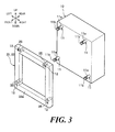
- attaching holes 35 are formed in four corners of the flange 33.
- Fig. 3 shows only part (only the flange 33) of the housing 30.
- the attaching holes 35 penetrate the flange 33 and open to a rear surface and a front surface 33a of the flange 33.
- the attaching holes 35 are portions into which attaching pins 11 of the base body 10, which will be described later, are inserted.
- the accommodating portion 32 is formed on a front side (a side opposite to the side facing the base body 10) of the circumferential wall portion 31 and projects further vertically and horizontally than the circumferential wall portion 31. When seen from the front, the accommodating portion 32 is formed into a horizontally extended rectangle.
- An interior space of the accommodating portion 32 is a space where the control circuit board 20 is accommodated.
- a front side of the accommodating portions 32 is opened, and the resulting opening portion is closed by a plate-shaped cover 40.
- the accommodating portion 32 projects largely to the right relative to the circumferential wall portion 31, and a connector connecting portion 34 is formed on a rear surface of the projecting portion.
- the connector connecting portion 34 is a portion to which a connector provided at an end portion of an external wiring cable (not shown) is connected.
- an outer circumferential portion of the accommodating portion 32 projects into a space defined in front of vertical and horizontal four corners of the flange 33.
- the outer circumferential portion of the accommodating portion 32 projects to the same position as or outward of an outer circumferential edge portion of the flange 33.
- the front surface 33a of the flange 33 and the outer circumferential portion of the accommodating portion 32 are disposed so as to be spaced apart from each other in a front-to-rear direction (a height direction of the housing 30) (refer to Fig. 2 ). Namely, recess portions 36 are formed in corner portions of the housing 30 in such a manner as to be held by the flange 33 and the outer circumferential portion of the accommodating portion 32.
- the outer circumferential portion of the accommodating portion 32 is positioned on extensions of center axes of the attaching holes 35 in the flange 33, and front opening portions of the attaching holes 35 are covered by the outer circumferential portion of the accommodating portion 32.
- the attaching pins 11 provided on the front surface 10a of the base body 10 so as to project therefrom are inserted into the attaching holes 35 in the flange 33 of the housing 30.
- the housing 30 is fixed to the front surface 10a of the base body 10 by attaching elastic clips 60 (an “elastic member” in claims) to distal end portions of the attaching pins 11 that project to the front side of the flange 33.
- the attaching pins 11 are provided at four corners of the front surface 10a of the base body 10 so as to project therefrom. Proximal end portions of the attaching pins 11 are inserted in bottomed holes 13 (refer to Fig. 2 ) that are formed in the four corners of the front surface 10a of the base body 10.
- the attaching holes 35 in the flange 33 of the housing 30 are formed in the positions that correspond to the attaching pins 11 of the base body 10. Consequently, when the flange 33 is butted up against the front surface 10a of the base body 10, the flange 33 is disposed on the front surface 10a so that the attaching pins 11 are inserted into the corresponding attaching holes 35.
- a length of a portion that projects from the front surface 10a of the base body 10 is larger than a thickness of the flange 33. Consequently, as shown in Fig. 2 , when the flange 33 is butted up against the front surface 10a of the base body 10, the attaching pins 11 penetrate the attaching holes 35 so that the distal end portions of the attaching pins 11 project to the front side of the flange 33. This allows the distal end portions of the attaching pins 11 to be disposed within the recess portions 36 defined between the front surface 33a of the flange 33 and the outer circumferential portion of the accommodating portion 32.
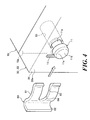
- an attaching portion 11a is formed at the distal end portion of the attaching pin 11.
- a diameter of the attaching portion 11 a is smaller than diameters of portions of the attaching pin 11 that lie on both sides of the attaching portion 11a.
- the attaching portion 11a forms a groove portion on an outer circumferential surface of the distal end portion of the attaching pin 11 along the full circumference thereof.
- the attaching portion 11a is disposed between the front surface 33a of the flange 33 and the outer circumferential portion of the accommodating portion 32, as shown in Fig. 2 , when the flange 33 is butted up against the front surface 10a of the base body 10, however, the end portion of the attaching portion 11 a that faces the base body 10 is disposed within the attaching hole 35 (refer to Fig. 4 ).
- the elastic clip 60 is a bifurcating plate spring that holds the attaching portion 11a of the attaching pin 11 on the front surface 33a of the flange 33.
- the elastic clip 60 has a plate-shaped main body portion 61, and a groove portion 63 is formed to be opened toward one edge portion of the main body portion 61.
- a wall portion 62 is formed at the other edge portion of the main body portion 61 to rise toward the front.
- a groove width of the groove portion 63 of the elastic clip 60 is made slightly larger than an outside diameter of the attaching portion 11a of the attaching pin 11.
- a circular fitting portion 64 is formed in a bottom portion (an inner end portion) of the groove portion 63.
- the fitting portion 64 is a portion that is fitted on the attaching portion 11a.
- the main body portion 61 is curved so as to project to the front.
- the groove portion 63 of the elastic clip 60 is fitted on the attaching portion 11a of the attaching pin 11 as shown in Fig. 5 , the one edge portion and the other edge portion of the main body portion 61 are brought into abutment with the front surface 33a of the flange 33 (at contact points B1, B2 in Fig. 5 ).
- An apex portion between the one edge portion and the other edge portion of the main body portion 61 is brought into abutment with a surface 11c, facing the flange 33, of a head portion 11b of the attaching pin 11 (at a contact point A1 in Fig. 5 ).
- Projecting portions 12 are formed on the front surface 33a of the flange 33.
- the projecting portion 12 is brought into abutment with the other edge portion (the edge portion where the wall portion 62 is provided) of the main body portion 61 when the groove portion 63 of the elastic clip 60 is fitted on the attaching portion 11 a of the attaching pin 11.
- the projecting portion 12 is formed in a straight line and functions to prevent the dislocation and rotation of the elastic clip 60.
- the flange 33 of the housing 30 is butted up against the front surface 10a of the base body 10 while inserting the attaching pins 11 on the base body 10 into the attaching holes 35 in the flange 33.
- the elastic clips 60 are inserted in the space between the front surface 33a of the flange 33 and the outer circumferential portion of the accommodating portion 32 from sides of the base body 10, and as shown in Fig. 5 , the groove portions 63 of the elastic clips 60 are fitted on the attaching portion 11a of the attaching pins 11.
- the elastic clip 60 rides over the projecting portion 12 to move further.
- a force is designed to be applied easily to the elastic clip 60 by pushing the wall portion 62 of the main body portion 61.
- the attaching portion 11 a of the attaching pin 11 is fitted in the fitting portion 64 of the elastic clip 60 so that the attaching portion 11a is held by the elastic clip 60, the main body portion 61 of the elastic clip 60 is elastically engaged between the front surface 33a of the flange 33 and the head portion 11b of the attaching pin 11.
- the accommodating portion 32 of the housing 30 can also be made to project in the position where the accommodating portion 32 covers the attaching holes 35 in the flange 33. Consequently, as shown in Fig. 1A , since the capacity of the accommodating portion 32 that accommodates the control circuit board 20 can be increased, even though the control circuit board is increased in size as the brakes tend to be controlled in multiple ways, the control circuit board 20 can be accommodated in the housing 30.
- the elastic clip 60 is the plate spring and its thickness is thin. Therefore, as shown in Fig. 2 , the space between the flange 33 and the accommodating portion 32 can be made small, thereby reducing the housing 30 in size in relation to the height direction.
- the housing 30 can be attached to or detached from the base body 10 in such a state that the control circuit board 20 is kept attached within the housing. Further, the elastic clips 60 can be attached to or detached from the attaching pins 11 from the sides of the base body 10. Consequently, the fabrication and maintenance of the vehicle brake hydraulic pressure control unit 1 can be facilitated.
- the single plate-shaped elastic clip 60 is attached to the attaching pin 11.
- a plate spring may be used that is formed by bending a single plate into a U-shape to provide two front and rear flat plate portions.
- a rubber member or a coil spring can also be used as the elastic member.
- the electronic control unit is applied to the vehicle brake hydraulic pressure control unit 1.
- the electronic control unit of the invention can also be applied to various types of control units.
Landscapes
- Engineering & Computer Science (AREA)
- Physics & Mathematics (AREA)
- Electromagnetism (AREA)
- Mechanical Engineering (AREA)
- Transportation (AREA)
- Fluid Mechanics (AREA)
- Regulating Braking Force (AREA)
- Snaps, Bayonet Connections, Set Pins, And Snap Rings (AREA)
- Mounting Of Printed Circuit Boards And The Like (AREA)
Applications Claiming Priority (1)
| Application Number | Priority Date | Filing Date | Title |
|---|---|---|---|
| JP2013237526A JP6007357B2 (ja) | 2013-11-18 | 2013-11-18 | 電子制御装置および車両用ブレーキ液圧制御装置 |
Publications (2)
| Publication Number | Publication Date |
|---|---|
| EP2886408A1 true EP2886408A1 (de) | 2015-06-24 |
| EP2886408B1 EP2886408B1 (de) | 2017-03-15 |
Family
ID=52020928
Family Applications (1)
| Application Number | Title | Priority Date | Filing Date |
|---|---|---|---|
| EP14193424.0A Not-in-force EP2886408B1 (de) | 2013-11-18 | 2014-11-17 | Elektronische steuerungseinheit und hydraulikdrucksteuerungseinheit für fahrzeugbremse |
Country Status (4)
| Country | Link |
|---|---|
| US (1) | US9592799B2 (de) |
| EP (1) | EP2886408B1 (de) |
| JP (1) | JP6007357B2 (de) |
| CN (1) | CN104661475B (de) |
Families Citing this family (66)
| Publication number | Priority date | Publication date | Assignee | Title |
|---|---|---|---|---|
| US9060770B2 (en) | 2003-05-20 | 2015-06-23 | Ethicon Endo-Surgery, Inc. | Robotically-driven surgical instrument with E-beam driver |
| US20070084897A1 (en) | 2003-05-20 | 2007-04-19 | Shelton Frederick E Iv | Articulating surgical stapling instrument incorporating a two-piece e-beam firing mechanism |
| US9072535B2 (en) | 2011-05-27 | 2015-07-07 | Ethicon Endo-Surgery, Inc. | Surgical stapling instruments with rotatable staple deployment arrangements |
| US8365976B2 (en) | 2006-09-29 | 2013-02-05 | Ethicon Endo-Surgery, Inc. | Surgical staples having dissolvable, bioabsorbable or biofragmentable portions and stapling instruments for deploying the same |
| US10159482B2 (en) | 2005-08-31 | 2018-12-25 | Ethicon Llc | Fastener cartridge assembly comprising a fixed anvil and different staple heights |
| US20070106317A1 (en) | 2005-11-09 | 2007-05-10 | Shelton Frederick E Iv | Hydraulically and electrically actuated articulation joints for surgical instruments |
| US20120292367A1 (en) | 2006-01-31 | 2012-11-22 | Ethicon Endo-Surgery, Inc. | Robotically-controlled end effector |
| US7753904B2 (en) | 2006-01-31 | 2010-07-13 | Ethicon Endo-Surgery, Inc. | Endoscopic surgical instrument with a handle that can articulate with respect to the shaft |
| US20110295295A1 (en) | 2006-01-31 | 2011-12-01 | Ethicon Endo-Surgery, Inc. | Robotically-controlled surgical instrument having recording capabilities |
| US7845537B2 (en) | 2006-01-31 | 2010-12-07 | Ethicon Endo-Surgery, Inc. | Surgical instrument having recording capabilities |
| US8992422B2 (en) | 2006-03-23 | 2015-03-31 | Ethicon Endo-Surgery, Inc. | Robotically-controlled endoscopic accessory channel |
| US20070225562A1 (en) | 2006-03-23 | 2007-09-27 | Ethicon Endo-Surgery, Inc. | Articulating endoscopic accessory channel |
| US8840603B2 (en) | 2007-01-10 | 2014-09-23 | Ethicon Endo-Surgery, Inc. | Surgical instrument with wireless communication between control unit and sensor transponders |
| US8684253B2 (en) | 2007-01-10 | 2014-04-01 | Ethicon Endo-Surgery, Inc. | Surgical instrument with wireless communication between a control unit of a robotic system and remote sensor |
| US7673782B2 (en) | 2007-03-15 | 2010-03-09 | Ethicon Endo-Surgery, Inc. | Surgical stapling instrument having a releasable buttress material |
| US8931682B2 (en) | 2007-06-04 | 2015-01-13 | Ethicon Endo-Surgery, Inc. | Robotically-controlled shaft based rotary drive systems for surgical instruments |
| US7866527B2 (en) | 2008-02-14 | 2011-01-11 | Ethicon Endo-Surgery, Inc. | Surgical stapling apparatus with interlockable firing system |
| US7819298B2 (en) | 2008-02-14 | 2010-10-26 | Ethicon Endo-Surgery, Inc. | Surgical stapling apparatus with control features operable with one hand |
| US8573465B2 (en) | 2008-02-14 | 2013-11-05 | Ethicon Endo-Surgery, Inc. | Robotically-controlled surgical end effector system with rotary actuated closure systems |
| US9386983B2 (en) | 2008-09-23 | 2016-07-12 | Ethicon Endo-Surgery, Llc | Robotically-controlled motorized surgical instrument |
| AU2011308701B2 (en) | 2010-09-30 | 2013-11-14 | Ethicon Endo-Surgery, Inc. | Fastener system comprising a retention matrix and an alignment matrix |
| US9301753B2 (en) | 2010-09-30 | 2016-04-05 | Ethicon Endo-Surgery, Llc | Expandable tissue thickness compensator |
| US9386988B2 (en) | 2010-09-30 | 2016-07-12 | Ethicon End-Surgery, LLC | Retainer assembly including a tissue thickness compensator |
| US9480476B2 (en) | 2010-09-30 | 2016-11-01 | Ethicon Endo-Surgery, Llc | Tissue thickness compensator comprising resilient members |
| US8746535B2 (en) | 2010-09-30 | 2014-06-10 | Ethicon Endo-Surgery, Inc. | Tissue thickness compensator comprising detachable portions |
| US9220501B2 (en) | 2010-09-30 | 2015-12-29 | Ethicon Endo-Surgery, Inc. | Tissue thickness compensators |
| US8827903B2 (en) | 2011-03-14 | 2014-09-09 | Ethicon Endo-Surgery, Inc. | Modular tool heads for use with circular surgical instruments |
| BR112013027794B1 (pt) | 2011-04-29 | 2020-12-15 | Ethicon Endo-Surgery, Inc | Conjunto de cartucho de grampos |
| US9044230B2 (en) | 2012-02-13 | 2015-06-02 | Ethicon Endo-Surgery, Inc. | Surgical cutting and fastening instrument with apparatus for determining cartridge and firing motion status |
| JP6105041B2 (ja) | 2012-03-28 | 2017-03-29 | エシコン・エンド−サージェリィ・インコーポレイテッドEthicon Endo−Surgery,Inc. | 低圧環境を画定するカプセルを含む組織厚コンペンセーター |
| MX353040B (es) | 2012-03-28 | 2017-12-18 | Ethicon Endo Surgery Inc | Unidad retenedora que incluye un compensador de grosor de tejido. |
| US9101358B2 (en) | 2012-06-15 | 2015-08-11 | Ethicon Endo-Surgery, Inc. | Articulatable surgical instrument comprising a firing drive |
| US9289256B2 (en) | 2012-06-28 | 2016-03-22 | Ethicon Endo-Surgery, Llc | Surgical end effectors having angled tissue-contacting surfaces |
| US20140005678A1 (en) | 2012-06-28 | 2014-01-02 | Ethicon Endo-Surgery, Inc. | Rotary drive arrangements for surgical instruments |
| US9700310B2 (en) | 2013-08-23 | 2017-07-11 | Ethicon Llc | Firing member retraction devices for powered surgical instruments |
| US9888919B2 (en) | 2013-03-14 | 2018-02-13 | Ethicon Llc | Method and system for operating a surgical instrument |
| US9649110B2 (en) | 2013-04-16 | 2017-05-16 | Ethicon Llc | Surgical instrument comprising a closing drive and a firing drive operated from the same rotatable output |
| US9962161B2 (en) | 2014-02-12 | 2018-05-08 | Ethicon Llc | Deliverable surgical instrument |
| US20140166724A1 (en) | 2014-02-24 | 2014-06-19 | Ethicon Endo-Surgery, Inc. | Staple cartridge including a barbed staple |
| US9743929B2 (en) | 2014-03-26 | 2017-08-29 | Ethicon Llc | Modular powered surgical instrument with detachable shaft assemblies |
| US10004497B2 (en) | 2014-03-26 | 2018-06-26 | Ethicon Llc | Interface systems for use with surgical instruments |
| US10426476B2 (en) | 2014-09-26 | 2019-10-01 | Ethicon Llc | Circular fastener cartridges for applying radially expandable fastener lines |
| US10561422B2 (en) | 2014-04-16 | 2020-02-18 | Ethicon Llc | Fastener cartridge comprising deployable tissue engaging members |
| US10045781B2 (en) | 2014-06-13 | 2018-08-14 | Ethicon Llc | Closure lockout systems for surgical instruments |
| US10111679B2 (en) | 2014-09-05 | 2018-10-30 | Ethicon Llc | Circuitry and sensors for powered medical device |
| US9924944B2 (en) | 2014-10-16 | 2018-03-27 | Ethicon Llc | Staple cartridge comprising an adjunct material |
| US9844376B2 (en) | 2014-11-06 | 2017-12-19 | Ethicon Llc | Staple cartridge comprising a releasable adjunct material |
| US10736636B2 (en) | 2014-12-10 | 2020-08-11 | Ethicon Llc | Articulatable surgical instrument system |
| US9968355B2 (en) | 2014-12-18 | 2018-05-15 | Ethicon Llc | Surgical instruments with articulatable end effectors and improved firing beam support arrangements |
| US9844374B2 (en) | 2014-12-18 | 2017-12-19 | Ethicon Llc | Surgical instrument systems comprising an articulatable end effector and means for adjusting the firing stroke of a firing member |
| US9987000B2 (en) | 2014-12-18 | 2018-06-05 | Ethicon Llc | Surgical instrument assembly comprising a flexible articulation system |
| US9844375B2 (en) | 2014-12-18 | 2017-12-19 | Ethicon Llc | Drive arrangements for articulatable surgical instruments |
| US10159483B2 (en) | 2015-02-27 | 2018-12-25 | Ethicon Llc | Surgical apparatus configured to track an end-of-life parameter |
| US9993258B2 (en) | 2015-02-27 | 2018-06-12 | Ethicon Llc | Adaptable surgical instrument handle |
| US9808246B2 (en) | 2015-03-06 | 2017-11-07 | Ethicon Endo-Surgery, Llc | Method of operating a powered surgical instrument |
| US10052044B2 (en) | 2015-03-06 | 2018-08-21 | Ethicon Llc | Time dependent evaluation of sensor data to determine stability, creep, and viscoelastic elements of measures |
| US9924961B2 (en) | 2015-03-06 | 2018-03-27 | Ethicon Endo-Surgery, Llc | Interactive feedback system for powered surgical instruments |
| US10045776B2 (en) | 2015-03-06 | 2018-08-14 | Ethicon Llc | Control techniques and sub-processor contained within modular shaft with select control processing from handle |
| US9901342B2 (en) | 2015-03-06 | 2018-02-27 | Ethicon Endo-Surgery, Llc | Signal and power communication system positioned on a rotatable shaft |
| JP6481529B2 (ja) | 2015-07-06 | 2019-03-13 | スズキ株式会社 | 慣性センサの取付構造及び自動二輪車 |
| US9868408B2 (en) * | 2016-01-29 | 2018-01-16 | Ford Global Technologies, Llc | Protective cover for vehicular control module |
| US10675024B2 (en) | 2016-06-24 | 2020-06-09 | Ethicon Llc | Staple cartridge comprising overdriven staples |
| USD867239S1 (en) * | 2017-01-31 | 2019-11-19 | Nissin Kogyo Co., Ltd. | Brake control unit |
| JP7319870B2 (ja) * | 2019-08-29 | 2023-08-02 | ロベルト・ボッシュ・ゲゼルシャフト・ミト・ベシュレンクテル・ハフツング | 液圧制御ユニット、ブレーキシステム及び鞍乗型車両 |
| US12077110B2 (en) * | 2021-06-29 | 2024-09-03 | Apple Inc. | Consolidated electronics packaging |
| DE102021125953A1 (de) | 2021-10-06 | 2023-04-06 | Knorr-Bremse Systeme für Schienenfahrzeuge GmbH | Bremsbelag für eine Teilbelag-Scheibenbremse eines Schienenfahrzeugs und Anordnung eines Bremsbelags einer Teilbelag-Scheibenbremse eines Schienenfahrzeuges an einem Belaghalter |
Citations (6)
| Publication number | Priority date | Publication date | Assignee | Title |
|---|---|---|---|---|
| JPH1143032A (ja) * | 1997-07-30 | 1999-02-16 | Unisia Jecs Corp | 電極接続ロッド固定構造 |
| US6634723B1 (en) * | 1999-09-10 | 2003-10-21 | Kelsey-Hayes Company | Electro-hydraulic control unit for an electronic brake control system |
| JP2004039948A (ja) | 2002-07-05 | 2004-02-05 | Nissin Kogyo Co Ltd | 制御基板の支持構造 |
| JP2005294480A (ja) | 2004-03-31 | 2005-10-20 | Nissin Kogyo Co Ltd | プリント配線基板およびプリント配線基板のはんだ付け方法 |
| EP1588913A1 (de) * | 2004-04-20 | 2005-10-26 | SAB WABCO S.p.A. | Elektro-pneumatische Bremsregeleinheit für ein Schienenfahrzeug |
| EP2008895A2 (de) * | 2007-06-28 | 2008-12-31 | Nissin Kogyo Co., Ltd. | Hydraulische Drucksteuereinheit für Fahrzeugbremsen |
Family Cites Families (17)
| Publication number | Priority date | Publication date | Assignee | Title |
|---|---|---|---|---|
| JPS4518407Y1 (de) * | 1964-03-19 | 1970-07-28 | ||
| WO1989005746A1 (fr) * | 1987-12-14 | 1989-06-29 | Alfred Teves Gmbh | Ensemble d'appareils de distribution et de regulation groupes |
| JPH09193788A (ja) * | 1996-01-22 | 1997-07-29 | Nisshinbo Ind Inc | ブレーキ圧力制御装置 |
| DE19612907A1 (de) * | 1996-03-30 | 1997-10-02 | Teves Gmbh Alfred | Reglereinheit |
| JP3740652B2 (ja) * | 1997-07-25 | 2006-02-01 | 三菱電機株式会社 | 電気機器のケース |
| GB9802058D0 (en) * | 1998-01-31 | 1998-03-25 | Mckechnie Uk Ltd | Fixing articles together |
| US6354674B1 (en) * | 1998-12-11 | 2002-03-12 | Denso Corporation | Hydraulic control apparatus integrated with motor driving circuit unit |
| DE10108208A1 (de) * | 2001-02-21 | 2002-08-22 | Bosch Gmbh Robert | Elektrohydraulische Druckregelvorrichtung |
| JP2004168281A (ja) * | 2002-10-29 | 2004-06-17 | Advics:Kk | 液圧ブレーキ装置 |
| JP4239770B2 (ja) * | 2003-09-17 | 2009-03-18 | 株式会社アドヴィックス | 液圧制御装置の一体化構造 |
| CN2763875Y (zh) * | 2004-11-30 | 2006-03-08 | 鸿富锦精密工业(深圳)有限公司 | 电路板固定装置 |
| JP4715183B2 (ja) * | 2004-12-13 | 2011-07-06 | 株式会社アドヴィックス | ブレーキ液圧による車両制御装置 |
| JP4637926B2 (ja) * | 2008-03-28 | 2011-02-23 | 日立オートモティブシステムズ株式会社 | 電子装置および液圧ユニット |
| JP4669553B2 (ja) * | 2008-05-27 | 2011-04-13 | 日信工業株式会社 | 電子制御ユニット及び車両挙動制御装置 |
| US9061666B2 (en) * | 2009-09-15 | 2015-06-23 | Nissin Kogyo Co., Ltd. | Electronic control unit assembling method, electronic control unit and vehicle brake hydraulic pressure control apparatus |
| GB2474509A (en) * | 2009-10-19 | 2011-04-20 | Psm Internat Ltd | A fastener system for an LCD TV Display |
| CN102910162A (zh) * | 2011-08-04 | 2013-02-06 | 日立汽车系统株式会社 | 电子控制装置 |
-
2013
- 2013-11-18 JP JP2013237526A patent/JP6007357B2/ja not_active Expired - Fee Related
-
2014
- 2014-11-14 US US14/541,958 patent/US9592799B2/en not_active Expired - Fee Related
- 2014-11-17 EP EP14193424.0A patent/EP2886408B1/de not_active Not-in-force
- 2014-11-18 CN CN201410655403.XA patent/CN104661475B/zh not_active Expired - Fee Related
Patent Citations (8)
| Publication number | Priority date | Publication date | Assignee | Title |
|---|---|---|---|---|
| JPH1143032A (ja) * | 1997-07-30 | 1999-02-16 | Unisia Jecs Corp | 電極接続ロッド固定構造 |
| US6634723B1 (en) * | 1999-09-10 | 2003-10-21 | Kelsey-Hayes Company | Electro-hydraulic control unit for an electronic brake control system |
| JP2004039948A (ja) | 2002-07-05 | 2004-02-05 | Nissin Kogyo Co Ltd | 制御基板の支持構造 |
| US20040074536A1 (en) * | 2002-07-05 | 2004-04-22 | Motoyasu Nakamura | Support structure of control board |
| JP2005294480A (ja) | 2004-03-31 | 2005-10-20 | Nissin Kogyo Co Ltd | プリント配線基板およびプリント配線基板のはんだ付け方法 |
| EP1588913A1 (de) * | 2004-04-20 | 2005-10-26 | SAB WABCO S.p.A. | Elektro-pneumatische Bremsregeleinheit für ein Schienenfahrzeug |
| EP2008895A2 (de) * | 2007-06-28 | 2008-12-31 | Nissin Kogyo Co., Ltd. | Hydraulische Drucksteuereinheit für Fahrzeugbremsen |
| JP2009006855A (ja) | 2007-06-28 | 2009-01-15 | Nissin Kogyo Co Ltd | 車両用ブレーキ液圧制御装置 |
Also Published As
| Publication number | Publication date |
|---|---|
| CN104661475A (zh) | 2015-05-27 |
| JP2015098187A (ja) | 2015-05-28 |
| US20150137589A1 (en) | 2015-05-21 |
| JP6007357B2 (ja) | 2016-10-12 |
| CN104661475B (zh) | 2018-10-19 |
| EP2886408B1 (de) | 2017-03-15 |
| US9592799B2 (en) | 2017-03-14 |
Similar Documents
| Publication | Publication Date | Title |
|---|---|---|
| EP2886408B1 (de) | Elektronische steuerungseinheit und hydraulikdrucksteuerungseinheit für fahrzeugbremse | |
| US10407038B2 (en) | Hydraulic pressure generating apparatus | |
| EP2008895B1 (de) | Hydraulische Drucksteuereinheit für Fahrzeugbremsen | |
| CN103786711B (zh) | 电子制动系统用ecu和电磁阀的线圈组件的结构总成 | |
| US20100019186A1 (en) | Engine valve assembly with valve can mountable to an engine cover | |
| JP4669553B2 (ja) | 電子制御ユニット及び車両挙動制御装置 | |
| JP2009029239A (ja) | 電子制御ユニット及び車両挙動制御装置 | |
| US11247654B2 (en) | Electrical component assembly and vehicular brake fluid pressure control device | |
| US9899983B2 (en) | Electronic control unit | |
| CN105818794A (zh) | 线圈组件 | |
| CN110383402A (zh) | 电气零部件组装体和车辆用制动液压控制装置 | |
| JP6233897B2 (ja) | 圧力センサ | |
| JP2017020480A (ja) | キャニスタ | |
| JP2009029240A (ja) | 電子制御ユニット及び車両挙動制御装置 | |
| CN110382314A (zh) | 电气零部件组装体和车辆用制动液压控制装置 | |
| JP2015532418A (ja) | 圧力センサ | |
| US9499146B2 (en) | Hydraulic braking device | |
| JP4848033B2 (ja) | 電子制御ユニットの組付方法、電子制御ユニットおよび車両用ブレーキ液圧制御装置 | |
| JP6791791B2 (ja) | 電子制御装置およびブレーキ液圧制御装置 | |
| JP6422071B2 (ja) | 電子制御ユニットおよび車両用ブレーキ液圧制御装置 | |
| JP2009040125A (ja) | 電子制御ユニット及び車両挙動制御装置 | |
| US20150239443A1 (en) | Actuator for brake fluid pressure control | |
| KR20200028936A (ko) | 압력 매체 조립체 | |
| JP2011073634A (ja) | 車両用ブレーキ液圧制御装置 | |
| JPS5915054Y2 (ja) | 電磁石 |
Legal Events
| Date | Code | Title | Description |
|---|---|---|---|
| PUAI | Public reference made under article 153(3) epc to a published international application that has entered the european phase |
Free format text: ORIGINAL CODE: 0009012 |
|
| 17P | Request for examination filed |
Effective date: 20141117 |
|
| AK | Designated contracting states |
Kind code of ref document: A1 Designated state(s): AL AT BE BG CH CY CZ DE DK EE ES FI FR GB GR HR HU IE IS IT LI LT LU LV MC MK MT NL NO PL PT RO RS SE SI SK SM TR |
|
| AX | Request for extension of the european patent |
Extension state: BA ME |
|
| R17P | Request for examination filed (corrected) |
Effective date: 20151124 |
|
| RBV | Designated contracting states (corrected) |
Designated state(s): AL AT BE BG CH CY CZ DE DK EE ES FI FR GB GR HR HU IE IS IT LI LT LU LV MC MK MT NL NO PL PT RO RS SE SI SK SM TR |
|
| RAP1 | Party data changed (applicant data changed or rights of an application transferred) |
Owner name: AUTOLIV NISSIN BRAKE SYSTEMS JAPAN CO., LTD. |
|
| GRAP | Despatch of communication of intention to grant a patent |
Free format text: ORIGINAL CODE: EPIDOSNIGR1 |
|
| INTG | Intention to grant announced |
Effective date: 20161005 |
|
| GRAS | Grant fee paid |
Free format text: ORIGINAL CODE: EPIDOSNIGR3 |
|
| GRAA | (expected) grant |
Free format text: ORIGINAL CODE: 0009210 |
|
| AK | Designated contracting states |
Kind code of ref document: B1 Designated state(s): AL AT BE BG CH CY CZ DE DK EE ES FI FR GB GR HR HU IE IS IT LI LT LU LV MC MK MT NL NO PL PT RO RS SE SI SK SM TR |
|
| REG | Reference to a national code |
Ref country code: CH Ref legal event code: EP Ref country code: GB Ref legal event code: FG4D |
|
| REG | Reference to a national code |
Ref country code: IE Ref legal event code: FG4D |
|
| REG | Reference to a national code |
Ref country code: AT Ref legal event code: REF Ref document number: 875191 Country of ref document: AT Kind code of ref document: T Effective date: 20170415 |
|
| REG | Reference to a national code |
Ref country code: DE Ref legal event code: R096 Ref document number: 602014007556 Country of ref document: DE |
|
| REG | Reference to a national code |
Ref country code: NL Ref legal event code: MP Effective date: 20170315 |
|
| REG | Reference to a national code |
Ref country code: LT Ref legal event code: MG4D |
|
| PG25 | Lapsed in a contracting state [announced via postgrant information from national office to epo] |
Ref country code: NO Free format text: LAPSE BECAUSE OF FAILURE TO SUBMIT A TRANSLATION OF THE DESCRIPTION OR TO PAY THE FEE WITHIN THE PRESCRIBED TIME-LIMIT Effective date: 20170615 Ref country code: FI Free format text: LAPSE BECAUSE OF FAILURE TO SUBMIT A TRANSLATION OF THE DESCRIPTION OR TO PAY THE FEE WITHIN THE PRESCRIBED TIME-LIMIT Effective date: 20170315 Ref country code: GR Free format text: LAPSE BECAUSE OF FAILURE TO SUBMIT A TRANSLATION OF THE DESCRIPTION OR TO PAY THE FEE WITHIN THE PRESCRIBED TIME-LIMIT Effective date: 20170616 Ref country code: HR Free format text: LAPSE BECAUSE OF FAILURE TO SUBMIT A TRANSLATION OF THE DESCRIPTION OR TO PAY THE FEE WITHIN THE PRESCRIBED TIME-LIMIT Effective date: 20170315 Ref country code: LT Free format text: LAPSE BECAUSE OF FAILURE TO SUBMIT A TRANSLATION OF THE DESCRIPTION OR TO PAY THE FEE WITHIN THE PRESCRIBED TIME-LIMIT Effective date: 20170315 |
|
| REG | Reference to a national code |
Ref country code: AT Ref legal event code: MK05 Ref document number: 875191 Country of ref document: AT Kind code of ref document: T Effective date: 20170315 |
|
| PG25 | Lapsed in a contracting state [announced via postgrant information from national office to epo] |
Ref country code: RS Free format text: LAPSE BECAUSE OF FAILURE TO SUBMIT A TRANSLATION OF THE DESCRIPTION OR TO PAY THE FEE WITHIN THE PRESCRIBED TIME-LIMIT Effective date: 20170315 Ref country code: BG Free format text: LAPSE BECAUSE OF FAILURE TO SUBMIT A TRANSLATION OF THE DESCRIPTION OR TO PAY THE FEE WITHIN THE PRESCRIBED TIME-LIMIT Effective date: 20170615 Ref country code: LV Free format text: LAPSE BECAUSE OF FAILURE TO SUBMIT A TRANSLATION OF THE DESCRIPTION OR TO PAY THE FEE WITHIN THE PRESCRIBED TIME-LIMIT Effective date: 20170315 Ref country code: SE Free format text: LAPSE BECAUSE OF FAILURE TO SUBMIT A TRANSLATION OF THE DESCRIPTION OR TO PAY THE FEE WITHIN THE PRESCRIBED TIME-LIMIT Effective date: 20170315 |
|
| PG25 | Lapsed in a contracting state [announced via postgrant information from national office to epo] |
Ref country code: NL Free format text: LAPSE BECAUSE OF FAILURE TO SUBMIT A TRANSLATION OF THE DESCRIPTION OR TO PAY THE FEE WITHIN THE PRESCRIBED TIME-LIMIT Effective date: 20170315 |
|
| REG | Reference to a national code |
Ref country code: FR Ref legal event code: PLFP Year of fee payment: 4 |
|
| PG25 | Lapsed in a contracting state [announced via postgrant information from national office to epo] |
Ref country code: RO Free format text: LAPSE BECAUSE OF FAILURE TO SUBMIT A TRANSLATION OF THE DESCRIPTION OR TO PAY THE FEE WITHIN THE PRESCRIBED TIME-LIMIT Effective date: 20170315 Ref country code: EE Free format text: LAPSE BECAUSE OF FAILURE TO SUBMIT A TRANSLATION OF THE DESCRIPTION OR TO PAY THE FEE WITHIN THE PRESCRIBED TIME-LIMIT Effective date: 20170315 Ref country code: CZ Free format text: LAPSE BECAUSE OF FAILURE TO SUBMIT A TRANSLATION OF THE DESCRIPTION OR TO PAY THE FEE WITHIN THE PRESCRIBED TIME-LIMIT Effective date: 20170315 Ref country code: SK Free format text: LAPSE BECAUSE OF FAILURE TO SUBMIT A TRANSLATION OF THE DESCRIPTION OR TO PAY THE FEE WITHIN THE PRESCRIBED TIME-LIMIT Effective date: 20170315 Ref country code: AT Free format text: LAPSE BECAUSE OF FAILURE TO SUBMIT A TRANSLATION OF THE DESCRIPTION OR TO PAY THE FEE WITHIN THE PRESCRIBED TIME-LIMIT Effective date: 20170315 Ref country code: ES Free format text: LAPSE BECAUSE OF FAILURE TO SUBMIT A TRANSLATION OF THE DESCRIPTION OR TO PAY THE FEE WITHIN THE PRESCRIBED TIME-LIMIT Effective date: 20170315 Ref country code: IT Free format text: LAPSE BECAUSE OF FAILURE TO SUBMIT A TRANSLATION OF THE DESCRIPTION OR TO PAY THE FEE WITHIN THE PRESCRIBED TIME-LIMIT Effective date: 20170315 |
|
| PG25 | Lapsed in a contracting state [announced via postgrant information from national office to epo] |
Ref country code: SM Free format text: LAPSE BECAUSE OF FAILURE TO SUBMIT A TRANSLATION OF THE DESCRIPTION OR TO PAY THE FEE WITHIN THE PRESCRIBED TIME-LIMIT Effective date: 20170315 Ref country code: PL Free format text: LAPSE BECAUSE OF FAILURE TO SUBMIT A TRANSLATION OF THE DESCRIPTION OR TO PAY THE FEE WITHIN THE PRESCRIBED TIME-LIMIT Effective date: 20170315 Ref country code: IS Free format text: LAPSE BECAUSE OF FAILURE TO SUBMIT A TRANSLATION OF THE DESCRIPTION OR TO PAY THE FEE WITHIN THE PRESCRIBED TIME-LIMIT Effective date: 20170715 Ref country code: PT Free format text: LAPSE BECAUSE OF FAILURE TO SUBMIT A TRANSLATION OF THE DESCRIPTION OR TO PAY THE FEE WITHIN THE PRESCRIBED TIME-LIMIT Effective date: 20170717 |
|
| REG | Reference to a national code |
Ref country code: DE Ref legal event code: R097 Ref document number: 602014007556 Country of ref document: DE |
|
| PLBE | No opposition filed within time limit |
Free format text: ORIGINAL CODE: 0009261 |
|
| STAA | Information on the status of an ep patent application or granted ep patent |
Free format text: STATUS: NO OPPOSITION FILED WITHIN TIME LIMIT |
|
| PG25 | Lapsed in a contracting state [announced via postgrant information from national office to epo] |
Ref country code: DK Free format text: LAPSE BECAUSE OF FAILURE TO SUBMIT A TRANSLATION OF THE DESCRIPTION OR TO PAY THE FEE WITHIN THE PRESCRIBED TIME-LIMIT Effective date: 20170315 |
|
| 26N | No opposition filed |
Effective date: 20171218 |
|
| PG25 | Lapsed in a contracting state [announced via postgrant information from national office to epo] |
Ref country code: SI Free format text: LAPSE BECAUSE OF FAILURE TO SUBMIT A TRANSLATION OF THE DESCRIPTION OR TO PAY THE FEE WITHIN THE PRESCRIBED TIME-LIMIT Effective date: 20170315 |
|
| PG25 | Lapsed in a contracting state [announced via postgrant information from national office to epo] |
Ref country code: MC Free format text: LAPSE BECAUSE OF FAILURE TO SUBMIT A TRANSLATION OF THE DESCRIPTION OR TO PAY THE FEE WITHIN THE PRESCRIBED TIME-LIMIT Effective date: 20170315 |
|
| PG25 | Lapsed in a contracting state [announced via postgrant information from national office to epo] |
Ref country code: CH Free format text: LAPSE BECAUSE OF NON-PAYMENT OF DUE FEES Effective date: 20171130 Ref country code: LI Free format text: LAPSE BECAUSE OF NON-PAYMENT OF DUE FEES Effective date: 20171130 |
|
| PG25 | Lapsed in a contracting state [announced via postgrant information from national office to epo] |
Ref country code: LU Free format text: LAPSE BECAUSE OF NON-PAYMENT OF DUE FEES Effective date: 20171117 |
|
| REG | Reference to a national code |
Ref country code: BE Ref legal event code: MM Effective date: 20171130 |
|
| REG | Reference to a national code |
Ref country code: IE Ref legal event code: MM4A |
|
| PG25 | Lapsed in a contracting state [announced via postgrant information from national office to epo] |
Ref country code: MT Free format text: LAPSE BECAUSE OF NON-PAYMENT OF DUE FEES Effective date: 20171117 |
|
| REG | Reference to a national code |
Ref country code: FR Ref legal event code: PLFP Year of fee payment: 5 |
|
| PG25 | Lapsed in a contracting state [announced via postgrant information from national office to epo] |
Ref country code: IE Free format text: LAPSE BECAUSE OF NON-PAYMENT OF DUE FEES Effective date: 20171117 |
|
| PG25 | Lapsed in a contracting state [announced via postgrant information from national office to epo] |
Ref country code: BE Free format text: LAPSE BECAUSE OF NON-PAYMENT OF DUE FEES Effective date: 20171130 |
|
| PG25 | Lapsed in a contracting state [announced via postgrant information from national office to epo] |
Ref country code: HU Free format text: LAPSE BECAUSE OF FAILURE TO SUBMIT A TRANSLATION OF THE DESCRIPTION OR TO PAY THE FEE WITHIN THE PRESCRIBED TIME-LIMIT; INVALID AB INITIO Effective date: 20141117 |
|
| GBPC | Gb: european patent ceased through non-payment of renewal fee |
Effective date: 20181117 |
|
| PG25 | Lapsed in a contracting state [announced via postgrant information from national office to epo] |
Ref country code: CY Free format text: LAPSE BECAUSE OF FAILURE TO SUBMIT A TRANSLATION OF THE DESCRIPTION OR TO PAY THE FEE WITHIN THE PRESCRIBED TIME-LIMIT Effective date: 20170315 |
|
| PG25 | Lapsed in a contracting state [announced via postgrant information from national office to epo] |
Ref country code: MK Free format text: LAPSE BECAUSE OF FAILURE TO SUBMIT A TRANSLATION OF THE DESCRIPTION OR TO PAY THE FEE WITHIN THE PRESCRIBED TIME-LIMIT Effective date: 20170315 |
|
| PG25 | Lapsed in a contracting state [announced via postgrant information from national office to epo] |
Ref country code: GB Free format text: LAPSE BECAUSE OF NON-PAYMENT OF DUE FEES Effective date: 20181117 |
|
| PG25 | Lapsed in a contracting state [announced via postgrant information from national office to epo] |
Ref country code: TR Free format text: LAPSE BECAUSE OF FAILURE TO SUBMIT A TRANSLATION OF THE DESCRIPTION OR TO PAY THE FEE WITHIN THE PRESCRIBED TIME-LIMIT Effective date: 20170315 |
|
| PG25 | Lapsed in a contracting state [announced via postgrant information from national office to epo] |
Ref country code: AL Free format text: LAPSE BECAUSE OF FAILURE TO SUBMIT A TRANSLATION OF THE DESCRIPTION OR TO PAY THE FEE WITHIN THE PRESCRIBED TIME-LIMIT Effective date: 20170315 |
|
| PGFP | Annual fee paid to national office [announced via postgrant information from national office to epo] |
Ref country code: FR Payment date: 20221118 Year of fee payment: 9 Ref country code: DE Payment date: 20220621 Year of fee payment: 9 |
|
| REG | Reference to a national code |
Ref country code: DE Ref legal event code: R119 Ref document number: 602014007556 Country of ref document: DE |
|
| PG25 | Lapsed in a contracting state [announced via postgrant information from national office to epo] |
Ref country code: DE Free format text: LAPSE BECAUSE OF NON-PAYMENT OF DUE FEES Effective date: 20240601 |
|
| PG25 | Lapsed in a contracting state [announced via postgrant information from national office to epo] |
Ref country code: FR Free format text: LAPSE BECAUSE OF NON-PAYMENT OF DUE FEES Effective date: 20231130 |
|
| PG25 | Lapsed in a contracting state [announced via postgrant information from national office to epo] |
Ref country code: FR Free format text: LAPSE BECAUSE OF NON-PAYMENT OF DUE FEES Effective date: 20231130 Ref country code: DE Free format text: LAPSE BECAUSE OF NON-PAYMENT OF DUE FEES Effective date: 20240601 |