EP2886758A2 - Riegelpufferanordnung - Google Patents
Riegelpufferanordnung Download PDFInfo
- Publication number
- EP2886758A2 EP2886758A2 EP14199589.4A EP14199589A EP2886758A2 EP 2886758 A2 EP2886758 A2 EP 2886758A2 EP 14199589 A EP14199589 A EP 14199589A EP 2886758 A2 EP2886758 A2 EP 2886758A2
- Authority
- EP
- European Patent Office
- Prior art keywords
- buffer
- cavity
- latch
- actuator housing
- housing
- Prior art date
- Legal status (The legal status is an assumption and is not a legal conclusion. Google has not performed a legal analysis and makes no representation as to the accuracy of the status listed.)
- Granted
Links
- 239000000872 buffer Substances 0.000 title claims abstract description 111
- 230000000295 complement effect Effects 0.000 claims description 4
- 238000000034 method Methods 0.000 claims description 3
- 210000000078 claw Anatomy 0.000 description 10
- 239000000463 material Substances 0.000 description 5
- 238000009434 installation Methods 0.000 description 4
- 230000008901 benefit Effects 0.000 description 2
- 230000007246 mechanism Effects 0.000 description 2
- 239000013536 elastomeric material Substances 0.000 description 1
- 238000012986 modification Methods 0.000 description 1
- 230000004048 modification Effects 0.000 description 1
- 230000000717 retained effect Effects 0.000 description 1
Images



Classifications
-
- E—FIXED CONSTRUCTIONS
- E05—LOCKS; KEYS; WINDOW OR DOOR FITTINGS; SAFES
- E05B—LOCKS; ACCESSORIES THEREFOR; HANDCUFFS
- E05B85/00—Details of vehicle locks not provided for in groups E05B77/00 - E05B83/00
- E05B85/02—Lock casings
-
- E—FIXED CONSTRUCTIONS
- E05—LOCKS; KEYS; WINDOW OR DOOR FITTINGS; SAFES
- E05B—LOCKS; ACCESSORIES THEREFOR; HANDCUFFS
- E05B77/00—Vehicle locks characterised by special functions or purposes
- E05B77/36—Noise prevention; Anti-rattling means
- E05B77/38—Cushion elements, elastic guiding elements or holding elements, e.g. for cushioning or damping the impact of the bolt against the striker during closing of the wing
-
- E—FIXED CONSTRUCTIONS
- E05—LOCKS; KEYS; WINDOW OR DOOR FITTINGS; SAFES
- E05B—LOCKS; ACCESSORIES THEREFOR; HANDCUFFS
- E05B79/00—Mounting or connecting vehicle locks or parts thereof
- E05B79/02—Mounting of vehicle locks or parts thereof
- E05B79/08—Mounting of individual lock elements in the lock, e.g. levers
-
- E—FIXED CONSTRUCTIONS
- E05—LOCKS; KEYS; WINDOW OR DOOR FITTINGS; SAFES
- E05B—LOCKS; ACCESSORIES THEREFOR; HANDCUFFS
- E05B81/00—Power-actuated vehicle locks
- E05B81/24—Power-actuated vehicle locks characterised by constructional features of the actuator or the power transmission
- E05B81/32—Details of the actuator transmission
- E05B81/34—Details of the actuator transmission of geared transmissions
-
- Y—GENERAL TAGGING OF NEW TECHNOLOGICAL DEVELOPMENTS; GENERAL TAGGING OF CROSS-SECTIONAL TECHNOLOGIES SPANNING OVER SEVERAL SECTIONS OF THE IPC; TECHNICAL SUBJECTS COVERED BY FORMER USPC CROSS-REFERENCE ART COLLECTIONS [XRACs] AND DIGESTS
- Y10—TECHNICAL SUBJECTS COVERED BY FORMER USPC
- Y10T—TECHNICAL SUBJECTS COVERED BY FORMER US CLASSIFICATION
- Y10T29/00—Metal working
- Y10T29/49—Method of mechanical manufacture
- Y10T29/49826—Assembling or joining
-
- Y—GENERAL TAGGING OF NEW TECHNOLOGICAL DEVELOPMENTS; GENERAL TAGGING OF CROSS-SECTIONAL TECHNOLOGIES SPANNING OVER SEVERAL SECTIONS OF THE IPC; TECHNICAL SUBJECTS COVERED BY FORMER USPC CROSS-REFERENCE ART COLLECTIONS [XRACs] AND DIGESTS
- Y10—TECHNICAL SUBJECTS COVERED BY FORMER USPC
- Y10T—TECHNICAL SUBJECTS COVERED BY FORMER US CLASSIFICATION
- Y10T29/00—Metal working
- Y10T29/49—Method of mechanical manufacture
- Y10T29/49826—Assembling or joining
- Y10T29/4984—Retaining clearance for motion between assembled parts
-
- Y—GENERAL TAGGING OF NEW TECHNOLOGICAL DEVELOPMENTS; GENERAL TAGGING OF CROSS-SECTIONAL TECHNOLOGIES SPANNING OVER SEVERAL SECTIONS OF THE IPC; TECHNICAL SUBJECTS COVERED BY FORMER USPC CROSS-REFERENCE ART COLLECTIONS [XRACs] AND DIGESTS
- Y10—TECHNICAL SUBJECTS COVERED BY FORMER USPC
- Y10T—TECHNICAL SUBJECTS COVERED BY FORMER US CLASSIFICATION
- Y10T292/00—Closure fasteners
- Y10T292/08—Bolts
- Y10T292/1043—Swinging
-
- Y—GENERAL TAGGING OF NEW TECHNOLOGICAL DEVELOPMENTS; GENERAL TAGGING OF CROSS-SECTIONAL TECHNOLOGIES SPANNING OVER SEVERAL SECTIONS OF THE IPC; TECHNICAL SUBJECTS COVERED BY FORMER USPC CROSS-REFERENCE ART COLLECTIONS [XRACs] AND DIGESTS
- Y10—TECHNICAL SUBJECTS COVERED BY FORMER USPC
- Y10T—TECHNICAL SUBJECTS COVERED BY FORMER US CLASSIFICATION
- Y10T292/00—Closure fasteners
- Y10T292/08—Bolts
- Y10T292/1043—Swinging
- Y10T292/1075—Operating means
- Y10T292/1082—Motor
Definitions
- Exemplary embodiments of the present invention relate generally to latch mechanisms and, more particularly, to latch mechanisms including a buffer.
- Latch systems are well known in the art.
- a component such as a vehicle door for example, will have a latch for engaging and cinching onto a striker.
- the latch will have a rotatably mounted fork bolt or claw and a detent or pawl engaged with the claw.
- the claw cooperates with a mouth of a latch housing to pivot between an open and closed position for receiving, engaging, and cinching a striker.
- the claw engages the striker the claw rotates and the pawl travels along a cam surface of the claw to retain the claw in a closed and cinched position.
- Inner and outer manually movable release handles may be operably connected to inner and outer release levers on the latch. To release the latch, the pawl is rotated by responsive movement of either of the inner or outer release levers to disengage the claw.
- Movement of the claw, pawl, the inner or outer release lever, or another component of the latch may also be operated via an actuator.
- a buffer is often mounted to the housing, near the actuator, and is configured to contact a stopper portion of the actuator.
- the buffer limits an amount of movement of the actuator, and therefore the mount of movement of a component coupled to the actuator.
- the buffer is positioned within a bore in the housing. During operation, the buffer may be dislodged from the housing and interfere with the movement of the other components of the latch. Once the buffer has fallen inside the latch, the buffer cannot be easily accessed without dismantling a significant portion of the latch.
- a latch including a buffer, a latch housing, and an actuator housing coupled to the latch housing.
- the buffer includes a center portion and a first side portion.
- the actuator housing includes a cavity having a first opening. The cavity is configured to receive the buffer. When the buffer is installed in the cavity, the center portion of the buffer abuts an interior surface of the cavity and the first side portion of the buffer extends through the first opening into a hollow interior of the actuator housing.
- a method of installing a buffer into an actuator housing including inserting the buffer into a cavity formed in an exterior surface of the actuator housing. When inserted, a center portion of the buffer abuts an interior surface of the cavity and a first side portion of the buffer extends through a first opening of the cavity into a hollow interior of the actuator housing.
- an actuator and buffer assembly is provided as described herein.
- a latch or latch assembly with a buffer is provided as described herein.
- a buffer assembly is provided as described herein.
- a housing cover of a latch assembly having a cavity configured to receive a buffer therein, wherein the buffer and the cavity are configured such that the buffer can only be inserted into the cavity from an exterior of the housing cover and a portion of the buffer is located in an interior of the latch assembly covered by the housing cover when the buffer is inserted into the cavity and wherein the buffer cannot completely pass through into the interior of the latch assembly.
- the latch 20 includes a latch body 22 that may be integrated into a component of a vehicle (not shown), such as the vehicle structure adjacent a door, lift gate, or trunk for example.
- the latch body 22 includes a metallic or plastic latch housing 24, fixed to the component of a vehicle, and including a generally hollow interior 26.
- a plurality of conventional latch components such as a fork bolt or claw, a detent or pawl, and a release lever (not shown) for example, which may be used to retain and release an adjacent component of the vehicle.
- the latch 20 also includes an actuator 21 having an actuator housing 30, which in one non-limiting embodiment may comprise two portions secured to each other or an actuator housing 30 with an actuator housing cover 31 secured thereto.
- the actuator 21 is operatively coupled to the latch such that actuation of the actuator 21 will cause a desired movement of a component of the latch 20 in the latch housing 24 and/or actuator housing 30.
- the housing 30 is fixed to the latch housing 24 in any suitable mannber by, for example in a generally perpendicular orientation as illustrated in FIG. 1 .
- a first end 32 of the actuator housing 30 and the latch housing 24 is coupled with a pin 34, and a second end 36 of the actuator housing 30 includes an opening (not shown) configured to receive a complementary portion of an adjacent wall 38 of the latch housing 24.
- an actuator housing 31 is provided to cover the interior of the actuator components located in the actuator housing 30.
- Actuator housing cover 31 is configured to be secured to actuator housing 30.
- the actuator housing 31 may be configured to cover latch housing 24 as well as actuator housing 30.
- the actuator housing 30 as well as the actuator housing cover 31 may also include a metallic or plastic material and may be formed from the same material or a different material than the latch housing 24.
- the actuator housing 30 defines a generally hollow interior 40 configured to support and a plurality of components.
- a motor 50 including a rotatable shaft 52 is arranged within a cavity (not shown) formed in the hollow interior 40 of the actuator housing 30.
- a worm gear 54 mounted concentrically to the motor shaft 52 is configured to rotate with the shaft 52 in either a first direction or a second, opposite direction.
- a worm wheel 56, mounted to the actuator housing 30 with a support shaft 58, is positioned adjacent to and meshed with the worm gear 54.
- operation of the motor 50 causes the worm gear 54 to engage and rotate the worm wheel 56 in either a clockwise or counter clockwise directions depending upon the direction in which shaft 52 is rotated or alternatively as other components operatively coupled to worm wheel 56 are moved with respect to the latch 20.
- a stop feature 60 such as a rectangular or cylindrical protrusion extends from the planar surface 62 of the worm wheel 56, generally in the direction of the actuator housing 30.
- the stop feature 60 is configured to contact a buffer 70 mounted to the actuator housing 30 adjacent the support shaft 58 of the worm wheel 56.
- the stop feature 60 is configured to contact a first side of the buffer 70, and when the worm wheel 56 rotates in a second, opposite direction, the stop feature 60 is configured to contact a second side of the buffer 70.
- the buffer 70 of the latch 20 is illustrated in more detail.
- the buffer 70 is formed from a hard elastic or plastic material, such as rubber or any other suitable elastomeric material configured to adsorb contact forces from stop feature 60.
- buffer 70 includes a center portion 72 having an integrally formed head 74 and base 76 oriented generally perpendicular to one another to form a T-shape.
- a first side portion 78 configured to contact the stop feature 60 when the worm wheel 56 rotates in a first direction, extends from a first side 80 of the base 76.
- an identical, second side portion 82 configured to be contact the stop feature 60 when the worm wheel 56 rotates in a second direction, extends from a second side 84 of the base 76 such that the buffer 70 is substantially symmetrical about a center plane A generally parallel to the sides 80, 84 of the base 76.
- the first and second side portions 78, 82 are positioned adjacent the end 86 of the base 76, opposite the head 74.
- the shape and contour of the side portions 78, 82 may be selected based on the geometry of the worm wheel 56 and to facilitate engagement between the stop feature 60 and each side portion 78, 82.
- the first and second side portions 78, 82 are described separately, embodiments where the first and second side portions 78, 82 are formed as a single piece are considered to be within the scope of various embodiments of the present invention.
- the first and second side portions 78, 82 are integrally formed with the base 76 of the center portion 72. As illustrated in FIG. 4b , the first and second side portions 78, 82 extend in at least a first direction beyond a planar surface 88 of the center portion 72. The first and second side portions 78, 82 may additionally extend in a second direction beyond an opposite planar surface 90 of the center portion 72 such that the buffer 70 is symmetrical about a central plane B, oriented parallel to the planar surfaces 88, 90 of the center portion 72.
- a specific configuration of the buffer 70 is illustrated and described herein buffers 70 having other geometries and configurations are within the scope of the invention.
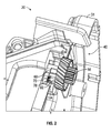
- the actuator housing 30 or housing cover 31 includes a cavity 100 configured to receive and retain the buffer 70 therein.
- the cavity 100 is positioned such that when the buffer 70 is inserted into the cavity 100, end 86 of the center portion 72 is generally adjacent the portion of the actuator housing 30 or housing cover 31 in which the pin 58 configured to support the worm wheel 56 is mounted.
- the shape of the cavity 100 is similar to at least a portion of the buffer 70 such that a portion or portions of the buffer 70 are retained in the cavity 100 due to an interference fit with portions of the buffer 70 when they are received within the cavity 100.
- An interior surface 102 and the shape of the cavity 100 limits movement of the buffer 70 relative to the actuator housing 30 or actuator housing cover 31.
- the interior surface 102 of the cavity 100 prevents the buffer 70 from falling from its installed position into the hollow interior 40 of the actuator housing 30 during operation of the latch 20 and/or installation of the buffer 70 to the latch 20. Moreover, the interior surface 102 and the configuration of the buffer 70 prevent it from being completely inserted into the hollow interior 40 of the actuator housing 30 or actuator housing cover 31 when the buffer 70 is inserted or installed from an outside of the actuator housing 30 or actuator housing cover 31.
- the buffer 70 and the cavity 100 of the actuator housing 30 or actuator housing cover 31 are configured such that the buffer 70 can only be installed from an exterior of the actuator housing 30 or actuator housing cover 31 such that should the buffer 70 become dislodged or removed from the latch 20 it will not be able to fall into the interior of the latch 20 and disrupt operation of components of the latch 20 and/or operation of the latch 20 itself.
- the buffer 70 and the cavity 100 of the actuator housing 30 or actuator housing cover 31 are configured such that during installation of the buffer 70 into cavity 100, the buffer 70 cannot be accidentally pushed into the hollow interior 40 of the actuator housing 30 or actuator housing cover 31 of the latch 20 when they are secured to each other and the buffer 70 is installed into the actuator housing 30 or actuator housing cover 31 of the latch 20. See for example, FIG.
- the cavity 100 is illustrated in actuator cover 31, it is understood that the cavity may be located in anyone of the actuator housing 30, actuator cover 31, latch housing 24 and its associated cover which may or may not be integral with actuator cover 31 or any other desired location.
- multiple cavities and buffers e.g., more than one
- a single cavity 100 and buffer 70 may be employed.
- the cavity 100 includes a first opening 104 and a second opening 106 extending through the actuator housing 30.
- Each of the first opening 104 and the second opening 106 are configured to receive a portion of the buffer 70, for example the first and second side portions 78, 82, respectively.
- the position of the openings 104, 106 relative to the cavity 100 is determined by the portion of the buffer 70 that each opening 104, 106 is configured to receive.
- the first opening 104 and the second opening 106 are arranged adjacent opposing sides of the cavity 100, in a position complementary to the first and second side 78, 82 portions of the buffer 70.
- the planar surface 88 of the center portion 72 of the buffer 70 contacts the interior surface 102 of the cavity 100 and the side portions 78, 82 of the buffer 70 extend through the openings 104, 106.
- the interior surface 102 of the cavity 100 is configured to cover the planar surface 88 of the center portion 72.
- the side portions 78, 82 are exposed within the hollow interior 40 of the actuator housing 30 to contact the stop feature 60 of the adjacent the worm wheel 56 as it rotates.
- the actuator housing 30 and actuator housing cover 31 described herein allows for easy installation of the buffer 70 into the cavity 100 only from the outside of the actuator housing 30 or housing cover 31.
- the complementary contour of the buffer 70 and the cavity 100, as well as the interior surface 102 of the cavity 100, prevents dislocation of the buffer 70 into the latch 20 or actuator during installation of the buffer 70 as well as during operation of the latch 20 and/or the actuator of the latch.
Landscapes
- Lock And Its Accessories (AREA)
Applications Claiming Priority (1)
| Application Number | Priority Date | Filing Date | Title |
|---|---|---|---|
| US201361919282P | 2013-12-20 | 2013-12-20 |
Publications (3)
| Publication Number | Publication Date |
|---|---|
| EP2886758A2 true EP2886758A2 (de) | 2015-06-24 |
| EP2886758A3 EP2886758A3 (de) | 2016-07-20 |
| EP2886758B1 EP2886758B1 (de) | 2018-08-15 |
Family
ID=52338889
Family Applications (1)
| Application Number | Title | Priority Date | Filing Date |
|---|---|---|---|
| EP14199589.4A Not-in-force EP2886758B1 (de) | 2013-12-20 | 2014-12-22 | Riegelpufferanordnung |
Country Status (2)
| Country | Link |
|---|---|
| US (1) | US9758995B2 (de) |
| EP (1) | EP2886758B1 (de) |
Cited By (1)
| Publication number | Priority date | Publication date | Assignee | Title |
|---|---|---|---|---|
| GB2526685A (en) * | 2014-04-24 | 2015-12-02 | Aisin Seiki | Vehicle door lock apparatus |
Families Citing this family (4)
| Publication number | Priority date | Publication date | Assignee | Title |
|---|---|---|---|---|
| JP6364650B2 (ja) * | 2014-08-05 | 2018-08-01 | 三井金属アクト株式会社 | ドアラッチ用アクチュエータ |
| JP6550838B2 (ja) * | 2015-03-27 | 2019-07-31 | アイシン精機株式会社 | 車両用ドアロック装置 |
| US12031360B2 (en) | 2021-02-26 | 2024-07-09 | Deere & Company | Door latch assembly for a work machine |
| US20240200368A1 (en) * | 2022-12-20 | 2024-06-20 | Trimark Corporation | Rotary latch with dampening and barrel retention |
Family Cites Families (15)
| Publication number | Priority date | Publication date | Assignee | Title |
|---|---|---|---|---|
| DE2725345C2 (de) * | 1977-06-04 | 1985-05-23 | Daimler-Benz Ag, 7000 Stuttgart | Aus einem Stahlblechzuschnitt gebogener Schließkloben für einen Kraftfahr-Türverschluß |
| US4186952A (en) * | 1978-07-27 | 1980-02-05 | Keystone Consolidated Industries, Inc. | Turn button latch |
| GB2172753B (en) * | 1985-03-21 | 1989-01-05 | Delco Prod Overseas | Lockable electrically-operable actuator |
| US4679836A (en) * | 1986-03-21 | 1987-07-14 | General Motors Corporation | Closure latch |
| CA1310031C (en) * | 1988-03-31 | 1992-11-10 | Wolfgang Thau | Latch housing & striker for being secured in the latch housing |
| US6572159B2 (en) * | 2000-05-03 | 2003-06-03 | Kiekert Ag | Damped actuating system for motor-vehicle door latch |
| DE10220732A1 (de) * | 2002-05-08 | 2003-12-24 | Brose Schliesssysteme Gmbh | Kraftfahrzeug-Türschloß oder -Klappenschloß |
| US7246840B2 (en) * | 2003-01-31 | 2007-07-24 | Valeo Electrical Systems, Inc. | Vehicle liftgate window component module |
| US7780205B2 (en) * | 2003-05-08 | 2010-08-24 | Kiekert Ag | Motor vehicle door lock |
| JP4418319B2 (ja) | 2004-07-27 | 2010-02-17 | 株式会社大井製作所 | 自動車用ドアラッチ装置 |
| DE102009032894A1 (de) * | 2009-07-13 | 2011-01-20 | Kiekert Ag | Schloss für eine Tür oder eine Klappe an einem Kraftfahrzeug |
| US8348309B2 (en) * | 2010-11-22 | 2013-01-08 | Ford Global Technologies, Llc | Energy absorbing bumper for latch closing sound quality |
| DE102012025009A1 (de) | 2011-12-23 | 2013-06-27 | Magna Closures S.P.A. | System zum Feststellen des Betriebszustands eines Schlosses für eine Tür eines Kraftfahrzeugs und Verfahren zum Zusammensetzen dieses Systems |
| US10094147B2 (en) | 2012-04-13 | 2018-10-09 | Inteva Products, Llc | Rear compartment latch with power and manual release mechanism |
| DE102013009225A1 (de) * | 2013-05-31 | 2014-12-04 | Kiekert Aktiengesellschaft | Bowdenzuglager für ein Kraftfahrzeugschloss |
-
2014
- 2014-12-19 US US14/577,921 patent/US9758995B2/en not_active Expired - Fee Related
- 2014-12-22 EP EP14199589.4A patent/EP2886758B1/de not_active Not-in-force
Non-Patent Citations (1)
| Title |
|---|
| None |
Cited By (2)
| Publication number | Priority date | Publication date | Assignee | Title |
|---|---|---|---|---|
| GB2526685A (en) * | 2014-04-24 | 2015-12-02 | Aisin Seiki | Vehicle door lock apparatus |
| GB2526685B (en) * | 2014-04-24 | 2016-09-14 | Aisin Seiki | Vehicle door lock apparatus |
Also Published As
| Publication number | Publication date |
|---|---|
| EP2886758A3 (de) | 2016-07-20 |
| EP2886758B1 (de) | 2018-08-15 |
| US9758995B2 (en) | 2017-09-12 |
| US20150184430A1 (en) | 2015-07-02 |
Similar Documents
| Publication | Publication Date | Title |
|---|---|---|
| EP1724424B1 (de) | Fahrzeugtürschloss | |
| US9758995B2 (en) | Latch buffer assembly | |
| CN106143648B (zh) | 集成推压开启器的致动机构 | |
| US10472863B2 (en) | Lock with accumulator lever for a motor vehicle | |
| CN104863437B (zh) | 用于机动车辆的门的闩锁 | |
| CN111608518B (zh) | 用于以致动器方式打开盖的致动装置 | |
| CN105003133B (zh) | 用于机动车辆的门的闩锁 | |
| JP6307738B2 (ja) | パネル又はドア用ロック | |
| US10920463B2 (en) | Side door occupant latch with manual release and power lock | |
| US11274474B2 (en) | Motor vehicle lock | |
| US20160130845A1 (en) | Outside handle device for vehicle | |
| KR102178772B1 (ko) | 자동차 로킹 장치 | |
| EP3073036A1 (de) | Türverriegelungsvorrichtung für ein fahrzeug | |
| CN106193847B (zh) | 用于车辆的门锁栓装置 | |
| CN106481153A (zh) | 可调式泄压闩锁 | |
| US20160108653A1 (en) | Detent mechanism for a motor vehicle component | |
| US9534426B2 (en) | Child protector mechanism | |
| CN204715938U (zh) | 车用门锁装置 | |
| KR101798310B1 (ko) | 차량용 핸들 장치 | |
| US11384563B2 (en) | Spring retaining assembly for vehicle latch actuator mechanism | |
| KR101943121B1 (ko) | 차량 도어 록킹 장치 | |
| JP6306490B2 (ja) | 車両用ドアハンドル装置 | |
| US10731386B2 (en) | Lock for a motor vehicle | |
| US11680430B2 (en) | Linear cinching spindle |
Legal Events
| Date | Code | Title | Description |
|---|---|---|---|
| PUAI | Public reference made under article 153(3) epc to a published international application that has entered the european phase |
Free format text: ORIGINAL CODE: 0009012 |
|
| 17P | Request for examination filed |
Effective date: 20141222 |
|
| AK | Designated contracting states |
Kind code of ref document: A2 Designated state(s): AL AT BE BG CH CY CZ DE DK EE ES FI FR GB GR HR HU IE IS IT LI LT LU LV MC MK MT NL NO PL PT RO RS SE SI SK SM TR |
|
| AX | Request for extension of the european patent |
Extension state: BA ME |
|
| PUAL | Search report despatched |
Free format text: ORIGINAL CODE: 0009013 |
|
| AK | Designated contracting states |
Kind code of ref document: A3 Designated state(s): AL AT BE BG CH CY CZ DE DK EE ES FI FR GB GR HR HU IE IS IT LI LT LU LV MC MK MT NL NO PL PT RO RS SE SI SK SM TR |
|
| AX | Request for extension of the european patent |
Extension state: BA ME |
|
| RIC1 | Information provided on ipc code assigned before grant |
Ipc: E05B 85/02 20140101ALI20160614BHEP Ipc: E05B 77/38 20140101AFI20160614BHEP Ipc: E05B 81/24 20140101ALI20160614BHEP Ipc: E05B 81/34 20140101ALI20160614BHEP Ipc: E05B 79/08 20140101ALI20160614BHEP Ipc: E05B 81/06 20140101ALN20160614BHEP |
|
| R17P | Request for examination filed (corrected) |
Effective date: 20170201 |
|
| RBV | Designated contracting states (corrected) |
Designated state(s): AL AT BE BG CH CY CZ DE DK EE ES FI FR GB GR HR HU IE IS IT LI LT LU LV MC MK MT NL NO PL PT RO RS SE SI SK SM TR |
|
| 17Q | First examination report despatched |
Effective date: 20170323 |
|
| RIC1 | Information provided on ipc code assigned before grant |
Ipc: E05B 85/02 20140101ALI20180117BHEP Ipc: E05B 81/06 20140101ALN20180117BHEP Ipc: E05B 77/38 20140101AFI20180117BHEP Ipc: E05B 79/08 20140101ALI20180117BHEP Ipc: E05B 81/34 20140101ALI20180117BHEP Ipc: E05B 81/24 20140101ALI20180117BHEP |
|
| RIC1 | Information provided on ipc code assigned before grant |
Ipc: E05B 81/24 20140101ALI20180119BHEP Ipc: E05B 85/02 20140101ALI20180119BHEP Ipc: E05B 81/34 20140101ALI20180119BHEP Ipc: E05B 77/38 20140101AFI20180119BHEP Ipc: E05B 79/08 20140101ALI20180119BHEP Ipc: E05B 81/06 20140101ALN20180119BHEP |
|
| GRAP | Despatch of communication of intention to grant a patent |
Free format text: ORIGINAL CODE: EPIDOSNIGR1 |
|
| RIC1 | Information provided on ipc code assigned before grant |
Ipc: E05B 81/06 20140101ALN20180207BHEP Ipc: E05B 85/02 20140101ALI20180207BHEP Ipc: E05B 81/34 20140101ALI20180207BHEP Ipc: E05B 77/38 20140101AFI20180207BHEP Ipc: E05B 81/24 20140101ALI20180207BHEP Ipc: E05B 79/08 20140101ALI20180207BHEP |
|
| RIC1 | Information provided on ipc code assigned before grant |
Ipc: E05B 81/06 20140101ALN20180215BHEP Ipc: E05B 79/08 20140101ALI20180215BHEP Ipc: E05B 85/02 20140101ALI20180215BHEP Ipc: E05B 81/34 20140101ALI20180215BHEP Ipc: E05B 77/38 20140101AFI20180215BHEP Ipc: E05B 81/24 20140101ALI20180215BHEP |
|
| RIC1 | Information provided on ipc code assigned before grant |
Ipc: E05B 85/02 20140101ALI20180227BHEP Ipc: E05B 81/06 20140101ALN20180227BHEP Ipc: E05B 77/38 20140101AFI20180227BHEP Ipc: E05B 81/24 20140101ALI20180227BHEP Ipc: E05B 79/08 20140101ALI20180227BHEP Ipc: E05B 81/34 20140101ALI20180227BHEP |
|
| INTG | Intention to grant announced |
Effective date: 20180315 |
|
| GRAS | Grant fee paid |
Free format text: ORIGINAL CODE: EPIDOSNIGR3 |
|
| GRAA | (expected) grant |
Free format text: ORIGINAL CODE: 0009210 |
|
| AK | Designated contracting states |
Kind code of ref document: B1 Designated state(s): AL AT BE BG CH CY CZ DE DK EE ES FI FR GB GR HR HU IE IS IT LI LT LU LV MC MK MT NL NO PL PT RO RS SE SI SK SM TR |
|
| REG | Reference to a national code |
Ref country code: CH Ref legal event code: EP Ref country code: GB Ref legal event code: FG4D Ref country code: AT Ref legal event code: REF Ref document number: 1029955 Country of ref document: AT Kind code of ref document: T Effective date: 20180815 |
|
| REG | Reference to a national code |
Ref country code: IE Ref legal event code: FG4D |
|
| REG | Reference to a national code |
Ref country code: DE Ref legal event code: R096 Ref document number: 602014030358 Country of ref document: DE |
|
| REG | Reference to a national code |
Ref country code: NL Ref legal event code: MP Effective date: 20180815 |
|
| REG | Reference to a national code |
Ref country code: LT Ref legal event code: MG4D |
|
| REG | Reference to a national code |
Ref country code: AT Ref legal event code: MK05 Ref document number: 1029955 Country of ref document: AT Kind code of ref document: T Effective date: 20180815 |
|
| PG25 | Lapsed in a contracting state [announced via postgrant information from national office to epo] |
Ref country code: IS Free format text: LAPSE BECAUSE OF FAILURE TO SUBMIT A TRANSLATION OF THE DESCRIPTION OR TO PAY THE FEE WITHIN THE PRESCRIBED TIME-LIMIT Effective date: 20181215 Ref country code: NL Free format text: LAPSE BECAUSE OF FAILURE TO SUBMIT A TRANSLATION OF THE DESCRIPTION OR TO PAY THE FEE WITHIN THE PRESCRIBED TIME-LIMIT Effective date: 20180815 Ref country code: RS Free format text: LAPSE BECAUSE OF FAILURE TO SUBMIT A TRANSLATION OF THE DESCRIPTION OR TO PAY THE FEE WITHIN THE PRESCRIBED TIME-LIMIT Effective date: 20180815 Ref country code: SE Free format text: LAPSE BECAUSE OF FAILURE TO SUBMIT A TRANSLATION OF THE DESCRIPTION OR TO PAY THE FEE WITHIN THE PRESCRIBED TIME-LIMIT Effective date: 20180815 Ref country code: AT Free format text: LAPSE BECAUSE OF FAILURE TO SUBMIT A TRANSLATION OF THE DESCRIPTION OR TO PAY THE FEE WITHIN THE PRESCRIBED TIME-LIMIT Effective date: 20180815 Ref country code: GR Free format text: LAPSE BECAUSE OF FAILURE TO SUBMIT A TRANSLATION OF THE DESCRIPTION OR TO PAY THE FEE WITHIN THE PRESCRIBED TIME-LIMIT Effective date: 20181116 Ref country code: NO Free format text: LAPSE BECAUSE OF FAILURE TO SUBMIT A TRANSLATION OF THE DESCRIPTION OR TO PAY THE FEE WITHIN THE PRESCRIBED TIME-LIMIT Effective date: 20181115 Ref country code: FI Free format text: LAPSE BECAUSE OF FAILURE TO SUBMIT A TRANSLATION OF THE DESCRIPTION OR TO PAY THE FEE WITHIN THE PRESCRIBED TIME-LIMIT Effective date: 20180815 Ref country code: BG Free format text: LAPSE BECAUSE OF FAILURE TO SUBMIT A TRANSLATION OF THE DESCRIPTION OR TO PAY THE FEE WITHIN THE PRESCRIBED TIME-LIMIT Effective date: 20181115 Ref country code: LT Free format text: LAPSE BECAUSE OF FAILURE TO SUBMIT A TRANSLATION OF THE DESCRIPTION OR TO PAY THE FEE WITHIN THE PRESCRIBED TIME-LIMIT Effective date: 20180815 |
|
| PG25 | Lapsed in a contracting state [announced via postgrant information from national office to epo] |
Ref country code: HR Free format text: LAPSE BECAUSE OF FAILURE TO SUBMIT A TRANSLATION OF THE DESCRIPTION OR TO PAY THE FEE WITHIN THE PRESCRIBED TIME-LIMIT Effective date: 20180815 Ref country code: AL Free format text: LAPSE BECAUSE OF FAILURE TO SUBMIT A TRANSLATION OF THE DESCRIPTION OR TO PAY THE FEE WITHIN THE PRESCRIBED TIME-LIMIT Effective date: 20180815 Ref country code: LV Free format text: LAPSE BECAUSE OF FAILURE TO SUBMIT A TRANSLATION OF THE DESCRIPTION OR TO PAY THE FEE WITHIN THE PRESCRIBED TIME-LIMIT Effective date: 20180815 |
|
| PGFP | Annual fee paid to national office [announced via postgrant information from national office to epo] |
Ref country code: FR Payment date: 20181122 Year of fee payment: 5 |
|
| PG25 | Lapsed in a contracting state [announced via postgrant information from national office to epo] |
Ref country code: IT Free format text: LAPSE BECAUSE OF FAILURE TO SUBMIT A TRANSLATION OF THE DESCRIPTION OR TO PAY THE FEE WITHIN THE PRESCRIBED TIME-LIMIT Effective date: 20180815 Ref country code: RO Free format text: LAPSE BECAUSE OF FAILURE TO SUBMIT A TRANSLATION OF THE DESCRIPTION OR TO PAY THE FEE WITHIN THE PRESCRIBED TIME-LIMIT Effective date: 20180815 Ref country code: CZ Free format text: LAPSE BECAUSE OF FAILURE TO SUBMIT A TRANSLATION OF THE DESCRIPTION OR TO PAY THE FEE WITHIN THE PRESCRIBED TIME-LIMIT Effective date: 20180815 Ref country code: PL Free format text: LAPSE BECAUSE OF FAILURE TO SUBMIT A TRANSLATION OF THE DESCRIPTION OR TO PAY THE FEE WITHIN THE PRESCRIBED TIME-LIMIT Effective date: 20180815 Ref country code: ES Free format text: LAPSE BECAUSE OF FAILURE TO SUBMIT A TRANSLATION OF THE DESCRIPTION OR TO PAY THE FEE WITHIN THE PRESCRIBED TIME-LIMIT Effective date: 20180815 Ref country code: EE Free format text: LAPSE BECAUSE OF FAILURE TO SUBMIT A TRANSLATION OF THE DESCRIPTION OR TO PAY THE FEE WITHIN THE PRESCRIBED TIME-LIMIT Effective date: 20180815 |
|
| REG | Reference to a national code |
Ref country code: DE Ref legal event code: R097 Ref document number: 602014030358 Country of ref document: DE |
|
| PG25 | Lapsed in a contracting state [announced via postgrant information from national office to epo] |
Ref country code: SK Free format text: LAPSE BECAUSE OF FAILURE TO SUBMIT A TRANSLATION OF THE DESCRIPTION OR TO PAY THE FEE WITHIN THE PRESCRIBED TIME-LIMIT Effective date: 20180815 Ref country code: DK Free format text: LAPSE BECAUSE OF FAILURE TO SUBMIT A TRANSLATION OF THE DESCRIPTION OR TO PAY THE FEE WITHIN THE PRESCRIBED TIME-LIMIT Effective date: 20180815 Ref country code: SM Free format text: LAPSE BECAUSE OF FAILURE TO SUBMIT A TRANSLATION OF THE DESCRIPTION OR TO PAY THE FEE WITHIN THE PRESCRIBED TIME-LIMIT Effective date: 20180815 |
|
| PLBE | No opposition filed within time limit |
Free format text: ORIGINAL CODE: 0009261 |
|
| STAA | Information on the status of an ep patent application or granted ep patent |
Free format text: STATUS: NO OPPOSITION FILED WITHIN TIME LIMIT |
|
| REG | Reference to a national code |
Ref country code: DE Ref legal event code: R119 Ref document number: 602014030358 Country of ref document: DE |
|
| 26N | No opposition filed |
Effective date: 20190516 |
|
| REG | Reference to a national code |
Ref country code: CH Ref legal event code: PL |
|
| GBPC | Gb: european patent ceased through non-payment of renewal fee |
Effective date: 20181222 |
|
| PG25 | Lapsed in a contracting state [announced via postgrant information from national office to epo] |
Ref country code: MC Free format text: LAPSE BECAUSE OF FAILURE TO SUBMIT A TRANSLATION OF THE DESCRIPTION OR TO PAY THE FEE WITHIN THE PRESCRIBED TIME-LIMIT Effective date: 20180815 Ref country code: LU Free format text: LAPSE BECAUSE OF NON-PAYMENT OF DUE FEES Effective date: 20181222 Ref country code: SI Free format text: LAPSE BECAUSE OF FAILURE TO SUBMIT A TRANSLATION OF THE DESCRIPTION OR TO PAY THE FEE WITHIN THE PRESCRIBED TIME-LIMIT Effective date: 20180815 |
|
| REG | Reference to a national code |
Ref country code: IE Ref legal event code: MM4A |
|
| REG | Reference to a national code |
Ref country code: BE Ref legal event code: MM Effective date: 20181231 |
|
| PG25 | Lapsed in a contracting state [announced via postgrant information from national office to epo] |
Ref country code: DE Free format text: LAPSE BECAUSE OF NON-PAYMENT OF DUE FEES Effective date: 20190702 Ref country code: IE Free format text: LAPSE BECAUSE OF NON-PAYMENT OF DUE FEES Effective date: 20181222 |
|
| PG25 | Lapsed in a contracting state [announced via postgrant information from national office to epo] |
Ref country code: BE Free format text: LAPSE BECAUSE OF NON-PAYMENT OF DUE FEES Effective date: 20181231 |
|
| PG25 | Lapsed in a contracting state [announced via postgrant information from national office to epo] |
Ref country code: GB Free format text: LAPSE BECAUSE OF NON-PAYMENT OF DUE FEES Effective date: 20181222 Ref country code: CH Free format text: LAPSE BECAUSE OF NON-PAYMENT OF DUE FEES Effective date: 20181231 Ref country code: LI Free format text: LAPSE BECAUSE OF NON-PAYMENT OF DUE FEES Effective date: 20181231 |
|
| PG25 | Lapsed in a contracting state [announced via postgrant information from national office to epo] |
Ref country code: MT Free format text: LAPSE BECAUSE OF NON-PAYMENT OF DUE FEES Effective date: 20181222 |
|
| PG25 | Lapsed in a contracting state [announced via postgrant information from national office to epo] |
Ref country code: TR Free format text: LAPSE BECAUSE OF FAILURE TO SUBMIT A TRANSLATION OF THE DESCRIPTION OR TO PAY THE FEE WITHIN THE PRESCRIBED TIME-LIMIT Effective date: 20180815 |
|
| PG25 | Lapsed in a contracting state [announced via postgrant information from national office to epo] |
Ref country code: PT Free format text: LAPSE BECAUSE OF FAILURE TO SUBMIT A TRANSLATION OF THE DESCRIPTION OR TO PAY THE FEE WITHIN THE PRESCRIBED TIME-LIMIT Effective date: 20180815 |
|
| PG25 | Lapsed in a contracting state [announced via postgrant information from national office to epo] |
Ref country code: HU Free format text: LAPSE BECAUSE OF FAILURE TO SUBMIT A TRANSLATION OF THE DESCRIPTION OR TO PAY THE FEE WITHIN THE PRESCRIBED TIME-LIMIT; INVALID AB INITIO Effective date: 20141222 Ref country code: CY Free format text: LAPSE BECAUSE OF FAILURE TO SUBMIT A TRANSLATION OF THE DESCRIPTION OR TO PAY THE FEE WITHIN THE PRESCRIBED TIME-LIMIT Effective date: 20180815 Ref country code: MK Free format text: LAPSE BECAUSE OF NON-PAYMENT OF DUE FEES Effective date: 20180815 |
|
| PG25 | Lapsed in a contracting state [announced via postgrant information from national office to epo] |
Ref country code: FR Free format text: LAPSE BECAUSE OF NON-PAYMENT OF DUE FEES Effective date: 20191231 |