EP2886761A2 - Verschlussvorrichtung für eine Öffnung in einem Gebäude - Google Patents
Verschlussvorrichtung für eine Öffnung in einem Gebäude Download PDFInfo
- Publication number
- EP2886761A2 EP2886761A2 EP14199091.1A EP14199091A EP2886761A2 EP 2886761 A2 EP2886761 A2 EP 2886761A2 EP 14199091 A EP14199091 A EP 14199091A EP 2886761 A2 EP2886761 A2 EP 2886761A2
- Authority
- EP
- European Patent Office
- Prior art keywords
- panel
- shutter
- building
- module
- embrasure
- Prior art date
- Legal status (The legal status is an assumption and is not a legal conclusion. Google has not performed a legal analysis and makes no representation as to the accuracy of the status listed.)
- Withdrawn
Links
- 230000005611 electricity Effects 0.000 claims description 13
- 238000004519 manufacturing process Methods 0.000 claims description 9
- 238000001514 detection method Methods 0.000 claims description 4
- 238000006073 displacement reaction Methods 0.000 claims description 2
- 238000004146 energy storage Methods 0.000 claims description 2
- 238000003860 storage Methods 0.000 description 4
- 101001017827 Mus musculus Leucine-rich repeat flightless-interacting protein 1 Proteins 0.000 description 3
- 230000035515 penetration Effects 0.000 description 3
- 238000005457 optimization Methods 0.000 description 2
- 230000005855 radiation Effects 0.000 description 2
- 238000010009 beating Methods 0.000 description 1
- 230000009977 dual effect Effects 0.000 description 1
- 238000003825 pressing Methods 0.000 description 1
- 238000009423 ventilation Methods 0.000 description 1
Images


Classifications
-
- E—FIXED CONSTRUCTIONS
- E05—LOCKS; KEYS; WINDOW OR DOOR FITTINGS; SAFES
- E05D—HINGES OR SUSPENSION DEVICES FOR DOORS, WINDOWS OR WINGS
- E05D3/00—Hinges with pins
- E05D3/02—Hinges with pins with one pin
- E05D3/022—Hinges with pins with one pin allowing an additional lateral movement, e.g. for sealing
-
- E—FIXED CONSTRUCTIONS
- E05—LOCKS; KEYS; WINDOW OR DOOR FITTINGS; SAFES
- E05Y—INDEXING SCHEME ASSOCIATED WITH SUBCLASSES E05D AND E05F, RELATING TO CONSTRUCTION ELEMENTS, ELECTRIC CONTROL, POWER SUPPLY, POWER SIGNAL OR TRANSMISSION, USER INTERFACES, MOUNTING OR COUPLING, DETAILS, ACCESSORIES, AUXILIARY OPERATIONS NOT OTHERWISE PROVIDED FOR, APPLICATION THEREOF
- E05Y2900/00—Application of doors, windows, wings or fittings thereof
- E05Y2900/10—Application of doors, windows, wings or fittings thereof for buildings or parts thereof
- E05Y2900/13—Type of wing
- E05Y2900/146—Shutters
-
- Y—GENERAL TAGGING OF NEW TECHNOLOGICAL DEVELOPMENTS; GENERAL TAGGING OF CROSS-SECTIONAL TECHNOLOGIES SPANNING OVER SEVERAL SECTIONS OF THE IPC; TECHNICAL SUBJECTS COVERED BY FORMER USPC CROSS-REFERENCE ART COLLECTIONS [XRACs] AND DIGESTS
- Y02—TECHNOLOGIES OR APPLICATIONS FOR MITIGATION OR ADAPTATION AGAINST CLIMATE CHANGE
- Y02B—CLIMATE CHANGE MITIGATION TECHNOLOGIES RELATED TO BUILDINGS, e.g. HOUSING, HOUSE APPLIANCES OR RELATED END-USER APPLICATIONS
- Y02B10/00—Integration of renewable energy sources in buildings
- Y02B10/10—Photovoltaic [PV]
-
- Y—GENERAL TAGGING OF NEW TECHNOLOGICAL DEVELOPMENTS; GENERAL TAGGING OF CROSS-SECTIONAL TECHNOLOGIES SPANNING OVER SEVERAL SECTIONS OF THE IPC; TECHNICAL SUBJECTS COVERED BY FORMER USPC CROSS-REFERENCE ART COLLECTIONS [XRACs] AND DIGESTS
- Y02—TECHNOLOGIES OR APPLICATIONS FOR MITIGATION OR ADAPTATION AGAINST CLIMATE CHANGE
- Y02E—REDUCTION OF GREENHOUSE GAS [GHG] EMISSIONS, RELATED TO ENERGY GENERATION, TRANSMISSION OR DISTRIBUTION
- Y02E10/00—Energy generation through renewable energy sources
- Y02E10/50—Photovoltaic [PV] energy
Definitions
- the present invention relates to a flap device for building, for example to protect a window from light and / or intrusion.
- window sizes are not standardized. This results in a wide variety of sizes.
- the size of the windows to be manufactured is changed every two windows.
- the shutters including the flaps (or pivoting), generally placed rabbet, must adapt to the size of the embrasure of the window to protect. This results in a great diversity also in the sizes of the shutters. However, shutter manufacturers may be interested in making shutters by limiting the range of sizes proposed.
- the present invention improves the situation.
- the invention relates to a closure device for a doorway of a building comprising at least one flap panel flap and an articulation module of the flap panel flap through which said panel is mounted movably between a open position, in which it is placed against a facade of the building, and a closed position in which it is placed in front of the embrasure, the hinge module being adapted so that the movement of the shutter panel between its two positions, open and closed, comprises a pivoting about an axis and a translation in a direction perpendicular to the pivot axis, characterized in that the panel having a front vertical edge and a rear vertical edge respectively constituted by the farthest vertical edge and by the vertical edge closest to the pivot axis, the hinge module has a pivot axis and a slide secured to the panel which is adapted in ur slide relative to the pivot axis in translation in one of the two directions front and rear depending on whether the panel is open or closed.
- the translational component of the movement in the plane of the panel perpendicular to the pin axis and forwards or backwards (the front and the rear being defined by the vertical front edge and by the vertical rear edge of the panel), allows to install the outer wall panel shutter on the facade of the building by equipping it with a pivot axis located near the embrasure while overflowing laterally the panel, in the closed position, beyond the axis of pivot against the facade.
- the translation component of the opening movement reduces the lateral overflow of the panel so that it is not locked in pivoting by abutment of the side portion of the panel against the facade.
- the slide extends in the extension of one of the upper and lower edges of the swing shutter panel.
- the shutter panel consists of a solar panel.
- constituted is meant to mean that the device incorporates a solar panel, or module, which itself plays the role of shutter flap. All, or almost all, of the shutter panel is constituted by solar cells, possibly outside a support frame of the panel.
- the present invention is of particular interest in the case where the shutter panel consists of a solar panel whose size depends on the number of cells and can not be modified at will.
- the solar panel is bifacial.
- the device comprises a motor for driving the shutter panel in displacement between its open position and its closed position.
- the invention could, however, apply to a manual shutter panel, non-motorized.
- the device comprises at least one telescopic support arm of the shutter panel, adapted to be mounted in a self-locking manner against the inner walls of the recess.
- the closing device can be mounted very easily.
- the motor is housed in said arm.
- the device comprises two telescopic arms, respectively upper and lower, supporting the shutter panel.
- the device comprises an electric energy storage battery.
- the battery can store electrical energy during periods of sunshine and use this energy later, especially at night, to implement different features.
- the device comprises an air circulation fan electrically powered by said battery.
- the electrical energy stored during the day can thus be used to circulate air through the fans when the shutter panel is closed during the night.
- the device may also include a lighting module electrically powered by said battery.
- the electrical energy stored during the day can be used to illuminate the exterior and / or interior of the building during the night.
- the invention also relates to a building comprising an embrasure, characterized in that it comprises a device for closing said embrasure, as previously defined.
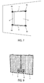
- FIG. 1 there is shown a particular embodiment of a closure device for an embrasure 4 of a building according to the invention, respectively in the closed position and in the open position.
- the closure device as shown comprises two flap shutter panels, or pivoting, 1, 2 for protecting and / or closing a window 3 positioned in a doorway 4 of a building.
- Each beating panel 1 (2) here comprises a solar photovoltaic panel, or module, composed of a photovoltaic solar cell assembly, mounted inside a support frame 11 (12).
- the photovoltaic module occupies all or almost all of the surface of the panel 1, 2, except the support frame 11 (12).
- “almost all” is meant to mean that a reduced number of photovoltaic cells can be replaced by an element such as a fan, as will be described later.
- the photovoltaic module is the flap panel 1 (2).
- the photovoltaic panels are bifacial, that is to say able to generate electricity from light rays incident on any of their front and rear faces. More specifically, the photovoltaic cells comprising the panels comprise two faces, front and rear, active (that is to say able to produce electricity from incident light radiation).
- the photovoltaic cells comprising the panels comprise two faces, front and rear, active (that is to say able to produce electricity from incident light radiation).
- it may be bifacial photovoltaic modules such as the modules "HIT ⁇ Double 195" of the company SANYO.
- the photovoltaic panels 1, 2 are here connected to a storage battery, intended to store the electrical energy produced by the panels.
- the photovoltaic panels could be connected to an electricity collection network.
- the closure device comprises a drive motor, not shown, shutter panels flap 1, 2.
- the swing panels 1, 2 are mounted as an exterior wall on the facade 5 of the building. They are movable between an open position as represented on the figure 3 , in which they are placed against a facade 5 of the building, and a closed position as shown on the figure 1 , in which they are placed in front of the embrasure 4 of the window 3.
- the closure device comprises four modules 6A to 6D of articulation of the two flap shutter panels 1, 2.
- the two modules 6A and 6B, respectively 6C and 6D, are intended to cooperate to move the panel 1, respectively of the panel 2, between two positions, open ( figure 3 ) and closed ( figure 1 ).
- Each articulation module 6A-6D is adapted so that the movement of the corresponding shutter panel between its two positions, open ( figure 3 ) and closed ( figure 1 ), comprises a pivoting component about a pivot 60, of vertical axis, and a translation component in a direction perpendicular to the axis of the pivot 60.
- the hinge 6C comprises a pivot axis 60, a drive shaft 64, a slideway 65, a first and a second link 61, 62 and a support portion 66-67.
- the slide, or slide, 65 is adapted to receive the pivot axis 60 and the drive shaft 64, as shown in FIG. Figure 2B .
- the pivot axis 60 and the drive shaft 64 are vertical.
- a horizontal return spring 68 is interposed between the pivot axis 60 and the drive shaft 64, the two ends of the spring 68 being respectively fixed to the two axes 60, 64.
- the slide 65 extends laterally in the extension of the upper part of the support frame 11 (12) of the flap panel flap 1 (2) and is integral therewith. More precisely, as can be seen from the figures 1 and 2B , the slideway 65 extends in the extension of the upper edge of the flap shutter panel 2.
- the slide of the articulation 6A extends in the extension of the upper edge of the panel 1
- the slides of the joints 6B and 6D extend in the extensions of the lower edges of the panels 1 and 2 respectively.
- the support portion is intended to be fixedly mounted in the recess 4. It comprises a plate 66 bearing against the facade 5, here having a global disc shape, and a support block 67, having a cube shape and intended to be placed in abutment against an inner corner of the embrasure 4.
- the pivot axis 60 is fixed to a horizontal base 69 secured to the support portion.
- the first link 61 comprises a first end fixedly mounted on the support portion 66-67 and a second end supporting an axis 63 for rotating the second link 62, connected to a motor axis.
- the second link 62 is pivotally mounted on the rod 61, by one of its ends which is integral with the drive shaft 63.
- the other end of the rod 62 is integral with the drive shaft 64.
- front and back here refer to the “front” and “back” edges of a panel which are respectively the farthest vertical edge and the vertical edge closest to the pivot axis. of the panel.
- the hinge 6C When the panel 2 is in the closed position, the hinge 6C is in the retracted position. In this position, the rod 62 is folded over the rod 61, and the drive shaft 64 is in abutment against the so-called "front" end of the slideway 65 (that is to say the connected one). to the support frame 12), and near the pivot axis 60, the spring 68 being compressed. The panel 2 is held in this position by any suitable locking means.
- the slideway 65 After unblocking of the panel 2, the slideway 65 is driven in forward and pivoting movement, under the action of return of the spring 68 and drive of the shaft 63, which is itself driven by the motor and in turn drives the link 62 in rotation. At first, the slideway 65 is driven forwardly by the return action of the spring 68. In a second step, the rear free end, of rounded shape, of the slideway 65 bears against the plate 66. (or against the facade 5) and plays a role of cam so as to continue the translational movement of the slide 65 by pivoting thereof.
- the movement of the slideway 65 thus comprises a forward translation component and a pivoting component about the pivot axis 60 in the opening direction.
- the slideway 65 being integral with the panel 2, it is driven similarly in forward movement while pivoting in the opening direction.
- the translational component of the movement is adapted to position the pivot axis 60 at the rear end of the slideway 65, as shown in the Figures 4 and 5 .
- the slideway 65 is driven in translation at first under the action With the forward translation component, the rear lateral overflow of the panel 2 is reduced so as to allow the panel 2 to rotate about 180 ° without being blocked by abutting its rear edge against the facade 5.
- the shutter panel When closing, the shutter panel is driven in a similar manner in a reverse movement to that just described, this movement comprising a rearward translation component and a pivot component in the closing direction around the pivot axis 60.
- the closing device also comprises here two telescopic arms, upper 7 and lower 8, having a dual function of fixing the device to the building and supporting the shutter panels flap 1, 2.
- Each arm 7 (8) comprises two cylindrical tubes, internal 70 and external 71, nested and screwed into one another and arranged to extend telescopically between a retracted position, in which the inner tube 70 (80) is housed almost completely in the outer tube 71 (81), and an extended position, wherein the inner tube 70 (80) extends substantially integrally out of the outer tube 71 (81).
- Each arm 7 (8) has at its two free ends two support pads (not shown) intended to bear against the internal walls facing each other, or jambs, of the embrasure 4.
- the tubes 70, 71 (80, 81) can be deployed or retracted for example by a rotational movement relative to each other. This rotation can be operated manually by a user.
- each arm 7 (8) in the recess 4 of the window 3 can be done in the following way: a user adjusts the size of the arm 7 (8) to that of the doorway. In a first step, it unfolds the arm 7 (8) by unscrewing so that the length of the arm is slightly less than the width of the embrasure 4. It then places the arm 7 (8) in the embrasure 4 at the top of the latter (respectively at the bottom), close to the facade, then continue unscrewing the arm 7 (8) until the end pads of the arm 7 (8) come into forced support against the internal side walls of the recess 4 and the arm 7 (8) is self-locked in the embrasure 4.
- the arms 7 and 8 are thus fixed to the inner walls or jambs of the recess 4, in a self-locking manner, by pressing against the jambs of the recess 4, in a manner similar to a shower rod.
- the hinge modules 6A to 6D are carried by the ends of the arms 7,8.
- the motor is housed in one of the arms 7 (8), for example the upper arm 7.
- the storage battery is also housed in the arm 7 and connected to the motor so as to power it electrically.
- the closure device is electrically autonomous and requires no connection to the mains.
- the closure device integrates one or more air circulation fans.
- each panel 1, 2 incorporates a fan 9, 10 positioned at the bottom of the panel.
- Each fan 9 (10) is mounted on a support frame 11 (12) of the corresponding photovoltaic panel 1 (2), for example at the bottom of the panel.
- the fans 9, 10 are powered electrically by the photovoltaic panels and / or the storage battery.
- the fans can be operated at night, when the shutter panels are closed, to bring fresh air inside.
- the device can integrate one or more lighting modules adapted to illuminate the exterior and / or interior of the building.
- the lighting can be used at night thanks to the electric energy accumulated during the day.
- One or more anti-intrusion sensors may also be provided in the closure device.
- the closure device comprises a module for optimizing the production of electricity, comprising a control unit, for example a microprocessor, and an optimization software program.
- This optimization module is adapted to control the position of the panels, and more precisely their opening angle, and thus optimally orient them in relation to the incident solar rays, according to time information including the date and time. , so as to maximize the production of electricity.
- a control unit for example a microprocessor
- This optimization module is adapted to control the position of the panels, and more precisely their opening angle, and thus optimally orient them in relation to the incident solar rays, according to time information including the date and time. , so as to maximize the production of electricity.
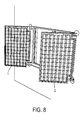
- ⁇ and (180- ⁇ there is shown on the figure 8 the two flap shutter panels 1, 2 oriented with respective opening angles ⁇ and (180- ⁇ ), the two panels being thus parallel to each other so as to both be oriented optimally with respect to the incident solar rays .
- the device may also include a sunshine detection module acting as a sunshine sensor.
- This module is adapted to play the role of a pyranometer and determine a level of sunshine, or solar radiation incident on the panels 1, 2 from measured data relating to the amount of electricity produced.
- the sun detection module can be coupled to a module for controlling the position of the panels 1, 2, arranged to control the position of the panels 1, 2 as a function of the level of sunshine detected and thus to regulate the penetration of the sunshine inside the building.
- the control module may for example control a total or at least partial closure of the panels 1,2 when the sun exceeds a predetermined threshold, during the summer, so as to reduce or completely eliminate the penetration of solar rays to the room. interior of the building. This limits the increase in temperature inside the building during the summer.
- the data relating to the production of electricity by the photovoltaic panels 1, 2 can be used to control the position of the panels 1, 2 and thus regulate the penetration of sunshine inside the building.
Landscapes
- Engineering & Computer Science (AREA)
- Mechanical Engineering (AREA)
- Operating, Guiding And Securing Of Roll- Type Closing Members (AREA)
- Specific Sealing Or Ventilating Devices For Doors And Windows (AREA)
Applications Claiming Priority (1)
| Application Number | Priority Date | Filing Date | Title |
|---|---|---|---|
| FR1363223A FR3015540B1 (fr) | 2013-12-20 | 2013-12-20 | Dispositif de fermeture pour une embrasure d'un batiment |
Publications (2)
| Publication Number | Publication Date |
|---|---|
| EP2886761A2 true EP2886761A2 (de) | 2015-06-24 |
| EP2886761A3 EP2886761A3 (de) | 2015-08-05 |
Family
ID=50489256
Family Applications (1)
| Application Number | Title | Priority Date | Filing Date |
|---|---|---|---|
| EP14199091.1A Withdrawn EP2886761A3 (de) | 2013-12-20 | 2014-12-19 | Verschlussvorrichtung für eine Öffnung in einem Gebäude |
Country Status (2)
| Country | Link |
|---|---|
| EP (1) | EP2886761A3 (de) |
| FR (1) | FR3015540B1 (de) |
Cited By (1)
| Publication number | Priority date | Publication date | Assignee | Title |
|---|---|---|---|---|
| US10505492B2 (en) | 2016-02-12 | 2019-12-10 | Solarcity Corporation | Building integrated photovoltaic roofing assemblies and associated systems and methods |
Families Citing this family (1)
| Publication number | Priority date | Publication date | Assignee | Title |
|---|---|---|---|---|
| CN110805314A (zh) * | 2019-11-01 | 2020-02-18 | 宿州学院 | 一种节能环保型建筑房屋 |
Family Cites Families (2)
| Publication number | Priority date | Publication date | Assignee | Title |
|---|---|---|---|---|
| DE29923628U1 (de) * | 1999-05-06 | 2000-12-14 | Steinbach & Vollmann GmbH & Co., 42579 Heiligenhaus | Scharnier |
| DE202004021716U1 (de) * | 2004-12-22 | 2010-09-09 | Iss Ag | Vorrichtung zum Schwenken drehbar gelagerter Flügelelemente |
-
2013
- 2013-12-20 FR FR1363223A patent/FR3015540B1/fr not_active Expired - Fee Related
-
2014
- 2014-12-19 EP EP14199091.1A patent/EP2886761A3/de not_active Withdrawn
Non-Patent Citations (1)
| Title |
|---|
| None |
Cited By (1)
| Publication number | Priority date | Publication date | Assignee | Title |
|---|---|---|---|---|
| US10505492B2 (en) | 2016-02-12 | 2019-12-10 | Solarcity Corporation | Building integrated photovoltaic roofing assemblies and associated systems and methods |
Also Published As
| Publication number | Publication date |
|---|---|
| FR3015540A1 (fr) | 2015-06-26 |
| EP2886761A3 (de) | 2015-08-05 |
| FR3015540B1 (fr) | 2018-01-19 |
Similar Documents
| Publication | Publication Date | Title |
|---|---|---|
| EP3803021B1 (de) | Rollladenvorrichtung für eine heimautomatisierungs- oder sonnenschutzvorrichtung in einem gebäude und zugehörige heimautomatisierungsinstallation | |
| EP3528310B1 (de) | Speichervorrichtung für elektrische energie, entsprechende motorisierte antriebsvorrichtung und entsprechende haustechnikanlage | |
| FR2966494A1 (fr) | Volet roulant pour ouvrant de batiment | |
| EP2886761A2 (de) | Verschlussvorrichtung für eine Öffnung in einem Gebäude | |
| FR2972754A1 (fr) | Installation de fermeture ou de protection solaire, et procede de mise en oeuvre d'une telle installation | |
| EP3216963B1 (de) | Dreh-kippfenster für ein gebäude, und hausanlage, die ein solches dreh-kippfenster umfasst | |
| EP3190256A1 (de) | Haustechnikanlage und entsprechendes steuerungsverfahren | |
| EP3190253B1 (de) | Dreh-kippfenster für ein gebäude, und hausanlage, die ein solches dreh-kippfenster umfasst | |
| EP4174276B9 (de) | Elektromechanischer aktuator, verdunkelungsvorrichtung mit solch einem aktuator und verfahren zur steuerung solch eines aktuators | |
| FR2957113A1 (fr) | Bloc volet battant motorise | |
| FR3053070B1 (fr) | Fenetre pour un batiment et installation domotique comprenant une telle fenetre | |
| WO2012080386A9 (fr) | Mecanisme de rotation des lames d'un volet roulant | |
| FR2941005A1 (fr) | Systeme de type volet persienne | |
| EP3584386A2 (de) | Beschattungsvorrichtung, die geeignet ist, mindestens teilweise eine wandöffnung und einen eine solche vorrichtung umfassenden fensterblock abzudecken | |
| FR3092607A1 (fr) | Installation pour un bâtiment comprenant un dispositif d’occultation, une fenêtre et un dispositif de ventilation | |
| EP3263822B1 (de) | Haustechnikanlage | |
| EP3173564B1 (de) | Rahmen für klappladen | |
| FR3104185A1 (fr) | Volet coulissant à projection multifonctionnel | |
| EP3461986A1 (de) | Rollladen mit verstellbaren lamellen | |
| EP1146199B1 (de) | Rolladen mit Infrarotdetektor | |
| EP2183444A2 (de) | Einzelkonsolenmarkise | |
| EP4086423A1 (de) | Motorisierte antriebsvorrichtung für eine verdunkelungsvorrichtung und entsprechende verdunkelungsvorrichtung | |
| EP4704501A1 (de) | Stromversorgungsvorrichtung, motorantriebsvorrichtung mit einer solchen stromversorgungsvorrichtung und verdunkelungsvorrichtung dafür | |
| FR3166920A1 (fr) | Volet à lames orientables motorisé | |
| FR3147314A1 (fr) | Dispositif d’occultation |
Legal Events
| Date | Code | Title | Description |
|---|---|---|---|
| PUAI | Public reference made under article 153(3) epc to a published international application that has entered the european phase |
Free format text: ORIGINAL CODE: 0009012 |
|
| 17P | Request for examination filed |
Effective date: 20141219 |
|
| AK | Designated contracting states |
Kind code of ref document: A2 Designated state(s): AL AT BE BG CH CY CZ DE DK EE ES FI FR GB GR HR HU IE IS IT LI LT LU LV MC MK MT NL NO PL PT RO RS SE SI SK SM TR |
|
| AX | Request for extension of the european patent |
Extension state: BA ME |
|
| PUAL | Search report despatched |
Free format text: ORIGINAL CODE: 0009013 |
|
| AK | Designated contracting states |
Kind code of ref document: A3 Designated state(s): AL AT BE BG CH CY CZ DE DK EE ES FI FR GB GR HR HU IE IS IT LI LT LU LV MC MK MT NL NO PL PT RO RS SE SI SK SM TR |
|
| AX | Request for extension of the european patent |
Extension state: BA ME |
|
| RIC1 | Information provided on ipc code assigned before grant |
Ipc: E05D 3/02 20060101AFI20150626BHEP |
|
| R17P | Request for examination filed (corrected) |
Effective date: 20160204 |
|
| RBV | Designated contracting states (corrected) |
Designated state(s): AL AT BE BG CH CY CZ DE DK EE ES FI FR GB GR HR HU IE IS IT LI LT LU LV MC MK MT NL NO PL PT RO RS SE SI SK SM TR |
|
| STAA | Information on the status of an ep patent application or granted ep patent |
Free format text: STATUS: EXAMINATION IS IN PROGRESS |
|
| 17Q | First examination report despatched |
Effective date: 20180622 |
|
| STAA | Information on the status of an ep patent application or granted ep patent |
Free format text: STATUS: THE APPLICATION IS DEEMED TO BE WITHDRAWN |
|
| 18D | Application deemed to be withdrawn |
Effective date: 20200701 |