EP2886876A1 - Gabelstapler, Hydraulikzylinderanordnung und Hydraulikvorrichtung dafür - Google Patents
Gabelstapler, Hydraulikzylinderanordnung und Hydraulikvorrichtung dafür Download PDFInfo
- Publication number
- EP2886876A1 EP2886876A1 EP14195197.0A EP14195197A EP2886876A1 EP 2886876 A1 EP2886876 A1 EP 2886876A1 EP 14195197 A EP14195197 A EP 14195197A EP 2886876 A1 EP2886876 A1 EP 2886876A1
- Authority
- EP
- European Patent Office
- Prior art keywords
- oil
- cylinder
- piston
- hydraulic
- liner
- Prior art date
- Legal status (The legal status is an assumption and is not a legal conclusion. Google has not performed a legal analysis and makes no representation as to the accuracy of the status listed.)
- Granted
Links
Images



Classifications
-
- F—MECHANICAL ENGINEERING; LIGHTING; HEATING; WEAPONS; BLASTING
- F15—FLUID-PRESSURE ACTUATORS; HYDRAULICS OR PNEUMATICS IN GENERAL
- F15B—SYSTEMS ACTING BY MEANS OF FLUIDS IN GENERAL; FLUID-PRESSURE ACTUATORS, e.g. SERVOMOTORS; DETAILS OF FLUID-PRESSURE SYSTEMS, NOT OTHERWISE PROVIDED FOR
- F15B15/00—Fluid-actuated devices for displacing a member from one position to another; Gearing associated therewith
- F15B15/08—Characterised by the construction of the motor unit
- F15B15/14—Characterised by the construction of the motor unit of the straight-cylinder type
- F15B15/149—Fluid interconnections, e.g. fluid connectors, passages
-
- F—MECHANICAL ENGINEERING; LIGHTING; HEATING; WEAPONS; BLASTING
- F15—FLUID-PRESSURE ACTUATORS; HYDRAULICS OR PNEUMATICS IN GENERAL
- F15B—SYSTEMS ACTING BY MEANS OF FLUIDS IN GENERAL; FLUID-PRESSURE ACTUATORS, e.g. SERVOMOTORS; DETAILS OF FLUID-PRESSURE SYSTEMS, NOT OTHERWISE PROVIDED FOR
- F15B15/00—Fluid-actuated devices for displacing a member from one position to another; Gearing associated therewith
- F15B15/08—Characterised by the construction of the motor unit
- F15B15/14—Characterised by the construction of the motor unit of the straight-cylinder type
- F15B15/1423—Component parts; Constructional details
- F15B15/1428—Cylinders
-
- B—PERFORMING OPERATIONS; TRANSPORTING
- B66—HOISTING; LIFTING; HAULING
- B66F—HOISTING, LIFTING, HAULING OR PUSHING, NOT OTHERWISE PROVIDED FOR, e.g. DEVICES WHICH APPLY A LIFTING OR PUSHING FORCE DIRECTLY TO THE SURFACE OF A LOAD
- B66F9/00—Devices for lifting or lowering bulky or heavy goods for loading or unloading purposes
- B66F9/06—Devices for lifting or lowering bulky or heavy goods for loading or unloading purposes movable, with their loads, on wheels or the like, e.g. fork-lift trucks
- B66F9/075—Constructional features or details
- B66F9/20—Means for actuating or controlling masts, platforms, or forks
- B66F9/22—Hydraulic devices or systems
-
- F—MECHANICAL ENGINEERING; LIGHTING; HEATING; WEAPONS; BLASTING
- F15—FLUID-PRESSURE ACTUATORS; HYDRAULICS OR PNEUMATICS IN GENERAL
- F15B—SYSTEMS ACTING BY MEANS OF FLUIDS IN GENERAL; FLUID-PRESSURE ACTUATORS, e.g. SERVOMOTORS; DETAILS OF FLUID-PRESSURE SYSTEMS, NOT OTHERWISE PROVIDED FOR
- F15B11/00—Servomotor systems without provision for follow-up action; Circuits therefor
- F15B11/08—Servomotor systems without provision for follow-up action; Circuits therefor with only one servomotor
-
- F—MECHANICAL ENGINEERING; LIGHTING; HEATING; WEAPONS; BLASTING
- F15—FLUID-PRESSURE ACTUATORS; HYDRAULICS OR PNEUMATICS IN GENERAL
- F15B—SYSTEMS ACTING BY MEANS OF FLUIDS IN GENERAL; FLUID-PRESSURE ACTUATORS, e.g. SERVOMOTORS; DETAILS OF FLUID-PRESSURE SYSTEMS, NOT OTHERWISE PROVIDED FOR
- F15B11/00—Servomotor systems without provision for follow-up action; Circuits therefor
- F15B11/08—Servomotor systems without provision for follow-up action; Circuits therefor with only one servomotor
- F15B11/15—Servomotor systems without provision for follow-up action; Circuits therefor with only one servomotor with special provision for automatic return
-
- F—MECHANICAL ENGINEERING; LIGHTING; HEATING; WEAPONS; BLASTING
- F15—FLUID-PRESSURE ACTUATORS; HYDRAULICS OR PNEUMATICS IN GENERAL
- F15B—SYSTEMS ACTING BY MEANS OF FLUIDS IN GENERAL; FLUID-PRESSURE ACTUATORS, e.g. SERVOMOTORS; DETAILS OF FLUID-PRESSURE SYSTEMS, NOT OTHERWISE PROVIDED FOR
- F15B2211/00—Circuits for servomotor systems
- F15B2211/70—Output members, e.g. hydraulic motors or cylinders or control therefor
- F15B2211/77—Control of direction of movement of the output member
- F15B2211/7725—Control of direction of movement of the output member with automatic reciprocation
-
- F—MECHANICAL ENGINEERING; LIGHTING; HEATING; WEAPONS; BLASTING
- F15—FLUID-PRESSURE ACTUATORS; HYDRAULICS OR PNEUMATICS IN GENERAL
- F15B—SYSTEMS ACTING BY MEANS OF FLUIDS IN GENERAL; FLUID-PRESSURE ACTUATORS, e.g. SERVOMOTORS; DETAILS OF FLUID-PRESSURE SYSTEMS, NOT OTHERWISE PROVIDED FOR
- F15B2215/00—Fluid-actuated devices for displacing a member from one position to another
- F15B2215/30—Constructional details thereof
Definitions
- Embodiments of the present disclosure generally relate to a forklift, a hydraulic cylinder assembly and a hydraulic device thereof.
- a straight line reciprocating motion mechanism is wildly used in a modern mechanical field, such as a feeding mechanism of an automatic cutting machine and an automatic feeding mechanism, etc.
- the straight line reciprocating motion mechanism with a mechanical transmission is unavoidably subjected to a large inertial impact when a motion direction is changed, which reduces a service life of the straight line reciprocating motion mechanism and generates ambient noise.
- Embodiments of the present disclosure seek to solve at least one of the problems existing in the related art to at least some extent.
- a first object of the present disclosure is to provide a hydraulic cylinder assembly for providing a straight line reciprocating motion, with a lower noise and a longer service life.
- a second object of the present disclosure is to provide a hydraulic device having the hydraulic cylinder assembly.
- a third object of the present disclosure is to provide a forklift having the hydraulic cylinder assembly.
- Embodiments of a first aspect of the present disclosure provide a hydraulic cylinder assembly, which includes a cylinder defining a first oil inlet, a second oil inlet, a first oil outlet and a second oil outlet therein; a cylinder liner disposed within the cylinder and being moveable between a first position and a second position, and defining a first oil port and a second oil port therein; a piston disposed within the cylinder liner and being moveable between a third position and a fourth position; and a piston rod connected with at least one of two end faces of the piston and defining a free end extended out of the cylinder, wherein a first oil chamber and a second oil chamber are defined by the cylinder, the cylinder liner and the piston and located at two sides of the piston respectively, the first oil chamber is normally communicated with the first oil port, and the second oil chamber is normally communicated with the second oil port, wherein when the cylinder liner is located at the first position, a communication between the first oil inlet and the first oil port
- a sliding resistance between the piston and the cylinder liner is less than that between the cylinder liner and the cylinder.
- a first oil groove and a second oil groove are formed in the cylinder liner, the first oil groove is normally communicated with the first oil port and the first oil chamber respectively, and the second oil groove is normally communicated with the second oil port and the second oil chamber respectively.
- the hydraulic cylinder assembly further includes a first seal ring, wherein a liner groove is formed in an outer peripheral surface of the cylinder liner and configured to receive the first seal ring therein.
- a plurality of the liner grooves are provided and spaced apart from one another in a length direction of the cylinder liner, a plurality of the first seal rings are provided and fitted into the liner grooves in a manner of one-to-one correspondence.
- the hydraulic cylinder assembly further includes a second seal ring, wherein a piston groove is formed in an outer peripheral surface of the piston and configured to receive the second seal ring therein.
- the cylinder includes: a cylinder body; a first guide member and a second guide member disposed at two ends of the cylinder body respectively, wherein the free end of each piston rod is extended out of the cylinder through a corresponding one of the first and second guide members.
- the cylinder further includes a first end cover and a second end cover disposed at the two ends of the cylinder body and covering the first and second guide members respectively.
- the hydraulic cylinder assembly further includes a third seal ring, wherein a cover groove is formed in each of the first and second end covers, wherein the third seal ring is disposed in the cover groove and fitted over an outer peripheral surface of the piston rod.
- Embodiments of a second aspect of the present disclosure provide a hydraulic device.
- the hydraulic device includes: the hydraulic cylinder assembly according to embodiments of the first aspect of the present disclosure and an oil pump communicated with the first oil inlet and the second oil inlet to supply hydraulic oil to the first and second oil inlets respectively.
- one oil pump is provided.
- the oil pump comprises a first sub-oil pump communicated with the first oil inlet to supply hydraulic oil to the first oil inlet and a second sub-oil pump communicated with the second oil inlet to supply hydraulic oil to the second oil inlet.
- Embodiments of a third aspect of the present disclosure provide a forklift.
- the forklift includes the hydraulic device according to embodiments of the second aspect of the present disclosure.
- relative terms such as “central”, “longitudinal”, “lateral”, “front”, “rear”, “right”, “left”, “inner”, “outer”, “lower”, “upper”, “horizontal”, “vertical”, “above”, “below”, “up”, “top”, “bottom”, “inner”, “outer”, “clockwise”, “anticlockwise” as well as derivative thereof (e.g., “horizontally”, “downwardly”, “upwardly”, etc.) should be construed to refer to the orientation as then described or as shown in the drawings under discussion. These relative terms are for convenience of description and do not require that the present disclosure be constructed or operated in a particular orientation.
- terms such as “first” and “second” are used herein for purposes of description and are not intended to indicate or imply relative importance or significance.
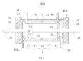
- a hydraulic cylinder assembly 100 is adapted to provide a straight line reciprocating motion for mechanical and hydraulic transmissions.
- the hydraulic cylinder assembly 100 includes a cylinder 1, a cylinder liner 2 and a piston 31.
- the cylinder 1 has a first oil inlet 151, a second oil inlet 152, a first oil outlet 153 and a second oil outlet 154 therein.
- a section of the cylinder 1 in a length direction, i.e. an axial direction, of the cylinder 1 may be configured as a rectangle, and the first and second oil inlets 151, 152 may be formed at one side, such as an upper side in the drawings of the cylinder 1, the first and second oil outlets 153, 154 may be formed at the other side, such as a lower side in the drawings of the cylinder 1.
- An interior of the cylinder 1 is hollow and communicated with the first oil inlet 151, the second oil inlet 152, the first oil outlet 153 and the second oil outlet 154 respectively.
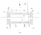
- the cylinder liner 2 is disposed within the cylinder 1 and moveable between a first position and a second position, in other words, within the cylinder 1, the cylinder liner 2 can be moved between the first and second positions relative to the cylinder 1. As shown in Figs. 1-3 , the cylinder liner 2 is located at the first position relative to the cylinder 1; correspondingly, as shown in Figs. 4-5 , the cylinder liner 2 is located at the second position relative to the cylinder 1.
- the cylinder liner 1 has a first oil port 21 and a second oil port 22 therein.
- a section of the cylinder liner 2 in the length direction of the cylinder 1 may be configured as a rectangle as well.
- An interior of the cylinder liner 2 is hollow and communicated with the first and second oil ports 21, 22 respectively.
- a seal structure may be formed between an outer wall of the cylinder liner 2 and an inner wall of the cylinder 1 after an assembling of the cylinder liner 2 and cylinder 1 being finished, or a first seal ring 51, which will be described hereinafter, may be configured as a seal structure between the cylinder liner 2 and cylinder 1.
- the piston 31 is disposed within the cylinder liner 1 and moveable between a third position and a fourth position, in other words, within the cylinder liner 2, the piston 31 can be moved between the third and fourth positions relative to the cylinder liner 2.
- the piston 31 is located at the third position relative to the cylinder liner 2; correspondingly, as shown in Fig. 3 and Fig. 4 , the piston 31 is located at the fourth position relative to the cylinder liner 2.
- a first oil chamber 41 and a second oil chamber 42 are defined by the cylinder 1, the cylinder liner 2 and the piston 31 and located at two sides of the piston 31 respectively, i.e. the first oil chamber 41 is located at a left side of the piston 31 as shown in the drawings, the second oil chamber 42 is located at a right side of the piston 31 as shown in the drawings.
- volumes of the first and second oil chambers 41, 42 are variable. For example, the volume of the first oil chamber 41 is increased and the volume of the second oil chamber 42 is reduced gradually during the motion of the piston 31 from the third position to the fourth position. Similarly, the volume of the first oil chamber 41 is reduced and the volume of the second oil chamber 42 is increased gradually during the motion of the piston 31 from the fourth position to the third position.
- the first oil chamber 41 is normally communicated with the first oil port 21, and the second oil chamber 42 is normally communicated with the second oil port 22.
- the first oil chamber 41 can be always communicated with the first oil port 21, and the second oil chamber 42 can be always communicated with the second oil port 22 regardless of the motion of the piston 31 relative to the cylinder liner 2 and the motion of the cylinder liner 2 relative to the cylinder 1.
- a piston rod 32 is connected with at least one of two end faces of the piston 31 and has a free end extended out of the cylinder 1.
- two piston rods 32 are connected with the two end faces of the piston 31 respectively.
- the piston 31 and the piston rod 32 may be formed integrally or may be separate components.
- the piston 31 and the piston rod 32 may be connected together by different connection means, such as bolts, if the piston 31 and the piston rod 32 are separate components.
- a communication between the first oil inlet 151 and the first oil port 21 is formed, i.e. the first oil inlet 151 is communicated with the first oil port 21, a communication between the second oil inlet 152 and the second oil port 22 is interrupted, i.e. the second oil inlet 152 is not communicated with the second oil port 22, a communication between the first oil chamber 41 and the first oil outlet 153 is interrupted, and a communication between the second oil chamber 42 and the second oil outlet 154 is formed.
- an oil pump 200 supplies the first and second oil inlets 151, 152 with hydraulic oil continuously, the hydraulic oil flows into the first oil chamber 41 via the first oil inlet 151 and the first oil port 21 in turn, since the second oil inlet 152 is not communicated with the second oil port 22. Because an oil pressure inside the first oil chamber 41 is increased and the first oil chamber 41 is not communicated with the first oil outlet 153, the piston 31 is driven to move from the third position to the fourth position. During this motion of the piston 31, the second oil chamber 42 is compressed, so that the hydraulic oil within the second oil chamber 42 flows back to a hydraulic oil tank via the second oil outlet 154.
- the oil pump 200 supplies the first and second oil inlets 151, 152 with hydraulic oil continuously, the hydraulic oil flows into the second oil chamber 42 via the second oil inlet 152 and the second oil port 22 in turn, since the first oil inlet 151 is not communicated with the first oil port 21. Because an oil pressure inside the second oil chamber 42 is increased and the second oil chamber 42 is not communicated with the second oil outlet 154, the piston 31 is driven to move from the fourth position to the third position. During this motion of the piston 31, the first oil chamber 41 is compressed, so that the hydraulic oil within the first oil chamber 41 flows back to a hydraulic oil tank via the first oil outlet 153.
- the piston 31 With the continuous supply of hydraulic oil to the first and second oil inlets 151, 152 by the oil pump 200, the piston 31 can be moved in a manner of the straight line reciprocating motion, and thus the moving parts can be moved in the manner of the straight line reciprocating motion along with the motion of the piston 31 when the free ends of the piston rods 32 are connected with the moving parts.
- the communication between the first oil inlet 151 and the first oil port 21 is fully interrupted. In other words, during the above described motion, the state of the first oil inlet 151 and the first oil port 21 is transited from communication to interruption gradually.
- the state of the second oil inlet 152 and the second oil port 22 is transited from interruption to communication gradually.
- the first oil inlet 151 is communicated with the first oil port 21
- the second oil inlet 152 is communicated with the second oil port 22, i.e. the hydraulic oil can be fed into the cylinder liner 2 via both of the first and second oil inlets 151 and 152.
- the piston 31 can still drive the cylinder liner 2 to move from the first position to the second position due to moving inertia of the piston 31 and the cylinder liner 2.
- a resistance force is generated to reduce a moving speed of the cylinder liner 2 and buffer an impact between the cylinder liner 2 and the cylinder 1 due to formations of both communications between the first oil inlet 151 and the first oil port 21 and between the second oil inlet 152 and the second oil port 22.
- a rigid impact between the cylinder liner 2 and the cylinder 1 can be avoided, a service life of the hydraulic cylinder assembly 100 can be increased, and a working noise of the hydraulic cylinder assembly 100 can be reduced.
- the interruption between a certain inlet and a certain port means that the inlet and the port may be staggered in the relative motion between the cylinder 1 and cylinder liner 2, so that the inlet is not communicated with the port temporarily.
- the interruption between the second oil inlet 152 and the second oil port 22 means that the communication of the second oil inlet 152 and the second oil port 22 is interrupted temporarily, so that the hydraulic oil cannot be fed to the second oil port 22 via the second oil inlet 152.
- the hydraulic cylinder assembly 100 since the piston rod 32 is connected with a moving part to drive the moving part to move in a manner of the straight line reciprocating motion, when the hydraulic cylinder assembly 100 changes the moving direction of the moving part, an inertial impact of the cylinder liner 2 against the cylinder 1 can be reduced greatly, thus prolonging the service life of the hydraulic cylinder assembly 100 and reducing the working noise of the hydraulic cylinder assembly 100.
- a sliding resistance between the piston 31 and the cylinder liner 2 is less than that between the cylinder liner 2 and the cylinder 1.
- a first oil groove 23 and a second oil groove 24 are formed in the cylinder liner 2, the first oil groove 23 is normally communicated with the first oil port 21 and the first oil chamber 41 respectively, and the second oil groove 24 is normally communicated with the second oil port 22 and the second oil chamber 42 respectively.
- hydraulic oil may flow into the first oil chamber 41 via the first oil port 21 and into the second oil chamber 42 via the second oil port 22 easily.
- a liner groove is formed in an outer peripheral surface of the cylinder liner 2.
- the hydraulic cylinder assembly 100 further includes a first seal ring 51 which is configured to be fitted into the liner groove, so that a seal between the outer peripheral surface of the cylinder liner 2 and an inner peripheral surface of the cylinder 1 is formed by the first seal ring 51 to prevent the hydraulic oil from flowing.
- a plurality of the liner grooves are provided and spaced apart from one another in a length direction of the cylinder liner 2 (i.e. a left-right direction as shown in Figs. 1-5 ), a plurality of the first seal rings 51 are also provided and fitted into the liner grooves in a manner of one-to-one correspondence.
- a plurality of seals are formed between the outer peripheral surface of the cylinder liner 2 and the inner peripheral surface of the cylinder 1, so that the seal effect can be improved greatly.
- the liner groove may be configured as a ring groove and formed integrally with the outer peripheral surface of the cylinder liner 2.
- the first seal ring 51 may be made of rubber, but not limited to this.
- a piston groove is formed in an outer peripheral surface of the piston 31.
- the hydraulic cylinder assembly 100 may further include a second seal ring 52 which is configured to be fitted into the piston groove, so that a seal between the outer peripheral surface of the piston 31 and an inner peripheral surface of the cylinder liner 2 is formed by the second seal ring 52 to prevent the hydraulic oil from flowing between the first oil chamber 41 and the second oil chamber 42.
- a plurality of the piston grooves are provided and spaced apart from one another in the length direction of the cylinder liner 2, a plurality of the second seal rings 52 are also provided and fitted into the piston grooves in a manner of one-to-one correspondence.
- a plurality of seals are formed between the outer peripheral surface of the piston 31 and the inner peripheral surface of the cylinder liner 2, so that the seal effect can be improved greatly.
- the piston groove may be configured as a ring groove and formed integrally with the outer peripheral surface of the piston 31.
- the second seal ring 52 may be made of rubber, but not limited to this.
- the cylinder 1 includes a cylinder body 15, a first guide member 11, a second guide member 12, a first end cover 13 and a second end cover 14.
- first and second end covers 13, 14 are disposed at two ends of the cylinder body 15 respectively, the free end of each piston rod 32 is extended out of the cylinder 1 through a corresponding one of the first and second guide members 13, 14.
- a free end of a left piston rod 32 is extended leftwards and penetrates the first guide member 11, the first guide member 11 guides a motion direction of the left piston rod 32 merely to ensure a straight line reciprocating motion in the axial direction of the left piston rod 32.
- a free end of a right piston rod 32 is extended rightwards and penetrates the second guide member 12, the second guide member 12 guides a motion direction of the right piston rod 32 merely to ensure a straight line reciprocating motion along the axial direction of the right piston rod 32.
- the first end cover 13 and the second end cover 14 are disposed at the two ends of the cylinder body 15 and cover the first and second guide members 11 and 12 respectively. Specifically, the first end cover 13 may be disposed a left end of the cylinder body 15 and covers the first guide member 11, and the second end cover 14 may be disposed a right end of the cylinder body 15 and covers the second guide member 12. Thus, dust and impurities are prevented from entering into the cylinder 1 via the first and second guide members 11 and 12.
- a cover groove is formed in each of the first and second end covers 13 and 14, and the hydraulic cylinder assembly 100 further includes a third seal ring 53 which is disposed in the cover groove and fitted over an outer peripheral surface of each piston rod 32.
- each of the end covers 13 and 14 may have a plurality of the cover grooves, and a plurality of the third seal rings 53 are also provided to form a plurality of seals with the cover grooves.
- the third seal ring 53 may be made of rubber, but not limited to this.
- the hydraulic device includes a hydraulic cylinder assembly 100 and an oil pump 200.
- the hydraulic cylinder assembly 100 is described in the above mentioned embodiments.
- the oil pump 200 is communicated with the first oil inlet 151 and the second oil inlet 152 to supply hydraulic oil to the first and second oil inlets 151 and 152 respectively.
- only one oil pump 200 is provided, but not limited to this, so that the hydraulic device according to embodiments of the present disclosure has a simple structure.
- the oil pump 200 may include a first sub-oil pump and a second sub-oil pump (not shown), the first sub-oil pump is communicated with the first oil inlet 151 to supply hydraulic oil to the first oil inlet 151 and the second sub-oil pump is communicated with the second oil inlet 152 to supply hydraulic oil to the second oil inlet 152.
- the forklift according to embodiments of the present disclosure includes a hydraulic device which is described in the above mentioned embodiments. It can be understood that the other structures and working principle of the forklift according to embodiments of the present disclosure are known to those skilled in the related art, so that the relative descriptions will be omitted herein.
Landscapes
- Engineering & Computer Science (AREA)
- Mechanical Engineering (AREA)
- Physics & Mathematics (AREA)
- Fluid Mechanics (AREA)
- General Engineering & Computer Science (AREA)
- Structural Engineering (AREA)
- Transportation (AREA)
- Combustion & Propulsion (AREA)
- Civil Engineering (AREA)
- Chemical & Material Sciences (AREA)
- Life Sciences & Earth Sciences (AREA)
- Geology (AREA)
- Actuator (AREA)
- Forklifts And Lifting Vehicles (AREA)
Applications Claiming Priority (1)
| Application Number | Priority Date | Filing Date | Title |
|---|---|---|---|
| CN201310629274.2A CN104675789B (zh) | 2013-11-29 | 2013-11-29 | 液压油缸、液压装置及叉车 |
Publications (2)
| Publication Number | Publication Date |
|---|---|
| EP2886876A1 true EP2886876A1 (de) | 2015-06-24 |
| EP2886876B1 EP2886876B1 (de) | 2018-10-24 |
Family
ID=52002754
Family Applications (1)
| Application Number | Title | Priority Date | Filing Date |
|---|---|---|---|
| EP14195197.0A Active EP2886876B1 (de) | 2013-11-29 | 2014-11-27 | Gabelstapler, Hydraulikzylinderanordnung und Hydraulikvorrichtung dafür |
Country Status (5)
| Country | Link |
|---|---|
| US (1) | US10253790B2 (de) |
| EP (1) | EP2886876B1 (de) |
| JP (1) | JP6234578B2 (de) |
| CN (1) | CN104675789B (de) |
| WO (1) | WO2015078360A1 (de) |
Families Citing this family (14)
| Publication number | Priority date | Publication date | Assignee | Title |
|---|---|---|---|---|
| CN108050127A (zh) * | 2017-12-27 | 2018-05-18 | 宣城铁凝机械有限公司 | 一种高密封度的气压缸 |
| CN108557713A (zh) * | 2018-06-29 | 2018-09-21 | 衡阳合力工业车辆有限公司 | 一种液压站及叉车 |
| CN109443819B (zh) * | 2018-12-13 | 2023-09-12 | 常州纺织服装职业技术学院 | 一种冲压机床加载装置 |
| KR102092481B1 (ko) * | 2018-12-19 | 2020-04-20 | 주식회사 두산 | 건설장비용 선회모터의 반전방지 밸브 |
| KR102781339B1 (ko) * | 2019-03-06 | 2025-03-17 | 신경순 | 공압 실린더 시스템 및 이를 포함하는 차단 밸브 |
| CN110595743B (zh) * | 2019-07-31 | 2021-11-16 | 武汉船用机械有限责任公司 | 用于轴式配油器的调距试验工装 |
| CN111207130B (zh) * | 2020-02-04 | 2022-11-18 | 龙岩市山力工程液压有限公司 | 一种油缸 |
| US20220243708A1 (en) * | 2021-01-29 | 2022-08-04 | Forum Us, Inc. | Pump system |
| CN113124016B (zh) * | 2021-04-19 | 2022-09-20 | 东北石油大学 | 一种自动往复液压缸 |
| CN114046285A (zh) * | 2021-10-14 | 2022-02-15 | 武汉船用机械有限责任公司 | 液压油缸 |
| CN114754042B (zh) * | 2022-04-15 | 2025-11-04 | 宁波悦威液压科技有限公司 | 一种具有防锈缸套的模块化单作用油缸 |
| CN115157952B (zh) * | 2022-08-31 | 2025-09-02 | 徐州徐工矿业机械有限公司 | 悬挂油缸液控系统、自适应油气悬架系统以及悬挂油缸平衡位置的调节方法 |
| CN115949566B (zh) * | 2023-01-09 | 2025-05-20 | 大连理工大学 | 针对超高压强流体条件下的节能高压液压泵装置及使用方法 |
| CN116237722A (zh) * | 2023-04-28 | 2023-06-09 | 杭州富阳诺德液压技术有限公司 | 一种液压缸缸体加工工艺 |
Citations (3)
| Publication number | Priority date | Publication date | Assignee | Title |
|---|---|---|---|---|
| GB771269A (en) * | 1955-07-11 | 1957-03-27 | Pathon Mfg Company | Hydraulic operator |
| US3301196A (en) * | 1964-01-30 | 1967-01-31 | Glas Maurus | Piston machine |
| DE10108257A1 (de) * | 2001-02-21 | 2002-09-12 | Uwe Hecker | Hydraulikzylinder |
Family Cites Families (12)
| Publication number | Priority date | Publication date | Assignee | Title |
|---|---|---|---|---|
| US827107A (en) * | 1905-12-06 | 1906-07-31 | Elonzo Able Maynard | Engine. |
| US1056736A (en) * | 1911-11-20 | 1913-03-18 | William L Carey | Slide-valve engine. |
| US1418079A (en) * | 1921-07-23 | 1922-05-30 | Harry H Diamond | Steam cylinder |
| JPS59144806A (ja) * | 1983-02-04 | 1984-08-20 | Nippon Air Brake Co Ltd | 油圧シリンダのクツシヨン装置 |
| US5577433A (en) * | 1995-09-06 | 1996-11-26 | Henry; Michael F. | Regulated speed linear actuator |
| CN2270839Y (zh) * | 1996-07-30 | 1997-12-17 | 吴平 | 代自增压环的加压装置 |
| JPH10169613A (ja) * | 1996-12-10 | 1998-06-23 | Fuji Electric Co Ltd | 油圧シリンダおよびその操作方法 |
| CN2331651Y (zh) * | 1998-05-07 | 1999-08-04 | 杨鹏波 | 新型叉车货叉专用调距装置 |
| JP2001090704A (ja) * | 1999-09-21 | 2001-04-03 | Tokimec Inc | 駆動装置 |
| GB0501893D0 (en) * | 2005-01-29 | 2005-03-09 | Goodrich Actuation Systems Ltd | Linear hydraulic actuator |
| CN202031908U (zh) * | 2011-03-22 | 2011-11-09 | 泸州市巨力液压有限公司 | 快进式油缸 |
| CN202326505U (zh) * | 2011-11-28 | 2012-07-11 | 安庆市天润工程机械有限责任公司 | 一种叉车转向液压缸 |
-
2013
- 2013-11-29 CN CN201310629274.2A patent/CN104675789B/zh active Active
-
2014
- 2014-11-25 WO PCT/CN2014/092201 patent/WO2015078360A1/en not_active Ceased
- 2014-11-25 JP JP2016534956A patent/JP6234578B2/ja active Active
- 2014-11-27 EP EP14195197.0A patent/EP2886876B1/de active Active
-
2016
- 2016-05-04 US US15/146,691 patent/US10253790B2/en active Active
Patent Citations (3)
| Publication number | Priority date | Publication date | Assignee | Title |
|---|---|---|---|---|
| GB771269A (en) * | 1955-07-11 | 1957-03-27 | Pathon Mfg Company | Hydraulic operator |
| US3301196A (en) * | 1964-01-30 | 1967-01-31 | Glas Maurus | Piston machine |
| DE10108257A1 (de) * | 2001-02-21 | 2002-09-12 | Uwe Hecker | Hydraulikzylinder |
Also Published As
| Publication number | Publication date |
|---|---|
| JP6234578B2 (ja) | 2017-11-22 |
| US10253790B2 (en) | 2019-04-09 |
| WO2015078360A1 (en) | 2015-06-04 |
| CN104675789B (zh) | 2017-04-12 |
| US20160245313A1 (en) | 2016-08-25 |
| CN104675789A (zh) | 2015-06-03 |
| EP2886876B1 (de) | 2018-10-24 |
| JP2016540165A (ja) | 2016-12-22 |
Similar Documents
| Publication | Publication Date | Title |
|---|---|---|
| EP2886876B1 (de) | Gabelstapler, Hydraulikzylinderanordnung und Hydraulikvorrichtung dafür | |
| KR102273877B1 (ko) | 주행 모터 전환 밸브, 주행 모터 및 토목 기계 | |
| CN105484963B (zh) | 液压渣浆泵 | |
| AU2007336155A1 (en) | Percussion device | |
| CN207349201U (zh) | 一种新式油缸缓冲机构 | |
| CN103671344A (zh) | 泵送油缸及包含该泵送油缸的泵送设备 | |
| CN204038901U (zh) | 起重机摄像机安装结构 | |
| KR20150031902A (ko) | 편방향 피스톤 로드를 가지는 왕복동 실린더 | |
| CN203394925U (zh) | 液压油缸、泵送系统及工程机械 | |
| CN104696212A (zh) | 水润滑曲轴式高压柱塞泵 | |
| JP6353277B2 (ja) | 横置き型緩衝器 | |
| CN106704288A (zh) | 液压缸缓冲结构及其工程机械 | |
| JP2015116599A (ja) | 射出装置及び成形装置 | |
| CN209925327U (zh) | 一种前带顺序后带缓冲的多缸组合随车起重机伸缩臂油缸 | |
| CN215434875U (zh) | 一种开合模油路缓冲装置 | |
| CN204511869U (zh) | 水润滑曲轴式高压柱塞泵 | |
| CN114109970B (zh) | 液压油缸、伸缩臂和掘锚机 | |
| CN102588241B (zh) | 混凝土泵及其泵送机构 | |
| CN219932612U (zh) | 一种液压油缸的导向套 | |
| CN105221555A (zh) | 具有过盈密封、降噪及减震结构的汽车换挡拉索总成 | |
| CN201908890U (zh) | 挖掘机斗杆油缸 | |
| CN203604132U (zh) | 泵送系统及泵送机械 | |
| CN214036364U (zh) | 一种耳轴式拉杆油缸 | |
| CN111288039A (zh) | 双出杆油缸和具有其的工程机械 | |
| CN205001279U (zh) | 液压缸及具有该液压缸的工程机械 |
Legal Events
| Date | Code | Title | Description |
|---|---|---|---|
| PUAI | Public reference made under article 153(3) epc to a published international application that has entered the european phase |
Free format text: ORIGINAL CODE: 0009012 |
|
| 17P | Request for examination filed |
Effective date: 20141127 |
|
| AK | Designated contracting states |
Kind code of ref document: A1 Designated state(s): AL AT BE BG CH CY CZ DE DK EE ES FI FR GB GR HR HU IE IS IT LI LT LU LV MC MK MT NL NO PL PT RO RS SE SI SK SM TR |
|
| AX | Request for extension of the european patent |
Extension state: BA ME |
|
| R17P | Request for examination filed (corrected) |
Effective date: 20151221 |
|
| RBV | Designated contracting states (corrected) |
Designated state(s): AL AT BE BG CH CY CZ DE DK EE ES FI FR GB GR HR HU IE IS IT LI LT LU LV MC MK MT NL NO PL PT RO RS SE SI SK SM TR |
|
| RIC1 | Information provided on ipc code assigned before grant |
Ipc: F15B 11/15 20060101ALI20180321BHEP Ipc: F15B 9/02 20060101AFI20180321BHEP Ipc: F15B 15/14 20060101ALI20180321BHEP |
|
| GRAP | Despatch of communication of intention to grant a patent |
Free format text: ORIGINAL CODE: EPIDOSNIGR1 |
|
| INTG | Intention to grant announced |
Effective date: 20180508 |
|
| GRAS | Grant fee paid |
Free format text: ORIGINAL CODE: EPIDOSNIGR3 |
|
| GRAA | (expected) grant |
Free format text: ORIGINAL CODE: 0009210 |
|
| AK | Designated contracting states |
Kind code of ref document: B1 Designated state(s): AL AT BE BG CH CY CZ DE DK EE ES FI FR GB GR HR HU IE IS IT LI LT LU LV MC MK MT NL NO PL PT RO RS SE SI SK SM TR |
|
| REG | Reference to a national code |
Ref country code: CH Ref legal event code: EP |
|
| REG | Reference to a national code |
Ref country code: IE Ref legal event code: FG4D |
|
| REG | Reference to a national code |
Ref country code: AT Ref legal event code: REF Ref document number: 1057001 Country of ref document: AT Kind code of ref document: T Effective date: 20181115 |
|
| REG | Reference to a national code |
Ref country code: DE Ref legal event code: R096 Ref document number: 602014034552 Country of ref document: DE |
|
| REG | Reference to a national code |
Ref country code: NL Ref legal event code: MP Effective date: 20181024 |
|
| REG | Reference to a national code |
Ref country code: LT Ref legal event code: MG4D |
|
| REG | Reference to a national code |
Ref country code: AT Ref legal event code: MK05 Ref document number: 1057001 Country of ref document: AT Kind code of ref document: T Effective date: 20181024 |
|
| PG25 | Lapsed in a contracting state [announced via postgrant information from national office to epo] |
Ref country code: NL Free format text: LAPSE BECAUSE OF FAILURE TO SUBMIT A TRANSLATION OF THE DESCRIPTION OR TO PAY THE FEE WITHIN THE PRESCRIBED TIME-LIMIT Effective date: 20181024 |
|
| PG25 | Lapsed in a contracting state [announced via postgrant information from national office to epo] |
Ref country code: FI Free format text: LAPSE BECAUSE OF FAILURE TO SUBMIT A TRANSLATION OF THE DESCRIPTION OR TO PAY THE FEE WITHIN THE PRESCRIBED TIME-LIMIT Effective date: 20181024 Ref country code: LV Free format text: LAPSE BECAUSE OF FAILURE TO SUBMIT A TRANSLATION OF THE DESCRIPTION OR TO PAY THE FEE WITHIN THE PRESCRIBED TIME-LIMIT Effective date: 20181024 Ref country code: LT Free format text: LAPSE BECAUSE OF FAILURE TO SUBMIT A TRANSLATION OF THE DESCRIPTION OR TO PAY THE FEE WITHIN THE PRESCRIBED TIME-LIMIT Effective date: 20181024 Ref country code: PL Free format text: LAPSE BECAUSE OF FAILURE TO SUBMIT A TRANSLATION OF THE DESCRIPTION OR TO PAY THE FEE WITHIN THE PRESCRIBED TIME-LIMIT Effective date: 20181024 Ref country code: HR Free format text: LAPSE BECAUSE OF FAILURE TO SUBMIT A TRANSLATION OF THE DESCRIPTION OR TO PAY THE FEE WITHIN THE PRESCRIBED TIME-LIMIT Effective date: 20181024 Ref country code: BG Free format text: LAPSE BECAUSE OF FAILURE TO SUBMIT A TRANSLATION OF THE DESCRIPTION OR TO PAY THE FEE WITHIN THE PRESCRIBED TIME-LIMIT Effective date: 20190124 Ref country code: ES Free format text: LAPSE BECAUSE OF FAILURE TO SUBMIT A TRANSLATION OF THE DESCRIPTION OR TO PAY THE FEE WITHIN THE PRESCRIBED TIME-LIMIT Effective date: 20181024 Ref country code: IS Free format text: LAPSE BECAUSE OF FAILURE TO SUBMIT A TRANSLATION OF THE DESCRIPTION OR TO PAY THE FEE WITHIN THE PRESCRIBED TIME-LIMIT Effective date: 20190224 Ref country code: AT Free format text: LAPSE BECAUSE OF FAILURE TO SUBMIT A TRANSLATION OF THE DESCRIPTION OR TO PAY THE FEE WITHIN THE PRESCRIBED TIME-LIMIT Effective date: 20181024 Ref country code: NO Free format text: LAPSE BECAUSE OF FAILURE TO SUBMIT A TRANSLATION OF THE DESCRIPTION OR TO PAY THE FEE WITHIN THE PRESCRIBED TIME-LIMIT Effective date: 20190124 |
|
| PG25 | Lapsed in a contracting state [announced via postgrant information from national office to epo] |
Ref country code: RS Free format text: LAPSE BECAUSE OF FAILURE TO SUBMIT A TRANSLATION OF THE DESCRIPTION OR TO PAY THE FEE WITHIN THE PRESCRIBED TIME-LIMIT Effective date: 20181024 Ref country code: PT Free format text: LAPSE BECAUSE OF FAILURE TO SUBMIT A TRANSLATION OF THE DESCRIPTION OR TO PAY THE FEE WITHIN THE PRESCRIBED TIME-LIMIT Effective date: 20190224 Ref country code: GR Free format text: LAPSE BECAUSE OF FAILURE TO SUBMIT A TRANSLATION OF THE DESCRIPTION OR TO PAY THE FEE WITHIN THE PRESCRIBED TIME-LIMIT Effective date: 20190125 Ref country code: AL Free format text: LAPSE BECAUSE OF FAILURE TO SUBMIT A TRANSLATION OF THE DESCRIPTION OR TO PAY THE FEE WITHIN THE PRESCRIBED TIME-LIMIT Effective date: 20181024 Ref country code: SE Free format text: LAPSE BECAUSE OF FAILURE TO SUBMIT A TRANSLATION OF THE DESCRIPTION OR TO PAY THE FEE WITHIN THE PRESCRIBED TIME-LIMIT Effective date: 20181024 |
|
| REG | Reference to a national code |
Ref country code: CH Ref legal event code: PL |
|
| REG | Reference to a national code |
Ref country code: DE Ref legal event code: R097 Ref document number: 602014034552 Country of ref document: DE |
|
| PG25 | Lapsed in a contracting state [announced via postgrant information from national office to epo] |
Ref country code: IT Free format text: LAPSE BECAUSE OF FAILURE TO SUBMIT A TRANSLATION OF THE DESCRIPTION OR TO PAY THE FEE WITHIN THE PRESCRIBED TIME-LIMIT Effective date: 20181024 Ref country code: CZ Free format text: LAPSE BECAUSE OF FAILURE TO SUBMIT A TRANSLATION OF THE DESCRIPTION OR TO PAY THE FEE WITHIN THE PRESCRIBED TIME-LIMIT Effective date: 20181024 Ref country code: DK Free format text: LAPSE BECAUSE OF FAILURE TO SUBMIT A TRANSLATION OF THE DESCRIPTION OR TO PAY THE FEE WITHIN THE PRESCRIBED TIME-LIMIT Effective date: 20181024 Ref country code: LU Free format text: LAPSE BECAUSE OF NON-PAYMENT OF DUE FEES Effective date: 20181127 |
|
| REG | Reference to a national code |
Ref country code: BE Ref legal event code: MM Effective date: 20181130 |
|
| REG | Reference to a national code |
Ref country code: IE Ref legal event code: MM4A |
|
| PG25 | Lapsed in a contracting state [announced via postgrant information from national office to epo] |
Ref country code: SM Free format text: LAPSE BECAUSE OF FAILURE TO SUBMIT A TRANSLATION OF THE DESCRIPTION OR TO PAY THE FEE WITHIN THE PRESCRIBED TIME-LIMIT Effective date: 20181024 Ref country code: LI Free format text: LAPSE BECAUSE OF NON-PAYMENT OF DUE FEES Effective date: 20181130 Ref country code: EE Free format text: LAPSE BECAUSE OF FAILURE TO SUBMIT A TRANSLATION OF THE DESCRIPTION OR TO PAY THE FEE WITHIN THE PRESCRIBED TIME-LIMIT Effective date: 20181024 Ref country code: CH Free format text: LAPSE BECAUSE OF NON-PAYMENT OF DUE FEES Effective date: 20181130 Ref country code: MC Free format text: LAPSE BECAUSE OF FAILURE TO SUBMIT A TRANSLATION OF THE DESCRIPTION OR TO PAY THE FEE WITHIN THE PRESCRIBED TIME-LIMIT Effective date: 20181024 Ref country code: SK Free format text: LAPSE BECAUSE OF FAILURE TO SUBMIT A TRANSLATION OF THE DESCRIPTION OR TO PAY THE FEE WITHIN THE PRESCRIBED TIME-LIMIT Effective date: 20181024 Ref country code: RO Free format text: LAPSE BECAUSE OF FAILURE TO SUBMIT A TRANSLATION OF THE DESCRIPTION OR TO PAY THE FEE WITHIN THE PRESCRIBED TIME-LIMIT Effective date: 20181024 |
|
| PLBE | No opposition filed within time limit |
Free format text: ORIGINAL CODE: 0009261 |
|
| STAA | Information on the status of an ep patent application or granted ep patent |
Free format text: STATUS: NO OPPOSITION FILED WITHIN TIME LIMIT |
|
| 26N | No opposition filed |
Effective date: 20190725 |
|
| PG25 | Lapsed in a contracting state [announced via postgrant information from national office to epo] |
Ref country code: IE Free format text: LAPSE BECAUSE OF NON-PAYMENT OF DUE FEES Effective date: 20181127 Ref country code: SI Free format text: LAPSE BECAUSE OF FAILURE TO SUBMIT A TRANSLATION OF THE DESCRIPTION OR TO PAY THE FEE WITHIN THE PRESCRIBED TIME-LIMIT Effective date: 20181024 |
|
| PG25 | Lapsed in a contracting state [announced via postgrant information from national office to epo] |
Ref country code: BE Free format text: LAPSE BECAUSE OF NON-PAYMENT OF DUE FEES Effective date: 20181130 |
|
| PG25 | Lapsed in a contracting state [announced via postgrant information from national office to epo] |
Ref country code: MT Free format text: LAPSE BECAUSE OF NON-PAYMENT OF DUE FEES Effective date: 20181127 |
|
| PG25 | Lapsed in a contracting state [announced via postgrant information from national office to epo] |
Ref country code: TR Free format text: LAPSE BECAUSE OF FAILURE TO SUBMIT A TRANSLATION OF THE DESCRIPTION OR TO PAY THE FEE WITHIN THE PRESCRIBED TIME-LIMIT Effective date: 20181024 |
|
| PG25 | Lapsed in a contracting state [announced via postgrant information from national office to epo] |
Ref country code: MK Free format text: LAPSE BECAUSE OF NON-PAYMENT OF DUE FEES Effective date: 20181024 Ref country code: CY Free format text: LAPSE BECAUSE OF FAILURE TO SUBMIT A TRANSLATION OF THE DESCRIPTION OR TO PAY THE FEE WITHIN THE PRESCRIBED TIME-LIMIT Effective date: 20181024 Ref country code: HU Free format text: LAPSE BECAUSE OF FAILURE TO SUBMIT A TRANSLATION OF THE DESCRIPTION OR TO PAY THE FEE WITHIN THE PRESCRIBED TIME-LIMIT; INVALID AB INITIO Effective date: 20141127 |
|
| P01 | Opt-out of the competence of the unified patent court (upc) registered |
Effective date: 20230527 |
|
| PGFP | Annual fee paid to national office [announced via postgrant information from national office to epo] |
Ref country code: DE Payment date: 20251118 Year of fee payment: 12 |
|
| PGFP | Annual fee paid to national office [announced via postgrant information from national office to epo] |
Ref country code: GB Payment date: 20251120 Year of fee payment: 12 |
|
| PGFP | Annual fee paid to national office [announced via postgrant information from national office to epo] |
Ref country code: FR Payment date: 20251125 Year of fee payment: 12 |