EP2886933B1 - Procédé de formation d'ampoule à del hautement interchangeable et à universalité élevée et ampoule à del intégrée et lampe - Google Patents
Procédé de formation d'ampoule à del hautement interchangeable et à universalité élevée et ampoule à del intégrée et lampe Download PDFInfo
- Publication number
- EP2886933B1 EP2886933B1 EP13822624.6A EP13822624A EP2886933B1 EP 2886933 B1 EP2886933 B1 EP 2886933B1 EP 13822624 A EP13822624 A EP 13822624A EP 2886933 B1 EP2886933 B1 EP 2886933B1
- Authority
- EP
- European Patent Office
- Prior art keywords
- bracket
- lamp
- led
- bulb
- installation interface
- Prior art date
- Legal status (The legal status is an assumption and is not a legal conclusion. Google has not performed a legal analysis and makes no representation as to the accuracy of the status listed.)
- Not-in-force
Links
- 238000000034 method Methods 0.000 title claims description 22
- 238000009434 installation Methods 0.000 claims description 185
- VYPSYNLAJGMNEJ-UHFFFAOYSA-N Silicium dioxide Chemical compound O=[Si]=O VYPSYNLAJGMNEJ-UHFFFAOYSA-N 0.000 claims description 35
- 239000000741 silica gel Substances 0.000 claims description 35
- 229910002027 silica gel Inorganic materials 0.000 claims description 35
- 230000003014 reinforcing effect Effects 0.000 claims description 26
- 238000001125 extrusion Methods 0.000 claims description 24
- 239000007788 liquid Substances 0.000 claims description 23
- 239000000843 powder Substances 0.000 claims description 21
- 229910052709 silver Inorganic materials 0.000 claims description 18
- 239000004332 silver Substances 0.000 claims description 18
- BQCADISMDOOEFD-UHFFFAOYSA-N Silver Chemical compound [Ag] BQCADISMDOOEFD-UHFFFAOYSA-N 0.000 claims description 17
- 238000001816 cooling Methods 0.000 claims description 10
- 229910052751 metal Inorganic materials 0.000 claims description 8
- 239000002184 metal Substances 0.000 claims description 8
- 239000007921 spray Substances 0.000 claims description 8
- 239000000463 material Substances 0.000 claims description 7
- 239000004020 conductor Substances 0.000 claims description 6
- 239000011248 coating agent Substances 0.000 claims description 5
- 238000000576 coating method Methods 0.000 claims description 5
- 229910052755 nonmetal Inorganic materials 0.000 claims description 5
- 238000003466 welding Methods 0.000 claims description 5
- XLYOFNOQVPJJNP-UHFFFAOYSA-N water Substances O XLYOFNOQVPJJNP-UHFFFAOYSA-N 0.000 claims description 4
- 230000035515 penetration Effects 0.000 claims description 3
- 238000004806 packaging method and process Methods 0.000 claims 1
- 238000010586 diagram Methods 0.000 description 17
- 238000004519 manufacturing process Methods 0.000 description 12
- 238000012271 agricultural production Methods 0.000 description 5
- 238000012423 maintenance Methods 0.000 description 5
- 238000009826 distribution Methods 0.000 description 3
- 238000005516 engineering process Methods 0.000 description 3
- NJPPVKZQTLUDBO-UHFFFAOYSA-N novaluron Chemical compound C1=C(Cl)C(OC(F)(F)C(OC(F)(F)F)F)=CC=C1NC(=O)NC(=O)C1=C(F)C=CC=C1F NJPPVKZQTLUDBO-UHFFFAOYSA-N 0.000 description 3
- 229910052582 BN Inorganic materials 0.000 description 2
- PZNSFCLAULLKQX-UHFFFAOYSA-N Boron nitride Chemical compound N#B PZNSFCLAULLKQX-UHFFFAOYSA-N 0.000 description 2
- OAICVXFJPJFONN-UHFFFAOYSA-N Phosphorus Chemical compound [P] OAICVXFJPJFONN-UHFFFAOYSA-N 0.000 description 2
- PNEYBMLMFCGWSK-UHFFFAOYSA-N aluminium oxide Inorganic materials [O-2].[O-2].[O-2].[Al+3].[Al+3] PNEYBMLMFCGWSK-UHFFFAOYSA-N 0.000 description 2
- PMHQVHHXPFUNSP-UHFFFAOYSA-M copper(1+);methylsulfanylmethane;bromide Chemical compound Br[Cu].CSC PMHQVHHXPFUNSP-UHFFFAOYSA-M 0.000 description 2
- 230000007547 defect Effects 0.000 description 2
- 239000013013 elastic material Substances 0.000 description 2
- 230000017525 heat dissipation Effects 0.000 description 2
- 238000006243 chemical reaction Methods 0.000 description 1
- 230000003247 decreasing effect Effects 0.000 description 1
- 230000003111 delayed effect Effects 0.000 description 1
- 239000000428 dust Substances 0.000 description 1
- 230000000694 effects Effects 0.000 description 1
- 238000010438 heat treatment Methods 0.000 description 1
- 238000009877 rendering Methods 0.000 description 1
- 239000004065 semiconductor Substances 0.000 description 1
Images









Classifications
-
- F—MECHANICAL ENGINEERING; LIGHTING; HEATING; WEAPONS; BLASTING
- F21—LIGHTING
- F21S—NON-PORTABLE LIGHTING DEVICES; SYSTEMS THEREOF; VEHICLE LIGHTING DEVICES SPECIALLY ADAPTED FOR VEHICLE EXTERIORS
- F21S8/00—Lighting devices intended for fixed installation
- F21S8/08—Lighting devices intended for fixed installation with a standard
- F21S8/085—Lighting devices intended for fixed installation with a standard of high-built type, e.g. street light
-
- F—MECHANICAL ENGINEERING; LIGHTING; HEATING; WEAPONS; BLASTING
- F21—LIGHTING
- F21K—NON-ELECTRIC LIGHT SOURCES USING LUMINESCENCE; LIGHT SOURCES USING ELECTROCHEMILUMINESCENCE; LIGHT SOURCES USING CHARGES OF COMBUSTIBLE MATERIAL; LIGHT SOURCES USING SEMICONDUCTOR DEVICES AS LIGHT-GENERATING ELEMENTS; LIGHT SOURCES NOT OTHERWISE PROVIDED FOR
- F21K9/00—Light sources using semiconductor devices as light-generating elements, e.g. using light-emitting diodes [LED] or lasers
- F21K9/20—Light sources comprising attachment means
-
- F—MECHANICAL ENGINEERING; LIGHTING; HEATING; WEAPONS; BLASTING
- F21—LIGHTING
- F21K—NON-ELECTRIC LIGHT SOURCES USING LUMINESCENCE; LIGHT SOURCES USING ELECTROCHEMILUMINESCENCE; LIGHT SOURCES USING CHARGES OF COMBUSTIBLE MATERIAL; LIGHT SOURCES USING SEMICONDUCTOR DEVICES AS LIGHT-GENERATING ELEMENTS; LIGHT SOURCES NOT OTHERWISE PROVIDED FOR
- F21K9/00—Light sources using semiconductor devices as light-generating elements, e.g. using light-emitting diodes [LED] or lasers
- F21K9/60—Optical arrangements integrated in the light source, e.g. for improving the colour rendering index or the light extraction
- F21K9/64—Optical arrangements integrated in the light source, e.g. for improving the colour rendering index or the light extraction using wavelength conversion means distinct or spaced from the light-generating element, e.g. a remote phosphor layer
-
- F—MECHANICAL ENGINEERING; LIGHTING; HEATING; WEAPONS; BLASTING
- F21—LIGHTING
- F21K—NON-ELECTRIC LIGHT SOURCES USING LUMINESCENCE; LIGHT SOURCES USING ELECTROCHEMILUMINESCENCE; LIGHT SOURCES USING CHARGES OF COMBUSTIBLE MATERIAL; LIGHT SOURCES USING SEMICONDUCTOR DEVICES AS LIGHT-GENERATING ELEMENTS; LIGHT SOURCES NOT OTHERWISE PROVIDED FOR
- F21K9/00—Light sources using semiconductor devices as light-generating elements, e.g. using light-emitting diodes [LED] or lasers
- F21K9/90—Methods of manufacture
-
- F—MECHANICAL ENGINEERING; LIGHTING; HEATING; WEAPONS; BLASTING
- F21—LIGHTING
- F21S—NON-PORTABLE LIGHTING DEVICES; SYSTEMS THEREOF; VEHICLE LIGHTING DEVICES SPECIALLY ADAPTED FOR VEHICLE EXTERIORS
- F21S8/00—Lighting devices intended for fixed installation
- F21S8/08—Lighting devices intended for fixed installation with a standard
- F21S8/085—Lighting devices intended for fixed installation with a standard of high-built type, e.g. street light
- F21S8/086—Lighting devices intended for fixed installation with a standard of high-built type, e.g. street light with lighting device attached sideways of the standard, e.g. for roads and highways
-
- F—MECHANICAL ENGINEERING; LIGHTING; HEATING; WEAPONS; BLASTING
- F21—LIGHTING
- F21V—FUNCTIONAL FEATURES OR DETAILS OF LIGHTING DEVICES OR SYSTEMS THEREOF; STRUCTURAL COMBINATIONS OF LIGHTING DEVICES WITH OTHER ARTICLES, NOT OTHERWISE PROVIDED FOR
- F21V17/00—Fastening of component parts of lighting devices, e.g. shades, globes, refractors, reflectors, filters, screens, grids or protective cages
- F21V17/10—Fastening of component parts of lighting devices, e.g. shades, globes, refractors, reflectors, filters, screens, grids or protective cages characterised by specific fastening means or way of fastening
- F21V17/101—Fastening of component parts of lighting devices, e.g. shades, globes, refractors, reflectors, filters, screens, grids or protective cages characterised by specific fastening means or way of fastening permanently, e.g. welding, gluing or riveting
-
- F—MECHANICAL ENGINEERING; LIGHTING; HEATING; WEAPONS; BLASTING
- F21—LIGHTING
- F21V—FUNCTIONAL FEATURES OR DETAILS OF LIGHTING DEVICES OR SYSTEMS THEREOF; STRUCTURAL COMBINATIONS OF LIGHTING DEVICES WITH OTHER ARTICLES, NOT OTHERWISE PROVIDED FOR
- F21V19/00—Fastening of light sources or lamp holders
- F21V19/001—Fastening of light sources or lamp holders the light sources being semiconductors devices, e.g. LEDs
- F21V19/0015—Fastening arrangements intended to retain light sources
- F21V19/0025—Fastening arrangements intended to retain light sources the fastening means engaging the conductors of the light source, i.e. providing simultaneous fastening of the light sources and their electric connections
-
- F—MECHANICAL ENGINEERING; LIGHTING; HEATING; WEAPONS; BLASTING
- F21—LIGHTING
- F21V—FUNCTIONAL FEATURES OR DETAILS OF LIGHTING DEVICES OR SYSTEMS THEREOF; STRUCTURAL COMBINATIONS OF LIGHTING DEVICES WITH OTHER ARTICLES, NOT OTHERWISE PROVIDED FOR
- F21V21/00—Supporting, suspending, or attaching arrangements for lighting devices; Hand grips
- F21V21/10—Pendants, arms, or standards; Fixing lighting devices to pendants, arms, or standards
- F21V21/116—Fixing lighting devices to arms or standards
-
- F—MECHANICAL ENGINEERING; LIGHTING; HEATING; WEAPONS; BLASTING
- F21—LIGHTING
- F21V—FUNCTIONAL FEATURES OR DETAILS OF LIGHTING DEVICES OR SYSTEMS THEREOF; STRUCTURAL COMBINATIONS OF LIGHTING DEVICES WITH OTHER ARTICLES, NOT OTHERWISE PROVIDED FOR
- F21V21/00—Supporting, suspending, or attaching arrangements for lighting devices; Hand grips
- F21V21/14—Adjustable mountings
- F21V21/30—Pivoted housings or frames
-
- F—MECHANICAL ENGINEERING; LIGHTING; HEATING; WEAPONS; BLASTING
- F21—LIGHTING
- F21V—FUNCTIONAL FEATURES OR DETAILS OF LIGHTING DEVICES OR SYSTEMS THEREOF; STRUCTURAL COMBINATIONS OF LIGHTING DEVICES WITH OTHER ARTICLES, NOT OTHERWISE PROVIDED FOR
- F21V23/00—Arrangement of electric circuit elements in or on lighting devices
- F21V23/001—Arrangement of electric circuit elements in or on lighting devices the elements being electrical wires or cables
- F21V23/002—Arrangements of cables or conductors inside a lighting device, e.g. means for guiding along parts of the housing or in a pivoting arm
-
- F—MECHANICAL ENGINEERING; LIGHTING; HEATING; WEAPONS; BLASTING
- F21—LIGHTING
- F21V—FUNCTIONAL FEATURES OR DETAILS OF LIGHTING DEVICES OR SYSTEMS THEREOF; STRUCTURAL COMBINATIONS OF LIGHTING DEVICES WITH OTHER ARTICLES, NOT OTHERWISE PROVIDED FOR
- F21V29/00—Protecting lighting devices from thermal damage; Cooling or heating arrangements specially adapted for lighting devices or systems
- F21V29/50—Cooling arrangements
- F21V29/70—Cooling arrangements characterised by passive heat-dissipating elements, e.g. heat-sinks
- F21V29/74—Cooling arrangements characterised by passive heat-dissipating elements, e.g. heat-sinks with fins or blades
-
- F—MECHANICAL ENGINEERING; LIGHTING; HEATING; WEAPONS; BLASTING
- F21—LIGHTING
- F21V—FUNCTIONAL FEATURES OR DETAILS OF LIGHTING DEVICES OR SYSTEMS THEREOF; STRUCTURAL COMBINATIONS OF LIGHTING DEVICES WITH OTHER ARTICLES, NOT OTHERWISE PROVIDED FOR
- F21V29/00—Protecting lighting devices from thermal damage; Cooling or heating arrangements specially adapted for lighting devices or systems
- F21V29/50—Cooling arrangements
- F21V29/70—Cooling arrangements characterised by passive heat-dissipating elements, e.g. heat-sinks
- F21V29/74—Cooling arrangements characterised by passive heat-dissipating elements, e.g. heat-sinks with fins or blades
- F21V29/76—Cooling arrangements characterised by passive heat-dissipating elements, e.g. heat-sinks with fins or blades with essentially identical parallel planar fins or blades, e.g. with comb-like cross-section
- F21V29/763—Cooling arrangements characterised by passive heat-dissipating elements, e.g. heat-sinks with fins or blades with essentially identical parallel planar fins or blades, e.g. with comb-like cross-section the planes containing the fins or blades having the direction of the light emitting axis
-
- F—MECHANICAL ENGINEERING; LIGHTING; HEATING; WEAPONS; BLASTING
- F21—LIGHTING
- F21V—FUNCTIONAL FEATURES OR DETAILS OF LIGHTING DEVICES OR SYSTEMS THEREOF; STRUCTURAL COMBINATIONS OF LIGHTING DEVICES WITH OTHER ARTICLES, NOT OTHERWISE PROVIDED FOR
- F21V3/00—Globes; Bowls; Cover glasses
- F21V3/04—Globes; Bowls; Cover glasses characterised by materials, surface treatments or coatings
- F21V3/10—Globes; Bowls; Cover glasses characterised by materials, surface treatments or coatings characterised by coatings
- F21V3/12—Globes; Bowls; Cover glasses characterised by materials, surface treatments or coatings characterised by coatings the coatings comprising photoluminescent substances
-
- F—MECHANICAL ENGINEERING; LIGHTING; HEATING; WEAPONS; BLASTING
- F21—LIGHTING
- F21V—FUNCTIONAL FEATURES OR DETAILS OF LIGHTING DEVICES OR SYSTEMS THEREOF; STRUCTURAL COMBINATIONS OF LIGHTING DEVICES WITH OTHER ARTICLES, NOT OTHERWISE PROVIDED FOR
- F21V27/00—Cable-stowing arrangements structurally associated with lighting devices, e.g. reels
- F21V27/02—Cable inlets
-
- F—MECHANICAL ENGINEERING; LIGHTING; HEATING; WEAPONS; BLASTING
- F21—LIGHTING
- F21W—INDEXING SCHEME ASSOCIATED WITH SUBCLASSES F21K, F21L, F21S and F21V, RELATING TO USES OR APPLICATIONS OF LIGHTING DEVICES OR SYSTEMS
- F21W2131/00—Use or application of lighting devices or systems not provided for in codes F21W2102/00-F21W2121/00
- F21W2131/10—Outdoor lighting
- F21W2131/103—Outdoor lighting of streets or roads
-
- F—MECHANICAL ENGINEERING; LIGHTING; HEATING; WEAPONS; BLASTING
- F21—LIGHTING
- F21Y—INDEXING SCHEME ASSOCIATED WITH SUBCLASSES F21K, F21L, F21S and F21V, RELATING TO THE FORM OR THE KIND OF THE LIGHT SOURCES OR OF THE COLOUR OF THE LIGHT EMITTED
- F21Y2115/00—Light-generating elements of semiconductor light sources
- F21Y2115/10—Light-emitting diodes [LED]
Definitions
- the present invention relates to a method for constructing an LED bulb with high interchangeability and universality, an integral LED bulb and a lamp, which involve the field of LED lighting technology.
- LED semiconductor lighting has five energy-saving advantages incomparable by the existing other lighting technologies, such as high photoelectric conversion efficiency, easy control of light source direction, easy control of lighting time and manner, high light source color rendering property, and a high power factor under reasonable design, thus being warmly welcomed by worldwide investors and vigorously supported by the governments of all countries.
- the luminous efficiency of most current LED lamps may exceed 70 LM/W, thus having better energy saving advantages than the traditional energy saving lamps.
- the luminous efficiency of green LEDs may be up to 683 LM/W theoretically; the theoretical efficiency of white LED is also up to 182.45 LM/W, so the improvement space of LED lighting efficiency is huge.
- EP 2 105 659 A1 discloses an LED lamp having higher efficiency, wherein the LED lamp includes a heatsink housing, a heatsink plate mounted on the heatsink housing, an LED module mounted on the heatsink plate, and a circuit board mounted in the heatsink housing and electrically connected to the LED module.
- US 2011/215696 A1 discloses an LED based lamp, wherein the LED based lamp comprises a pedestal having a plurality of LEDs, and the pedestal at least partially comprises a thermally conductive material.
- a heat sink structure is included with the pedestal thermally coupled to the heat sink structure.
- a remote phosphor is arranged in relation to the LEDs so that at least some light from the LEDs passes through the remote phosphor and is converted to a different wavelength of light.
- the object of the present invention is to provide a method for constructing a LED bulb with high interchangeability and universality, an integral LED bulb and a lamp.
- the bulb constructed by the method in the present invention may operate independently, and the LED bulb, the lamp and a lighting control product are independently produced and used, thereby greatly reducing manufacturing links of LED lighting products, improving mass production and facilitating the industrialization of LED energy-saving lighting products.
- a method for constructing a universal LED bulb with high interchangeability and universality including: embedding a silver paste printed circuit on a heat conductive bracket sintered by a nonmetal heat conductive material (alumina, aluminum nitride, boron nitride or the like may be adopted) and provided with a cooling fin, and then welding an LED chip, or further welding a drive chip on the silver paste printed circuit to form the LED bulb, wherein a bulb inner cover is fixed to the heat conductive bracket by providing a slot, and the LED chip or the drive chip is wrapped in the bulb inner cover; and wherein a bulb outer cover or a lens snap ring and a lens are further fixed to the heat conductive bracket by providing the slot, and a flange structure for installation is further sintered on the heat conductive bracket; or the heat conductive bracket is fixed in the bulb outer cover provided with an installation flange; or the heat conductive bracket is fixed in a lens bracket provided with a hang lug, and the lens
- LED bulb with high interchangeability and universality
- fluorescent powder is spray coated on the LED chip, and transparent silica gel is covered thereon, namely, the traditional package manner, with no bulb inner cover being adopted; or the number of the LED chips is configured according to the proportion of blue and red lights necessary for plants, and only the transparent silica gel is covered on the welded LED chip for package, and the LED bulb may be applied to agricultural production lighting.
- the discrete numerical values on the curve are selected for decreasing the number of the selected sizes while achieving high interchangeability and universality.
- the installation interface of the LED bulb includes a surface in contact with the
- the LED bulb with high interchangeability and universality
- fluorescent powder is coated on an inner side of the bulb inner cover, and the LED chip is only packaged by the transparent silica gel, this structure ensures the fluorescent powder has better uniformity compared with that being directly sprayed on the chip, the fluorescent powder is away from the LED heating chip, the LED chip may operate at a relatively higher temperature, thereby perfecting the LED operation condition, effectively reducing the luminous decay of the LED bulb and ensuring a better LED light emission effect, and the dosage of the fluorescent powder is not increased to a larger extent; or the bulb inner cover is a concave inner cover made of an elastic material, the concave inner cover is of a concave structure in which transparent insulating heat conductive liquid is filled, a fluorescent material is provided in the transparent insulating heat conductive liquid, and the LED chip is packaged with no silica gel.
- the transparent insulating heat conductive liquid when the LED is electrified to generate heat, the transparent insulating heat conductive liquid is heated to flow to take away the heat of the LED chip, in order to exchange the heat with the radiator on a larger area, thus avoiding local high heat of the LED chip and the surrounding fluorescent powder in the traditional solution and effectively reducing the generation of LED luminous decay, when the transparent insulating heat conductive liquid is heated to expand, the concave inner cover protrudes outwards to increase the volume for receiving the expanded liquid, in order to avoid expanding of the liquid to result in ineffective seal of the inner cover.
- the slot is provided to the heat conductive bracket, the bulb outer cover is directly embedded in the slot by adhesion, or the lens snap ring clamps the lens and the lens snap ring is embedded in the slot by adhesion.
- An integral LED bulb achieving the foregoing method, including a heat conductive bracket provided with a cooling fin, wherein a silver paste printed circuit is embedded on the heat conductive bracket, and an LED chip is welded on the silver paste printed circuit, or a drive chip is further welded thereon.
- fluorescent powder is spray-coated on the LED chip, and transparent silica gel is covered outside the fluorescent powder; or only transparent silica gel is covered on the LED chip.
- a slot is provided to the heat conductive bracket, a bulb inner cover is embedded and fixed in the slot, and the bulb inner cover covers the LED chip or the drive chip.
- the edge of the heat conductive bracket is of an installation flange structure, a slot is further provided outside the bulb inner cover, a bulb outer cover or a lens snap ring and a lens are further embedded in the slot; or the heat conductive bracket is fixed in the bulb outer cover provided with an installation flange; or the heat conductive bracket is fixed in a lens bracket provided with a hang lug, and the lens is provided at the lower end of the lens bracket.
- the bulb inner cover is provided outside the LED chip with the transparent silica gel and the drive chip, and fluorescent powder coating is provided to the inner layer of the bulb inner cover; or, the LED chip is packaged with no silica gel, a concave inner cover filled with transparent insulating heat conductive liquid is provided outside the LED chip, the LED chip is soaked in the transparent insulating heat conductive liquid, the fluorescent material is provided in the transparent insulating heat conductive liquid, and the concave inner cover is an elastic inner cover of a thin concave structure.
- the slot is provided to the heat conductive bracket, the bulb outer cover is directly embedded in the slot by adhesion, or the lens snap ring clamps the lens and the lens snap ring is embedded in the slot by adhesion.
- the present invention further provides a variety of lamps using the foregoing LED bulb.
- the lamp provided by the present invention is simple in structure, low in manufacturing cost, quick, cheap and convenient to install, use and maintain and is unlikely to expand failure, achieves independent production and use of the bulb, lamp and the lighting control product of the LED bulb, greatly reduces manufacturing links, achieves mass production and facilitates the application and the industrial scale of the LED energy-saving lighting products.
- An oval LED street lamp using an installation interface bracket structure including an installation interface plate fixing bracket, wherein an installation interface plate is provided at the lower part of the installation interface plate fixing bracket, an installation interface is provided to the installation interface plate, and an LED bulb is provided to the installation interface; the installation interface plate fixing bracket is connected to a lamp post; a lamp housing is provided at the upper part of the installation interface plate fixing bracket, a lampshade is provided outside the installation interface plate, and the lamp housing matches with the lampshade to form an oval shape.
- a wire harness connector is provided to the installation interface plate fixing bracket, and the wire harness connector is used for connecting a plurality of LED bulbs to a power supply and a control circuit.
- the installation interface plate fixing bracket includes a sleeve, wherein the sleeve is used for installing the lamp post, wire harness connector brackets are provided at both sides of the sleeve, and the wire harness connector brackets are used for installing the wire harness connector; a ring plate is provided outside the sleeve and the wire harness connector brackets, and the ring plate is used for fixedly connecting the installation interface plate to the installation interface plate fixing bracket.
- the installation interface bracket structure a light penetration hole and a water drainage hole are provided on the lamp cover; the installation interface includes a surface in contact with the LED bulb and a hole connected to the LED bulb, on the installation interface plate.
- a radiator interface opening and 6 flange fixing holes are provided to the installation interface of the installation interface plate, the flange fixing holes are used for fixing an LED bulb, and the radiator interface opening is used for enabling the LED bulb to penetrate through the installation interface;
- the flange fixing holes are uniformly distributed at a diameter D1, and the diameter D1 is a value obtained by subtracting a diameter of a fixing screw cap and then subtracting a margin of 0.8-4 mm from the outer diameter D of the LED bulb 102;
- the diameter D2 of the radiator interface opening on the installation interface is a value obtained by subtracting two times of a diameter of a fixing screw cap and then subtracting two times of the margin corresponding to the diameter D1 from the outer diameter D of the bulb.
- An LED street lamp using a lamp housing as an installation interface bracket structure includes the lamp housing punch formed by sheet metal via a stamping process, an installation interface is provided to the lamp housing, an LED bulb is provided to the installation interface, the lamp housing is fixed to a lamp post by a lamp post fixing element, and a decorative cover is provided to the lamp housing.
- the foregoing LED street lamp using the lamp housing as the installation interface bracket structure further includes a wire harness connector, wherein the wire harness connector is provided to the decorative cover, and the wire harness connector is used for connecting a plurality of LED bulbs to a power supply and a control circuit.
- the lamp housing is elliptic, edgefolds for reinforcing the structural strength are provided at the inner and outer edges of the lamp housing, and the installation interface includes a surface in contact with the LED bulb and a hole connected to the LED bulb, on the lamp housing.
- the lamp post fixing element includes a lamp post fixing bracket, a lamp post fixing bracket bolt and a reinforcing plate, wherein the lamp post fixing bracket and the reinforcing plate are provided at the upper and lower sides of the lamp housing, and the lamp housing is fixed to the lamp post through the lamp post fixing bracket and the reinforcing plate.
- a radiator interface opening and 6 flange fixing holes are provided to the installation interface of the lamp housing, the flange fixing holes are used for fixing the LED bulb, and the radiator interface opening is used for enabling the LED bulb to penetrate through the installation interface;
- the flange fixing holes are uniformly distributed at a diameter D1, and the diameter D1 is a value obtained by subtracting a diameter of a fixing screw cap and then subtracting a margin of 0.8-4 mm from the outer diameter D of the LED bulb;
- the diameter D2 of the radiator interface opening on the installation interface is a value obtained by subtracting two times of a diameter of a fixing screw cap and then subtracting two times of the margin corresponding to the diameter D1 from the outer diameter D of the bulb.
- An LED street lamp using a lamp housing as an installation interface bracket structure includes a lamp housing punch-formed by sheet metal; the lamp housing includes a bracket panel folded to multiple pieces, an installation interface is provided to the bracket panel, and an LED bulb is provided to the installation interface; the lamp housing is fixed to a lamp post through a lamp post fixing element.
- the foregoing LED street lamp using the lamp housing as the installation interface bracket structure further includes a wire harness connector, wherein the wire harness connector is provided to the lamp housing, and the wire harness connector is used for connecting a plurality of LED bulbs to a power supply and a control circuit.
- an edgefold for reinforcing the structural strength is provided at the edge of the lamp housing, and the installation interface includes a surface in contact with the LED bulb and a hole connected to the LED bulb, on the lamp housing; a lamp post fixing hole used for connecting the lamp post is formed in the upper part of the lamp post fixing bracket.
- the lamp post fixing element includes a lamp post fixing bracket, a lamp post fixing bracket bolt and a reinforcing plate, wherein the lamp post fixing bracket and the reinforcing plate are provided at the upper and lower sides of the lamp housing, and the lamp housing is fixed to the lamp post through the lamp post fixing bracket and the reinforcing plate;
- the lamp housing includes three bracket panels which are folded to form an angle, a planar bracket is provided at the lower part of the lamp post fixing bracket, and the lamp post fixing bracket is fixed to the bracket panel at the center of the lamp housing from the upper side or the lower side of the lamp housing; or, the lamp housing includes two bracket panels which are folded to form an angle, the lamp post fixing bracket is fixed to the bracket panels provided to form the angle from the upper side or the lower side of the lamp housing, and a triangular bracket is provided at the lower part of the lamp post fixing bracket and is inverted V-shaped or V-shaped.
- 6 flange fixing holes and a radiator interface opening are provided to the installation interface, the flange fixing holes are used for fixing the LED bulb, and the radiator interface opening is used for enabling the LED bulb to penetrate through the installation interface;
- the 6 flange fixing holes are uniformly distributed at a diameter D1, and the diameter D1 is a value obtained by subtracting a diameter of a fixing screw cap and then subtracting a margin of 0.8-4 mm from the outer diameter D of the LED bulb;
- the diameter D2 of the radiator interface opening is a value obtained by subtracting two times of a diameter of a fixing screw cap and then subtracting two times of the margin corresponding to the diameter D1 from the outer diameter D of the bulb.
- An LED street lamp using an extrusion type installation interface bracket structure including a metal extrusion type installation interface bracket, wherein the extrusion type installation interface bracket is fixed to a lamp post;
- the extrusion type installation interface bracket includes a lamp post fixing sleeve, bracket panels are provided on both sides of the lamp post fixing sleeve, and an installation interface used for installing an LED bulb is provided to each bracket panel; the LED bulb is installed on the installation interface.
- the foregoing LED street lamp using the extrusion type installation interface bracket structure further includes a wire harness connector, wherein the wire harness connector is provided to the lamp post fixing sleeve, and the wire harness connector is used for connecting a plurality of LED bulbs to a power supply and a control circuit.
- the bracket panels on both sides are provided to form an angle; a lamp post seal head is provided at one end of the lamp post fixing sleeve, and the other end of the lamp post fixing sleeve is fixed to the lamp post through a lamp post fixing screw; the installation interface includes a surface in contact with the LED bulb and a hole connected to the LED bulb, on the bracket panels.
- a radiator interface opening and 6 flange fixing holes are provided to the installation interface, the flange fixing holes are used for fixing the LED bulb, and the radiator interface opening is used for enabling the LED bulb to penetrate through the installation interface;
- the 6 flange fixing holes are uniformly distributed at a diameter D1, and the diameter D1 is a value obtained by subtracting a diameter of a fixing screw cap and then subtracting a margin of 0.8-4 mm from the outer diameter D of the LED bulb;
- the diameter D2 of the radiator interface opening is a value obtained by subtracting two times of a diameter of a fixing screw cap and then subtracting two times of the margin corresponding to the diameter D1 from the outer diameter D of the bulb.
- the heat conductive bracket with the cooling fin is directly sintered by the nonmetal heat conductive material, and the LED silver paste printed circuit is directly embedded in the heat conductive bracket, such that the structure of the constructed LED bulb is simpler and more compact, and the heat dissipation of the LED is faster. Due to the arrangement of the slot on the heat conductive bracket, the lampshade is convenient to install and the water resistance is good. Moreover, the installation structure of the bulb may be directly sintered on the heat conductive bracket, or the heat conductive bracket is installed in a lampshade assembly with an installation structure.
- the integral LED bulb in the present invention is used for establishing the lamp in a simple, easy, flexible and variable manner, in this way, the bulb, the lamp and the lighting control product of the LED bulb are independently produced and used, thereby greatly reducing manufacturing links of LED lighting products, improving mass production and facilitating the industrialization of LED energy-saving lighting products.
- a method for constructing an LED bulb with high interchangeability and universality including: embedding a silver paste printed circuit on a heat conductive bracket sintered by a nonmetal heat conductive material (alumina, aluminum nitride, boron nitride or the like may be adopted) and provided with a cooling fin, and then welding an LED chip (including other related drive chip elements) on the silver paste printed circuit to form the LED bulb.
- a bulb inner cover is fixed to the heat conductive bracket by providing a slot, and the LED chip or the drive chip is wrapped in the bulb inner cover.
- a bulb outer cover or a lens is further fixed to the heat conductive bracket by providing the slot, and a flange structure for installation is further sintered on the heat conductive bracket; or the heat conductive bracket is fixed in the bulb outer cover provided with an installation flange; or the heat conductive bracket is fixed in a lens bracket provided with a hang lug, and the lens is provided at the lower end of the lens bracket.
- Fluorescent powder is coated on the inner side of the bulb inner cover, and the LED chip is only packaged with the transparent silica gel; or the bulb inner cover is a concave inner cover made of an elastic material, the concave inner cover is of a concave structure in which transparent insulating heat conductive liquid is filled, a fluorescent material is provided in the transparent insulating heat conductive liquid, and the LED chip is packaged with no silica gel.
- the LED chip may also be packaged by adopting a traditional package solution, namely, fluorescent powder is spray coated on the LED chip and transparent silica gel is covered thereon, and no bulb inner cover is used.
- the number of the LED chips is configured according to the proportion of blue and red lights necessary for plants, and only the transparent silica gel is covered on the welded LED chip for package.
- the slot is provided to the heat conductive bracket, the bulb outer cover is directly embedded in the slot by adhesion, or the lens snap ring clamps the lens and the lens snap ring is embedded in the slot by adhesion.
- a first LED bulb is a first LED bulb
- a second LED bulb is a first LED bulb
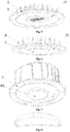
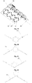
- a third LED bulb an integral LED bulb for implementing the foregoing method, including a heat conductive bracket 3 provided with a cooling fin, wherein a silver paste printed circuit 4 is embedded on the heat conductive bracket 3, and an LED chip is welded on the silver paste printed circuit 4, or a drive chip is further welded thereon, and a waterproof joint 10A with a cable is fixed to a connector fixing hole of the heat conductive bracket 3 through a cable fixing head 11A, as shown in Fig.5 .
- a slot 18 is provided to the heat conductive bracket 3, a bulb inner cover 6 is fixed to the slot in an embedding manner, and the bulb inner cover 6 covers the LED chip or the drive chip, as shown in Fig.6 .
- the heat conductive bracket 3 is fixed in a lens bracket 71 with a hang lug, and a lens 7 is provided at the lower end of the lens bracket 71, as shown in Fig.10 .
- Transparent silica gel for package is provided outside the LED chip
- the bulb inner cover 6 is provided outside the LED chip with the transparent silica gel
- fluorescent powder coating is provided to the inner layer of the bulb inner cover 6; or, no silica gel is packaged on the LED chip, and a concave inner cover 61 filled with transparent insulating heat conductive liquid is provided outside the LED chip, as shown in Fig.7 .
- the LED chip is soaked in the transparent insulating heat conductive liquid, a fluorescent material is provided in the transparent insulating heat conductive liquid, and the concave inner cover 61 is an elastic inner cover of a thin concave structure, as shown in Fig.8 .
- the LED chip may also be packaged by adopting a traditional package solution, namely, fluorescent powder is spray coated on the LED chip and transparent silica gel is covered thereon, and no bulb inner cover is used.
- the present invention is applied to agricultural production lighting, the number of the LED chips is configured according to the proportion of blue and red lights necessary for plants, and only the transparent silica gel is covered on the welded LED chip for package.
- a lamp may be constructed just by fixing the integral LED bulb in the present invention on the lamp used as an installation interface.
- a down lamp may be constructed by installing the integral LED bulb on a down lamp housing 101 with the installation interface;
- a ceiling lamp may be constructed by installing the integral LED bulb in a ceiling lamp head plate 103 with the installation interface and covering with a ceiling lamp housing 101.
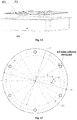
- a screw hole distribution circle (or the outer diameter of the hang lug) D1 for fixing the bulb and the diameter D2 of an installation interface opening of the lamp are influenced by the size of the used screw, and the diameter D1 is a value obtained by subtracting a diameter of a fixing screw cap and then subtracting a margin of 0.8-4 mm from the outer diameter D of the LED bulb; the diameter D2 of the installation interface opening is a value obtained by subtracting two times of a diameter of a fixing screw cap and then subtracting two times of the margin corresponding to the diameter D1 from the outer diameter D of the bulb; the value of the wire outlet hole distance L of the bulb is set according to the following table.
- the outer diameter D of the size of the bulb, the diameter D1 of the flange screw hole (or the outer diameter of the hang lug) distribution circle and the outer diameter D3 of the cooling fin are manufactured according to specified sizes, and the related sizes are set forth in Fig.15 and the following table: outer diameter D (mm) of bulb Diameter D 1 (mm) of screw hole distribution circle Diameter D 2 (mm) of instalation interface opening Wire outlet hole distance L(mm) Fixing screw specificatio n ⁇ (mm) Suitable power (W) 20 16 12 2 M1. 6 ⁇ 2. 5 30 25 20 2 M1. 6 ⁇ 3. 5 40 35 30 2 M1. 6 ⁇ 5 50 42 34 2 M2.
- the outer diameter D3 of the bulb radiator or the outer cover is not larger than D2-1; note 2: the diameter ⁇ of the bulb wire outlet hole is determined according to the size of the bulb connector (interface) plug.
- An oval LED street lamp using an installation interface bracket structure including an installation interface plate fixing bracket 112, wherein an installation interface plate 103 is provided at the lower part of the installation interface plate fixing bracket 112, an installation interface is provided to the installation interface plate 103, and an LED bulb 102 is provided to the installation interface; the installation interface plate fixing bracket 112 is connected to a lamp post 108; a lamp housing 101 is provided at the upper part of the installation interface plate fixing bracket 112, a lampshade 113 is provided outside the installation interface plate 103, and the lamp housing 101 matches with the lampshade 113 to form an oval shape.
- a wire harness connector 106 is provided to the installation interface plate fixing bracket 112, and the wire harness connector 106 is used for connecting a plurality of LED bulbs 102 to a power supply and a control circuit.
- the installation interface plate fixing bracket 112 includes a sleeve 116, the sleeve 116 is used for installing the lamp post 108, wire harness connector brackets 107 are provided on both sides of the sleeve 116, and the wire harness connector brackets 107 are used for installing the wire harness connector 106; a ring plate 114 is provided outside the sleeve 116 and the wire harness connector brackets 107, and the ring plate 114 is used for fixedly connecting the installation interface plate 103 to the installation interface plate fixing bracket 112, as shown in Fig.15 .
- a light penetration hole is provided to the lampshade 113;
- the installation interface includes a surface in contact with the LED bulb 102 and a hole connected to the LED bulb on the installation interface plate 103.
- a radiator interface opening and 6 flange fixing holes are provided to the installation interface of the installation interface plate 103, the flange fixing holes are used for fixing the LED bulb 102, and the radiator interface opening is used for enabling the LED bulb 102 to penetrate through the installation interface;
- the flange fixing holes are uniformly distributed at a diameter D1, and the diameter D1 is a value obtained by subtracting a diameter of a fixing screw cap and then subtracting a margin of 0.8-4 mm from the outer diameter D of the LED bulb 102;
- the diameter D2 of the radiator interface opening on the installation interface is a value obtained by subtracting two times of a diameter of a fixing screw cap and then subtracting two times of the margin corresponding to the diameter D1 from the outer diameter D of the bulb.
- the LED bulb 102 is installed on the bulb installation interface through
- the lamp in the embodiment uses the installation interface plate fixing bracket as the core, the installation interface plate fixing bracket provides an installation interface for the lamp post while providing a supporting interface for the installation interface plate, and the installation interface plate provides an installation interface for the LED bulb.
- the LED bulb and all of other auxiliary components are collectively installed and fixed to the installation interface plate fixing bracket, thus the LED street lamp is simple, practical and beautiful.
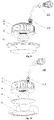
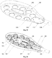
- An LED street lamp using a lamp housing as an installation interface bracket structure includes the lamp housing 101 punch formed by sheet metal via a stamping process, wherein an installation interface is provided to the lamp housing 101, an LED bulb 102 is provided to the installation interface, the lamp housing 101 is fixed to a lamp post 108 by a lamp post fixing element, and a decorative cover 103 is provided to the lamp housing 101.
- the LED street lamp using the lamp housing as the installation interface bracket structure further includes a wire harness connector 106, wherein the wire harness connector 106 is provided to the decorative cover 103, and the wire harness connector 106 is used for connecting a plurality of LED bulbs 102 to a power supply and a control circuit.
- the lamp housing 101 is elliptic, edgefolds for reinforcing the structural strength are provided at the inner and outer edges of the lamp housing 101, and the installation interface includes a surface in contact with the LED bulb 102 and a hole connected to the LED bulb, on the lamp housing 101.
- the lamp post fixing element includes a lamp post fixing bracket 112, a lamp post fixing bracket bolt 111 and a reinforcing plate 110, wherein the lamp post fixing bracket 112 and the reinforcing plate 110 are provided at the upper and lower sides of the lamp housing 101, and the lamp housing 101 is fixed to the lamp post 108 through the lamp post fixing bracket 112 and the reinforcing plate 110.
- a radiator interface opening and 6 flange fixing holes are provided to the installation interface of the lamp housing 101, the flange fixing holes are used for fixing the LED bulb 102, and the radiator interface opening is used for enabling the LED bulbs 102 to penetrate through the installation interface;
- the flange fixing holes are uniformly distributed at a diameter D1, and the diameter D1 is a value obtained by subtracting a diameter of a fixing screw cap and then subtracting a margin of 0.8-4 mm from the outer diameter D of the LED bulb 102;
- the diameter D2 of the radiator interface opening on the installation interface is a value obtained by subtracting two times of a diameter of a fixing screw cap and then subtracting two times of the margin corresponding to the diameter D1 from the outer diameter D of the bulb.
- the wire harness connector 106 is fixed to the decorative cover 103 through a wire harness connector bracket and screw 107.
- the lamp post fixing bracket 112 is fixed to the lamp housing 101 through the reinforcing plate 110 and the lamp post fixing bracket bolt 111, and the lamp post 108 is connected to the lamp post fixing bracket 112 through a lamp post fixing screw 109.
- Each LED bulb 102 is installed on the lamp housing 101 through bulb fixing screws 105, and the LED bulb 102 penetrates through an installation interface hole. The LED bulb 102 is installed on the installation interface from the lower side.
- a heat conductive pad 2 is provided between a flange or an installation flange and the installation interface.
- the heat conductive bracket 3 may also be fixed in a bulb outer cover 91 provided with the installation flange.
- the LED bulb 102 may also be installed on the lamp housing from the upper side, as shown in Fig.23 and Fig.24 .
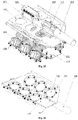
- An LED street lamp using a lamp housing as an installation interface bracket structure includes a lamp housing 101 punch formed by sheet metal; the lamp housing 101 includes a bracket panel folded to multiple pieces, an installation interface is provided to the bracket panel, and an LED bulb 102 is provided to the installation interface; the lamp housing 101 is fixed to a lamp post 108 through a lamp post fixing element.
- the LED street lamp using the lamp housing as the installation interface bracket structure further includes a wire harness connector 106, wherein the wire harness connector 106 is provided to the lamp housing 101, and the wire harness connector is used for connecting a plurality of LED bulbs 102 to a power supply and a control circuit.
- An edgefold for reinforcing the structural strength is provided at the edge of the lamp housing 101, and the installation interface includes a surface in contact with the LED bulb 102 and a hole connected to the LED, bulb on the lamp housing 101; a lamp post fixing hole used for connecting the lamp post 108 is formed in the upper part of the lamp post fixing bracket 112.
- the lamp post fixing element includes a lamp post fixing bracket 112, a lamp post fixing bracket bolt 111 and a reinforcing plate 110, wherein the lamp post fixing bracket 112 and the reinforcing plate 110 are provided at the upper and lower sides of the lamp housing 101, and the lamp housing 101 is fixed to the lamp post 108 through the lamp post fixing bracket 112 and the reinforcing plate 110;
- the lamp housing 101 includes three bracket panels which are folded to form an angle, a planar bracket is provided at the lower part of the lamp post fixing bracket 112, and the lamp post fixing bracket 112 is fixed to the bracket panel at the center of the lamp housing 101 from the upper side or the lower side of the lamp housing 101.
- 6 flange fixing holes and a radiator interface opening are provided to the installation interface, the flange fixing holes are used for fixing each LED bulb 102, and the radiator interface opening is used for enabling the LED bulb 102 to penetrate through the installation interface;
- the 6 flange fixing holes are uniformly distributed at a diameter D1, and the diameter D1 is a value obtained by subtracting a diameter of a fixing screw cap and then subtracting a margin of 0.8-4 mm from the outer diameter D of the LED bulb 102;
- the diameter D2 of the radiator interface opening is a value obtained by subtracting two times of a diameter of a fixing screw cap and then subtracting two times of the margin corresponding to the diameter D1 from the bulb outer diameter D.
- the LED bulb 102 is installed on the installation interface through a bulb fixing screw 105
- the wire harness connector 106 is installed on the lamp housing 101 through a wire harness connector bracket and screw 107
- the lamp post fixing bracket 112 and the reinforcing plate 110 are fixed to the lamp housing 101 through the lamp post fixing bracket bolt 111
- the lamp post 108 is connected to the lamp post fixing bracket 112 through a lamp post fixing screw 109.
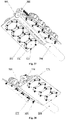
- bracket panels on both sides may also be provided downwards to form an angle, as shown in Fig.28 and Fig.32 .
- the lamp housing 101 includes two bracket panels which are folded upwards to form an angle, at this time, a triangular bracket is provided at the lower part of the lamp post fixing bracket 112 and is V-shaped, as shown in Fig.29 and Fig.33 .
- the lamp housing 101 includes two bracket panels which are folded downwards to form an angle, at this time, a triangular bracket is provided at the lower part of the lamp post fixing bracket 112 and is inverted V-shaped, as shown in Fig.30 and Fig.34 .
- the bulb in the case of an accident, may be conveniently maintained and changed just by directly detaching the bulb 102 from the lamp housing 101, as shown in Fig.25 .
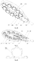
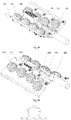
- An LED street lamp using an extrusion type installation interface bracket structure including an extrusion type installation interface bracket 103, wherein the extrusion type installation interface bracket 103 is fixed to a lamp post 108; the extrusion type installation interface bracket 103 includes a lamp post fixing sleeve, bracket panels are provided on both sides of the lamp post fixing sleeve, and an installation interface used for installing an LED bulb 102 is provided to each bracket panel; the LED bulb 102 with waterproof and dustproof functions and provided with a radiator is installed on the installation interface.
- the LED street lamp using the extrusion type installation interface bracket structure further includes a wire harness connector 106, wherein the wire harness connector 106 is provided to the lamp post fixing sleeve, and the wire harness connector 106 is used for connecting a plurality of LED bulbs 102 to a power supply and a control circuit.
- bracket 103 In the extrusion type installation interface bracket 103, the bracket panels on both sides are provided upwards to form an angle, as shown in Fig.40 ; a lamp post seal head 101 is provided at one end of the lamp post fixing sleeve, and the other end of the lamp post fixing sleeve is fixed to the lamp post 108 through a lamp post fixing screw 109; the installation interface includes a surface in contact with the LED bulb 102 and a hole connected to the LED bulb, on the bracket panels.
- a radiator interface opening and 6 flange fixing holes are provided to the installation interface, the flange fixing holes are used for fixing the LED bulb 102, and the radiator interface opening is used for enabling the LED bulb 102 to penetrate through the installation interface;
- the 6 flange fixing holes are uniformly distributed at a diameter D1, and the diameter D1 is a value obtained by subtracting a diameter of a fixing screw cap and then subtracting a margin of 0.8-4 mm from the outer diameter D of the LED bulb 102;
- the diameter D2 of the radiator interface opening is a value obtained by subtracting two times of a diameter of a fixing screw cap and then subtracting two times of the margin corresponding to the diameter D1 from the bulb outer diameter D.
- the LED bulb 102 is installed on the installation interface through a bulb fixing screw 105.
- the wire harness connector 106 is installed on the lamp post fixing sleeve through a wire harness connector bracket and fixing screw 107.
- bracket panels may also be provided downwards to form an angle, as shown in Fig.37 and Fig.41 .
- bracket panels may also be connected and provided upwards to form an angle, as shown in Fig.38 and Fig.42 .
- bracket panels may also be connected and provided downwards to form an angle, as shown in Fig.39 and Fig.43 .
- the bulb in the case of an accident, may be conveniently maintained and changed just by directly detaching the bulb 102 from the extrusion type installation interface bracket 103, as shown in Fig.35 .
- the lamp in the embodiment adopts the extrusion type installation interface bracket as the main component, the bracket panels of the extrusion type installation interface bracket provide installation supporting interfaces for the LED bulb, the LED bulb and other auxiliary components are overall collectively installed on the extrusion type installation interface bracket, thereby being simple in structure, low in manufacturing cost and convenient to install, use and maintain.
- the extrusion type installation interface bracket performs such functions of the lamp housing as preventing water and preventing dust and the like at the same time.
Landscapes
- Engineering & Computer Science (AREA)
- General Engineering & Computer Science (AREA)
- Physics & Mathematics (AREA)
- Microelectronics & Electronic Packaging (AREA)
- Optics & Photonics (AREA)
- Manufacturing & Machinery (AREA)
- Non-Portable Lighting Devices Or Systems Thereof (AREA)
- Arrangement Of Elements, Cooling, Sealing, Or The Like Of Lighting Devices (AREA)
- Fastening Of Light Sources Or Lamp Holders (AREA)
- Securing Globes, Refractors, Reflectors Or The Like (AREA)
- Led Device Packages (AREA)
Claims (15)
- Procédé de construction d'une ampoule à diode électroluminescente DEL (102) dotée d'une interchangeabilité et d'une universalité élevées, comprenant :l'encastrement d'un circuit imprimé en pâte d'argent (4) sur un support (3) thermo-conducteur fritté par un matériau thermo-conducteur non métallique et muni d'une ailette de refroidissement, etensuite, le soudage d'une puce DEL ou encore le soudage d'une puce d'entraînement, sur le circuit imprimé en pâte d'argent (4) afin de former l'ampoule à DEL,où un fourreau intérieur d'ampoule (6) est fixé au niveau du support thermo-conducteur (3) en faisant une fente (18), et la puce DEL ou la puce d'entraînement est enveloppée dans le fourreau intérieur d'ampoule (6) ;où un fourreau extérieur d'ampoule (91) ou un circlip de lentille (8) et une lentille (7) sont en outre fixés au support thermo-conducteur (3) en faisant la fente (18), et une structure de bride pour l'installation est en outre frittée sur le support thermo-conducteur (3) ; ou le support thermo-conducteur (3) est fixé dans le fourreau extérieur d'ampoule (91), muni d'une bride d'installation ; ou le support thermo-conducteur (3) est fixé dans un support de lentille (71) muni d'une patte de suspension, et la lentille (7) est mise en place sur une extrémité inférieure du support de lentille (71).
- Procédé de construction d'une ampoule à DEL (102) dotée d'une interchangeabilité et d'une universalité élevées selon la revendication 1, dans lequel le diamètre extérieur d'ampoule D de l'ampoule à DEL (102) et la puissance W de l'ampoule à DEL (102) construite satisfont à une relation W = 1,1812e0,0361D, des valeurs numériques discrètes sont choisies pour D sur la courbe de la relation W = 1,1812e0,0361D pour construire une pluralité d'ampoules à DEL avec des diamètres extérieurs d'ampoule fixés, afin d'améliorer l'interchangeabilité et l'universalité des ampoules à DEL (102) ;
où, sur la courbe de relation W = 1,1812e0,0361D, avec 20 mm utilisés en tant que limite inférieure du diamètre extérieur d'ampoule D et 130 mm utilisés en tant que limite supérieure, la courbe de relation est divisée en 12 segments dont chacun est fixé à 10 mm afin de former un nombre limité de spécifications de diamètres extérieurs, et l'interchangeabilité et l'universalité des ampoules à DEL (102) sont en outre améliorées par la faible quantité de spécifications de diamètres extérieurs d'ampoule ; 6 trous de fixation de bride sur le support thermo-conducteur (3) avec la bride sont distribués uniformément au niveau d'un diamètre D1, et le diamètre D1 est une valeur obtenue en soustrayant un diamètre d'une tête de vis de fixation et ensuite en soustrayant une marge de 0,8 à 4 mm du diamètre extérieur D de l'ampoule ; le diamètre D2 d'une ouverture d'interface d'installation de l'ampoule à DEL sur une lampe est une valeur obtenue en soustrayant deux fois un diamètre d'une tête de vis de fixation et en soustrayant ensuite deux fois la marge correspondant au diamètre D1 du diamètre extérieur D de l'ampoule ; l'interface d'installation de l'ampoule à DEL comprend une surface en contact avec l'ampoule à DEL et un trou connecté à l'ampoule à DEL sur la lampe. - Procédé de construction d'une ampoule à DEL (102) dotée d'une interchangeabilité et d'une universalité élevées selon la revendication 1, dans lequel de la poudre fluorescente est revêtue par pulvérisation sur la puce DEL, et du gel de silice transparent la recouvre ; ou le nombre de puces DEL est configuré en fonction d'une proportion de lumières bleues et rouges nécessaires pour des installations, et uniquement du gel de silice transparent recouvre la puce DEL soudée pour le conditionnement.
- Ampoule à DEL intégrée construite par le procédé selon l'une des revendications 1 à 3, comprenant un support thermo-conducteur (3) muni d'une ailette de refroidissement, où un circuit imprimé à pâte d'argent (4) est encastré sur le support thermo-conducteur (3) qui est fritté par un matériau thermo-conducteur non métallique, et une puce DEL est soudée sur le circuit imprimé à pâte d'argent (4), ou une puce d'entraînement est en outre soudée dessus ;où une fente (18) est mise en place au niveau du support thermo-conducteur (3), un fourreau intérieur d'ampoule est encastré et fixé dans la fente (18), et le fourreau intérieur d'ampoule (6) recouvre la puce DEL ou la puce d'entraînement ;où une structure de bride d'installation est mise en place au niveau d'un bord du support thermo-conducteur (3), une fente (18) est en outre mise en place à l'extérieur du fourreau intérieur d'ampoule (6), un fourreau extérieur d'ampoule (9) ou un circlip de lentille (8) et une lentille (7) sont en outre encastrés dans la fente (18) ; ou le support thermo-conducteur (3) est fixé dans un fourreau extérieur d'ampoule (91) muni d'une bride d'installation ; ou le support thermo-conducteur (3) est fixé dans un support de lentille (71) muni d'une patte de suspension, et la lentille (7) est mise en place au niveau d'une extrémité inférieure du support de lentille (71).
- Ampoule à DEL intégrée selon la revendication 4, dans laquelle de la poudre fluorescente est revêtue par pulvérisation sur la puce DEL, et du gel de silice transparent recouvre l'extérieur de la poudre fluorescente ; ou uniquement du gel de silice transparent recouvre la puce DEL ; ou uniquement du gel de silice transparent pour conditionnement est mis en place à l'extérieur de la puce DEL, le fourreau intérieur d'ampoule (6) est mis en place à l'extérieur de la puce DEL avec du gel de silice transparent et la puce d'entraînement, et un revêtement de poudre fluorescente est appliqué au niveau de la couche intérieure du fourreau intérieur d'ampoule (6) ; ou, aucun gel de silice n'est accumulé sur la puce DEL, un fourreau intérieur concave (61), rempli avec un liquide thermo-conducteur isolant transparent, est mis à l'extérieur de la puce DEL, la puce DEL est trempée dans le liquide thermo-conducteur isolant transparent, le matériau fluorescent est mis dans le liquide thermo-conducteur isolant transparent et le fourreau intérieur concave (61) est un fourreau intérieur élastique à base d'une structure concave fine.
- Ampoule à DEL intégrée selon la revendication 4, dans laquelle la fente (18) est mise en place au niveau du support thermo-conducteur (3), le fourreau extérieur d'ampoule (9) est directement encastré dans la fente par adhésion, ou la lentille (7) est attachée par le circlip de lentille (8) et le circlip de lentille (8) est encastré dans la fente (18) par adhésion.
- Lampe utilisant l'ampoule à DEL selon la revendication 4, comprenant une interface d'installation, où l'ampoule à DEL est mise en place sur l'interface d'installation.
- Lampe selon la revendication 7, où la lampe est une lampe de rue à DEL ovale, la lampe de rue à DEL ovale comprend un support (112) de fixation de plaque d'interface d'installation, une plaque (103) d'interface d'installation est mise en place au niveau de la partie inférieure du support (112) de fixation de plaque d'interface d'installation, une interface d'installation est mise en place au niveau de la plaque (103) d'interface d'installation, et une ampoule à DEL (102) est mise en place au niveau de l'interface d'installation, le support (112) de fixation de plaque d'interface d'installation est connecté à un poteau de lampe (108) ; un boîtier de lampe (101) est mis en place au niveau de la partie supérieure du support (112) de fixation de plaque d'interface d'installation, un abat-jour (113) est mis en place à l'extérieur de la plaque (103) d'interface d'installation, et le boîtier de lampe (101) est ajusté avec l'abat-jour (113) afin de former une conformation ovale.
- Lampe selon la revendication 8, dans laquelle un connecteur de faisceau (106) est mis en place au niveau du support (112) de fixation de plaque d'interface d'installation, et le connecteur de faisceau (106) est utilisé pour la connexion d'une pluralité d'ampoules à DEL (102) à une alimentation électrique et à un circuit de contrôle ;où le support (112) de fixation de plaque d'interface d'installation comprend un manchon (116), le manchon (116) est utilisé pour l'installation d'un poteau de lampe (108), des supports (107) de connecteur de faisceau sont mis en place sur deux côtés du manchon (116), et les supports (107) de connecteur de faisceau sont utilisés pour l'installation du connecteur de faisceau (106) ; une plaque annulaire (114) est mise en place à l'extérieur du manchon (116) et des supports (107) de connecteur de faisceau, et la plaque annulaire (114) est utilisée pour connecter de manière fixe une plaque (103) d'interface d'installation au support (112) de fixation de plaque d'interface d'installation ;où un trou de pénétration de lumière et un trou de drainage d'eau sont mis en place au niveau de l'abat-jour (113) ; l'interface d'installation comprend une surface en contact avec l'ampoule à DEL (102) et un trou connecté au niveau de l'ampoule à DEL sur la plaque (103) d'interface d'installation.
- Lampe selon la revendication 7, où la lampe est une lampe de rue à DEL, un boîtier de lampe est utilisé en tant que structure de support d'interface d'installation, la lampe de rue à DEL comprend un boîtier de lampe (101) formé par une tôle métallique par le biais d'un procédé d'emboutissage, une interface d'installation est mise en place au niveau du boîtier de lampe (101), le boîtier de lampe (101) est fixé à un poteau de lampe (108) par un élément de fixation de poteau de lampe, et un revêtement décoratif (103) est déposé au niveau du boîtier de lampe (101).
- Lampe selon la revendication 10, comprenant en outre un connecteur de faisceau (106), où le connecteur de faisceau (106) est mis en place au niveau du revêtement décoratif (103), et le connecteur de faisceau (106) est utilisé pour la connexion d'une pluralité d'ampoules à DEL (103) à une alimentation électrique et à un circuit de contrôle ;où le boîtier de lampe (101) est elliptique, des plis de bord pour le renforcement de la résistance structurelle sont mis en place au niveau des bords intérieur et extérieur du boîtier de lampe (101), et l'interface d'installation comprend une surface en contact avec l'ampoule à DEL (102) et un trou connecté à l'ampoule à DEL sur le boîtier de lampe (101) ;où l'élément de fixation de poteau de lampe comprend un support (112) de fixation de poteau de lampe, un boulon (11) de support de fixation de poteau de lampe et une plaque de renfort (110), le support (112) de fixation de poteau de lampe et la plaque de renfort (110) sont mis en place sur des côtés supérieur et inférieur du boîtier de lampe (101), et le boîtier de lampe (101) est fixé au niveau du poteau de lampe (108) par le support (112) de fixation de poteau de lampe et la plaque de renfort (110).
- Lampe selon la revendication 7, où la lampe est une lampe de rue à DEL, la lampe de rue à DEL utilisant un boîtier de lampe en tant que structure de support d'interface d'installation comprend un boîtier de lampe (101) formé par perforation d'une tôle métallique ; le boîtier de lampe (101) comprend un panneau de support plié en de multiples parties, une interface d'installation est mise en place au niveau du panneau de support, et une ampoule à DEL (102) est mise en place au niveau de l'interface d'installation ; le boîtier de lampe (101) est fixé à un poteau de lampe (108) par un élément de fixation de poteau de lampe.
- Lampe selon la revendication 12, comprenant en outre un connecteur de faisceau (106), où le connecteur de faisceau (106) est mis en place au niveau du boîtier de lampe (101), et le connecteur de faisceau (106) est utilisé pour la connexion d'une pluralité d'ampoules à DEL (102) à une alimentation électrique et à un circuit de contrôle ;où un pli de bord pour le renforcement de la résistance structurelle est mis en place au niveau du bord du boîtier de lampe (101), et l'interface d'installation comprend une surface en contact avec l'ampoule à DEL (102) et un trou connecté à l'ampoule à DEL sur le boîtier de lampe (101) ; un trou de fixation de poteau de lampe utilisé pour la connexion du poteau de lampe (108) est formé dans la partie supérieure du support (112) de fixation de poteau de lampe ;où l'élément de fixation de poteau de lampe comprend un support (112) de fixation de poteau de lampe (112), un boulon (111) de support de fixation de poteau de lampe et une plaque de renfort (110), où le support (112) de fixation de poteau de lampe et la plaque de renfort (110) sont mis en place sur des côtés supérieur et inférieur du boîtier de lampe (101), et le boîtier de lampe (101) est fixé au poteau de lampe (108) par le support (112) de fixation de poteau de lampe (112) et la plaque de renfort (110) ; le boîtier de lampe (101) comprend trois panneaux de support qui sont pliés pour former un angle, un support planaire est mis en place au niveau de la partie inférieure du support (112) de fixation de poteau de lampe, et le support (112) de fixation de poteau de lampe est fixé au panneau de support au centre du boîtier de lampe (101) à partir du côté supérieur ou du côté inférieur du boîtier de lampe (101) ; ou le boîtier de lampe (101) comprend deux panneaux de support qui sont pliés pour former un angle, le support (112) de fixation de poteau de lampe est fixé aux panneaux de support mis en place pour former l'angle à partir du côté supérieur ou du côté inférieur du boîtier de lampe (101), et un support triangulaire est mis en place au niveau de la partie inférieure du support (112) de fixation de poteau de lampe et est inversé en forme de V ou en forme de V.
- Lampe selon la revendication 7, où la lampe est une lampe de rue à DEL, la lampe de rue à DEL comprend un support (103) d'interface d'installation de type extrusion de métal, le support (103) d'interface d'installation de type extrusion de métal est fixé à un poteau de lampe (108) ; le support (103) d'interface d'installation de type extrusion de métal comprend un manchon de fixation de poteau de lampe, des panneaux de support sont mis en place sur les deux côtés du manchon de fixation de poteau de lampe, et une interface d'installation utilisée pour l'installation d'une ampoule à DEL (102) est mise en place au niveau de chaque panneau de support ; l'ampoule à DEL (102) est installée sur l'interface d'installation.
- Lampe selon la revendication 14, comprenant en outre un connecteur de faisceau (106), où le connecteur de faisceau (106) est mis en place au niveau d'un manchon de fixation de poteau de lampe, et le connecteur de faisceau (106) est utilisé pour connecter une pluralité d'ampoules à DEL (102) à une alimentation électrique et à un circuit de contrôle ;
où, dans le support (103) d'interface d'installation de type extrusion, les panneaux de support sur les deux côtés sont mis en place afin de former un angle ; un tête de scellement (101) de poteau de lampe est mise en place sur une extrémité du manchon de fixation de poteau de lampe, et l'autre extrémité du manchon de fixation de poteau de lampe est fixée au poteau de lampe (108) par une vis (109) de fixation de poteau de lampe ; l'interface d'installation comprend une surface en contact avec l'ampoule à DEL (102) et un trou connecté à l'ampoule à DEL sur les panneaux de support.
Applications Claiming Priority (6)
| Application Number | Priority Date | Filing Date | Title |
|---|---|---|---|
| CN201210253805.8A CN102818182B (zh) | 2012-07-23 | 2012-07-23 | 一种采用灯壳作为安装界面支架结构的led路灯 |
| CN201210253546.9A CN102818148B (zh) | 2012-07-23 | 2012-07-23 | 互换性和通用性强的led灯泡构成方法及一体式led灯泡 |
| CN201210253600.XA CN102818173B (zh) | 2012-07-23 | 2012-07-23 | 采用灯壳作为安装界面支架结构的led路灯 |
| CN201210253599.0A CN102818172B (zh) | 2012-07-23 | 2012-07-23 | 一种采用安装界面支架结构的卵形led路灯 |
| CN201210253769.5A CN102818179B (zh) | 2012-07-23 | 2012-07-23 | 一种采用挤压型安装界面支架结构的led路灯 |
| PCT/CN2013/000877 WO2014015653A1 (fr) | 2012-07-23 | 2013-07-23 | Procédé de formation d'ampoule à del hautement interchangeable et à universalité élevée et ampoule à del intégrée et lampe |
Publications (3)
| Publication Number | Publication Date |
|---|---|
| EP2886933A1 EP2886933A1 (fr) | 2015-06-24 |
| EP2886933A4 EP2886933A4 (fr) | 2016-04-27 |
| EP2886933B1 true EP2886933B1 (fr) | 2018-04-18 |
Family
ID=49996546
Family Applications (1)
| Application Number | Title | Priority Date | Filing Date |
|---|---|---|---|
| EP13822624.6A Not-in-force EP2886933B1 (fr) | 2012-07-23 | 2013-07-23 | Procédé de formation d'ampoule à del hautement interchangeable et à universalité élevée et ampoule à del intégrée et lampe |
Country Status (5)
| Country | Link |
|---|---|
| US (1) | US9625111B2 (fr) |
| EP (1) | EP2886933B1 (fr) |
| JP (1) | JP6108642B2 (fr) |
| KR (1) | KR101778867B1 (fr) |
| WO (1) | WO2014015653A1 (fr) |
Families Citing this family (17)
| Publication number | Priority date | Publication date | Assignee | Title |
|---|---|---|---|---|
| US9255674B2 (en) | 2012-10-04 | 2016-02-09 | Once Innovations, Inc. | Method of manufacturing a light emitting diode lighting assembly |
| US10240765B2 (en) | 2013-07-25 | 2019-03-26 | Abl Research Group, Llc | Arc modular light devices, systems, and methods |
| US9995472B2 (en) * | 2013-07-25 | 2018-06-12 | Abl Research Group, Llc | Arc modular LED light fixture |
| EP3179153A1 (fr) * | 2015-12-11 | 2017-06-14 | Epistar Corporation | Appareil d'éclairage |
| CN105674224B (zh) * | 2016-03-30 | 2018-09-18 | 湖南粤港模科实业有限公司 | 一种插拔式led芯片散热器一体化光源与透镜结构 |
| US10353142B2 (en) | 2017-04-19 | 2019-07-16 | Omachron Intellectual Property Inc. | LED light source |
| US10514489B2 (en) | 2017-04-19 | 2019-12-24 | Omachron Intellectual Property Inc. | LED light source |
| CA3210016C (fr) * | 2017-04-19 | 2025-10-14 | Omachron Intellectual Property Inc. | Source de lumiere a del |
| US10466411B2 (en) | 2017-04-19 | 2019-11-05 | Omachron Intellectual Property Inc. | LED light source |
| DE102018116809A1 (de) * | 2018-07-11 | 2020-01-16 | Itz Innovations- Und Technologiezentrum Gmbh | Variabel anpassbare Mastaußenleuchte |
| JP7070836B2 (ja) * | 2018-09-25 | 2022-05-18 | 東芝ライテック株式会社 | 照明装置 |
| US11969068B2 (en) * | 2019-07-25 | 2024-04-30 | Kupa, Inc. | Cordless nail gel curing lamp with interchangeable surface features |
| US11168879B2 (en) | 2020-02-28 | 2021-11-09 | Omachron Intellectual Property Inc. | Light source |
| CN111520661A (zh) * | 2020-06-04 | 2020-08-11 | 中山市亮美城照明科技有限公司 | 固定式灯具 |
| CN113007675A (zh) * | 2021-03-23 | 2021-06-22 | 苏州欧普照明有限公司 | 一种光电核心模块及灯具 |
| US12452979B2 (en) | 2023-03-29 | 2025-10-21 | Kupa, Inc. | Multiple lighting mode LED lamp |
| USD1072308S1 (en) | 2023-03-29 | 2025-04-22 | Kupa, Inc. | LED lamp |
Family Cites Families (29)
| Publication number | Priority date | Publication date | Assignee | Title |
|---|---|---|---|---|
| JP4915058B2 (ja) * | 2005-06-06 | 2012-04-11 | パナソニック株式会社 | Led部品およびその製造方法 |
| US20070200133A1 (en) * | 2005-04-01 | 2007-08-30 | Akira Hashimoto | Led assembly and manufacturing method |
| TWI290777B (en) * | 2006-02-27 | 2007-12-01 | Guei-Fang Chen | Lighting device with light emitting diode |
| DE202008012317U1 (de) * | 2007-09-14 | 2008-11-20 | Anteya Technology Corporation, Niaosong | Beleuchtungsvorrichtung aus streifenförmigen Leuchtdiodenlampen |
| JP5060357B2 (ja) * | 2008-03-25 | 2012-10-31 | スタンレー電気株式会社 | 車両用前照灯 |
| EP2105659A1 (fr) * | 2008-03-27 | 2009-09-30 | Wen-Long Chyn | Lampe à Del à efficacité améliorée |
| US7641363B1 (en) * | 2008-06-16 | 2010-01-05 | Li-Hong Technological Co., Ltd. | LED streetlight structure |
| JP3144750U (ja) * | 2008-06-30 | 2008-09-11 | 麗鴻科技股▲ふん▼有限公司 | Led街灯 |
| CN105444014A (zh) * | 2009-05-04 | 2016-03-30 | 皇家飞利浦电子股份有限公司 | 包括设置在半透明外壳内的光发射器的光源 |
| JP2011003340A (ja) * | 2009-06-17 | 2011-01-06 | Wun Song Hu | Ledやledsmd電球と電灯の有効な放熱構造 |
| JP2011030463A (ja) * | 2009-07-30 | 2011-02-17 | Toyoda Gosei Co Ltd | 水中用照明とこれを用いた養殖装置 |
| TWM383082U (en) * | 2009-12-04 | 2010-06-21 | Qbas Tech Co Ltd | Street lamp capable of adjusting illuminating range thereof and having LEDs as light source |
| US8562161B2 (en) * | 2010-03-03 | 2013-10-22 | Cree, Inc. | LED based pedestal-type lighting structure |
| JP2011228300A (ja) * | 2010-04-21 | 2011-11-10 | Chang Wook | 大角度led光源及び大角度高放熱性led照明灯 |
| JP5053418B2 (ja) * | 2010-05-17 | 2012-10-17 | シャープ株式会社 | 発光装置、照明装置および車両用前照灯 |
| JP4602477B1 (ja) * | 2010-06-16 | 2010-12-22 | 隆泰 佐藤 | 照明装置 |
| CN201827857U (zh) * | 2010-09-28 | 2011-05-11 | 南京汉德森科技股份有限公司 | Led光源的导热结构 |
| JP2012109147A (ja) * | 2010-11-18 | 2012-06-07 | Stanley Electric Co Ltd | Led発光ユニット |
| KR101781424B1 (ko) * | 2010-11-26 | 2017-09-26 | 서울반도체 주식회사 | 엘이디 조명기구 |
| CN202303052U (zh) * | 2011-10-27 | 2012-07-04 | 贵州光浦森光电有限公司 | 一种led路灯 |
| CN102777795B (zh) * | 2012-07-23 | 2014-08-13 | 贵州光浦森光电有限公司 | 通用型led灯泡构成方法及荧光内罩的法兰固定式led灯泡 |
| CN102818148B (zh) * | 2012-07-23 | 2014-11-26 | 贵州光浦森光电有限公司 | 互换性和通用性强的led灯泡构成方法及一体式led灯泡 |
| CN102818173B (zh) * | 2012-07-23 | 2015-04-15 | 贵州光浦森光电有限公司 | 采用灯壳作为安装界面支架结构的led路灯 |
| CN102818182B (zh) * | 2012-07-23 | 2014-08-06 | 贵州光浦森光电有限公司 | 一种采用灯壳作为安装界面支架结构的led路灯 |
| CN202647351U (zh) * | 2012-07-23 | 2013-01-02 | 贵州光浦森光电有限公司 | 荧光内罩的法兰固定式led灯泡 |
| CN102829408B (zh) * | 2012-07-23 | 2014-09-24 | 贵州光浦森光电有限公司 | 通用型led灯泡构成方法及液态荧光法兰固定式led灯泡 |
| CN102777796B (zh) * | 2012-07-23 | 2014-09-10 | 贵州光浦森光电有限公司 | 通用型led灯泡构成方法及液态荧光的挂耳固定式led灯泡 |
| CN102818172B (zh) * | 2012-07-23 | 2014-09-10 | 贵州光浦森光电有限公司 | 一种采用安装界面支架结构的卵形led路灯 |
| CN102818179B (zh) * | 2012-07-23 | 2014-08-06 | 贵州光浦森光电有限公司 | 一种采用挤压型安装界面支架结构的led路灯 |
-
2013
- 2013-07-23 WO PCT/CN2013/000877 patent/WO2014015653A1/fr not_active Ceased
- 2013-07-23 KR KR1020157004346A patent/KR101778867B1/ko not_active Expired - Fee Related
- 2013-07-23 EP EP13822624.6A patent/EP2886933B1/fr not_active Not-in-force
- 2013-07-23 JP JP2015523369A patent/JP6108642B2/ja not_active Expired - Fee Related
- 2013-07-23 US US14/416,513 patent/US9625111B2/en not_active Expired - Fee Related
Non-Patent Citations (1)
| Title |
|---|
| None * |
Also Published As
| Publication number | Publication date |
|---|---|
| JP2016500194A (ja) | 2016-01-07 |
| KR20150086224A (ko) | 2015-07-27 |
| EP2886933A4 (fr) | 2016-04-27 |
| WO2014015653A1 (fr) | 2014-01-30 |
| KR101778867B1 (ko) | 2017-09-26 |
| JP6108642B2 (ja) | 2017-04-05 |
| EP2886933A1 (fr) | 2015-06-24 |
| US9625111B2 (en) | 2017-04-18 |
| US20150247612A1 (en) | 2015-09-03 |
Similar Documents
| Publication | Publication Date | Title |
|---|---|---|
| EP2886933B1 (fr) | Procédé de formation d'ampoule à del hautement interchangeable et à universalité élevée et ampoule à del intégrée et lampe | |
| US9709248B2 (en) | Method for constructing universal LED bulb, snap ring structured LED bulb and LED lamp | |
| EP2876356B1 (fr) | Procédé de fabrication d'ampoule à del universelle et ampoule à del de type à anneau élastique de bride et lampe à del | |
| EP2876358B1 (fr) | Procédé de fabrication d'ampoule à del universelle et ampoule à del de type à anneau élastique interne de bride et lampe | |
| US9709220B2 (en) | Method for constructing universal LED bulb and snap ring lens type LED bulb and LED lamp | |
| KR20150052842A (ko) | 호환성과 범용성이 강한 led 전구 구성방법 및 플랜지형 서포트 led 전구 및 led 조명기구 | |
| CN102777838B (zh) | 一种通用型led灯泡构成方法及液态荧光的led灯泡 | |
| CN102818199B (zh) | 一种led吸顶灯 | |
| CN202647507U (zh) | 一种多光源led吸顶灯 | |
| CN102777828B (zh) | 采用挤压型双面散热器为灯具主体结构的led路灯 | |
| CN102798006B (zh) | 一种矩形多光源led筒灯 | |
| CN102777839B (zh) | 一种多光源led吸顶灯 | |
| CN202056580U (zh) | Led泛光照明灯具模组 | |
| CN102818184B (zh) | 采用双面散热器和灯壳支架结构的led隧道灯 | |
| CN102829408B (zh) | 通用型led灯泡构成方法及液态荧光法兰固定式led灯泡 | |
| CN202691708U (zh) | 一种矩形多光源led筒灯 | |
| CN209213603U (zh) | 一种节能型led灯壳体 | |
| CN202868351U (zh) | Led螺口灯 |
Legal Events
| Date | Code | Title | Description |
|---|---|---|---|
| PUAI | Public reference made under article 153(3) epc to a published international application that has entered the european phase |
Free format text: ORIGINAL CODE: 0009012 |
|
| 17P | Request for examination filed |
Effective date: 20150219 |
|
| AK | Designated contracting states |
Kind code of ref document: A1 Designated state(s): AL AT BE BG CH CY CZ DE DK EE ES FI FR GB GR HR HU IE IS IT LI LT LU LV MC MK MT NL NO PL PT RO RS SE SI SK SM TR |
|
| AX | Request for extension of the european patent |
Extension state: BA ME |
|
| DAX | Request for extension of the european patent (deleted) | ||
| RA4 | Supplementary search report drawn up and despatched (corrected) |
Effective date: 20160324 |
|
| RIC1 | Information provided on ipc code assigned before grant |
Ipc: F21V 29/00 20150101ALI20160405BHEP Ipc: F21W 131/101 20060101ALI20160405BHEP Ipc: F21Y 115/10 20160101ALI20160405BHEP Ipc: F21W 111/06 20060101ALI20160405BHEP Ipc: F21V 23/06 20060101ALI20160405BHEP Ipc: F21S 8/00 20060101ALI20160405BHEP Ipc: F21V 17/00 20060101ALI20160405BHEP Ipc: F21S 2/00 20160101AFI20160405BHEP Ipc: F21V 19/00 20060101ALI20160405BHEP Ipc: F21W 131/103 20060101ALI20160405BHEP Ipc: F21V 31/00 20060101ALI20160405BHEP |
|
| STAA | Information on the status of an ep patent application or granted ep patent |
Free format text: STATUS: EXAMINATION IS IN PROGRESS |
|
| 17Q | First examination report despatched |
Effective date: 20170523 |
|
| RIC1 | Information provided on ipc code assigned before grant |
Ipc: F21V 23/06 20060101ALI20170717BHEP Ipc: F21Y 115/10 20160101ALN20170717BHEP Ipc: F21S 8/00 20060101ALI20170717BHEP Ipc: F21V 29/00 20150101ALI20170717BHEP Ipc: F21W 131/101 20060101ALI20170717BHEP Ipc: F21V 19/00 20060101ALI20170717BHEP Ipc: F21V 31/00 20060101ALI20170717BHEP Ipc: F21S 2/00 20160101AFI20170717BHEP Ipc: F21W 131/103 20060101ALI20170717BHEP Ipc: F21V 17/00 20060101ALI20170717BHEP Ipc: F21W 111/06 20060101ALI20170717BHEP |
|
| REG | Reference to a national code |
Ref country code: DE Ref legal event code: R079 Ref document number: 602013036202 Country of ref document: DE Free format text: PREVIOUS MAIN CLASS: F21S0008000000 Ipc: F21S0002000000 |
|
| GRAP | Despatch of communication of intention to grant a patent |
Free format text: ORIGINAL CODE: EPIDOSNIGR1 |
|
| RIC1 | Information provided on ipc code assigned before grant |
Ipc: F21S 2/00 20160101AFI20170922BHEP Ipc: F21V 23/06 20060101ALI20170922BHEP Ipc: F21V 29/00 20150101ALI20170922BHEP Ipc: F21S 8/00 20060101ALI20170922BHEP Ipc: F21V 17/00 20060101ALI20170922BHEP Ipc: F21Y 115/10 20160101ALN20170922BHEP Ipc: F21W 131/103 20060101ALI20170922BHEP Ipc: F21V 31/00 20060101ALI20170922BHEP Ipc: F21W 111/06 20060101ALI20170922BHEP Ipc: F21V 19/00 20060101ALI20170922BHEP Ipc: F21W 131/101 20060101ALI20170922BHEP |
|
| STAA | Information on the status of an ep patent application or granted ep patent |
Free format text: STATUS: GRANT OF PATENT IS INTENDED |
|
| RIC1 | Information provided on ipc code assigned before grant |
Ipc: F21V 17/00 20060101ALI20170929BHEP Ipc: F21Y 115/10 20160101ALN20170929BHEP Ipc: F21W 111/06 20060101ALI20170929BHEP Ipc: F21V 19/00 20060101ALI20170929BHEP Ipc: F21V 23/06 20060101ALI20170929BHEP Ipc: F21S 8/00 20060101ALI20170929BHEP Ipc: F21W 131/101 20060101ALI20170929BHEP Ipc: F21V 31/00 20060101ALI20170929BHEP Ipc: F21S 2/00 20160101AFI20170929BHEP Ipc: F21W 131/103 20060101ALI20170929BHEP Ipc: F21V 29/00 20150101ALI20170929BHEP |
|
| INTG | Intention to grant announced |
Effective date: 20171102 |
|
| GRAS | Grant fee paid |
Free format text: ORIGINAL CODE: EPIDOSNIGR3 |
|
| GRAA | (expected) grant |
Free format text: ORIGINAL CODE: 0009210 |
|
| STAA | Information on the status of an ep patent application or granted ep patent |
Free format text: STATUS: THE PATENT HAS BEEN GRANTED |
|
| AK | Designated contracting states |
Kind code of ref document: B1 Designated state(s): AL AT BE BG CH CY CZ DE DK EE ES FI FR GB GR HR HU IE IS IT LI LT LU LV MC MK MT NL NO PL PT RO RS SE SI SK SM TR |
|
| REG | Reference to a national code |
Ref country code: GB Ref legal event code: FG4D |
|
| REG | Reference to a national code |
Ref country code: CH Ref legal event code: EP |
|
| REG | Reference to a national code |
Ref country code: AT Ref legal event code: REF Ref document number: 990885 Country of ref document: AT Kind code of ref document: T Effective date: 20180515 |
|
| REG | Reference to a national code |
Ref country code: IE Ref legal event code: FG4D |
|
| REG | Reference to a national code |
Ref country code: DE Ref legal event code: R096 Ref document number: 602013036202 Country of ref document: DE |
|
| REG | Reference to a national code |
Ref country code: FR Ref legal event code: PLFP Year of fee payment: 6 |
|
| REG | Reference to a national code |
Ref country code: NL Ref legal event code: MP Effective date: 20180418 |
|
| REG | Reference to a national code |
Ref country code: LT Ref legal event code: MG4D |
|
| PG25 | Lapsed in a contracting state [announced via postgrant information from national office to epo] |
Ref country code: NL Free format text: LAPSE BECAUSE OF FAILURE TO SUBMIT A TRANSLATION OF THE DESCRIPTION OR TO PAY THE FEE WITHIN THE PRESCRIBED TIME-LIMIT Effective date: 20180418 |
|
| PG25 | Lapsed in a contracting state [announced via postgrant information from national office to epo] |
Ref country code: PL Free format text: LAPSE BECAUSE OF FAILURE TO SUBMIT A TRANSLATION OF THE DESCRIPTION OR TO PAY THE FEE WITHIN THE PRESCRIBED TIME-LIMIT Effective date: 20180418 Ref country code: NO Free format text: LAPSE BECAUSE OF FAILURE TO SUBMIT A TRANSLATION OF THE DESCRIPTION OR TO PAY THE FEE WITHIN THE PRESCRIBED TIME-LIMIT Effective date: 20180718 Ref country code: SE Free format text: LAPSE BECAUSE OF FAILURE TO SUBMIT A TRANSLATION OF THE DESCRIPTION OR TO PAY THE FEE WITHIN THE PRESCRIBED TIME-LIMIT Effective date: 20180418 Ref country code: BG Free format text: LAPSE BECAUSE OF FAILURE TO SUBMIT A TRANSLATION OF THE DESCRIPTION OR TO PAY THE FEE WITHIN THE PRESCRIBED TIME-LIMIT Effective date: 20180718 Ref country code: FI Free format text: LAPSE BECAUSE OF FAILURE TO SUBMIT A TRANSLATION OF THE DESCRIPTION OR TO PAY THE FEE WITHIN THE PRESCRIBED TIME-LIMIT Effective date: 20180418 Ref country code: AL Free format text: LAPSE BECAUSE OF FAILURE TO SUBMIT A TRANSLATION OF THE DESCRIPTION OR TO PAY THE FEE WITHIN THE PRESCRIBED TIME-LIMIT Effective date: 20180418 Ref country code: LT Free format text: LAPSE BECAUSE OF FAILURE TO SUBMIT A TRANSLATION OF THE DESCRIPTION OR TO PAY THE FEE WITHIN THE PRESCRIBED TIME-LIMIT Effective date: 20180418 Ref country code: ES Free format text: LAPSE BECAUSE OF FAILURE TO SUBMIT A TRANSLATION OF THE DESCRIPTION OR TO PAY THE FEE WITHIN THE PRESCRIBED TIME-LIMIT Effective date: 20180418 |
|
| PG25 | Lapsed in a contracting state [announced via postgrant information from national office to epo] |
Ref country code: LV Free format text: LAPSE BECAUSE OF FAILURE TO SUBMIT A TRANSLATION OF THE DESCRIPTION OR TO PAY THE FEE WITHIN THE PRESCRIBED TIME-LIMIT Effective date: 20180418 Ref country code: HR Free format text: LAPSE BECAUSE OF FAILURE TO SUBMIT A TRANSLATION OF THE DESCRIPTION OR TO PAY THE FEE WITHIN THE PRESCRIBED TIME-LIMIT Effective date: 20180418 Ref country code: GR Free format text: LAPSE BECAUSE OF FAILURE TO SUBMIT A TRANSLATION OF THE DESCRIPTION OR TO PAY THE FEE WITHIN THE PRESCRIBED TIME-LIMIT Effective date: 20180719 Ref country code: RS Free format text: LAPSE BECAUSE OF FAILURE TO SUBMIT A TRANSLATION OF THE DESCRIPTION OR TO PAY THE FEE WITHIN THE PRESCRIBED TIME-LIMIT Effective date: 20180418 |
|
| REG | Reference to a national code |
Ref country code: AT Ref legal event code: MK05 Ref document number: 990885 Country of ref document: AT Kind code of ref document: T Effective date: 20180418 |
|
| PG25 | Lapsed in a contracting state [announced via postgrant information from national office to epo] |
Ref country code: PT Free format text: LAPSE BECAUSE OF FAILURE TO SUBMIT A TRANSLATION OF THE DESCRIPTION OR TO PAY THE FEE WITHIN THE PRESCRIBED TIME-LIMIT Effective date: 20180820 |
|
| REG | Reference to a national code |
Ref country code: DE Ref legal event code: R097 Ref document number: 602013036202 Country of ref document: DE |
|
| PG25 | Lapsed in a contracting state [announced via postgrant information from national office to epo] |
Ref country code: AT Free format text: LAPSE BECAUSE OF FAILURE TO SUBMIT A TRANSLATION OF THE DESCRIPTION OR TO PAY THE FEE WITHIN THE PRESCRIBED TIME-LIMIT Effective date: 20180418 Ref country code: DK Free format text: LAPSE BECAUSE OF FAILURE TO SUBMIT A TRANSLATION OF THE DESCRIPTION OR TO PAY THE FEE WITHIN THE PRESCRIBED TIME-LIMIT Effective date: 20180418 Ref country code: EE Free format text: LAPSE BECAUSE OF FAILURE TO SUBMIT A TRANSLATION OF THE DESCRIPTION OR TO PAY THE FEE WITHIN THE PRESCRIBED TIME-LIMIT Effective date: 20180418 Ref country code: RO Free format text: LAPSE BECAUSE OF FAILURE TO SUBMIT A TRANSLATION OF THE DESCRIPTION OR TO PAY THE FEE WITHIN THE PRESCRIBED TIME-LIMIT Effective date: 20180418 Ref country code: CZ Free format text: LAPSE BECAUSE OF FAILURE TO SUBMIT A TRANSLATION OF THE DESCRIPTION OR TO PAY THE FEE WITHIN THE PRESCRIBED TIME-LIMIT Effective date: 20180418 Ref country code: SK Free format text: LAPSE BECAUSE OF FAILURE TO SUBMIT A TRANSLATION OF THE DESCRIPTION OR TO PAY THE FEE WITHIN THE PRESCRIBED TIME-LIMIT Effective date: 20180418 |
|
| PLBE | No opposition filed within time limit |
Free format text: ORIGINAL CODE: 0009261 |
|
| STAA | Information on the status of an ep patent application or granted ep patent |
Free format text: STATUS: NO OPPOSITION FILED WITHIN TIME LIMIT |
|
| PG25 | Lapsed in a contracting state [announced via postgrant information from national office to epo] |
Ref country code: IT Free format text: LAPSE BECAUSE OF FAILURE TO SUBMIT A TRANSLATION OF THE DESCRIPTION OR TO PAY THE FEE WITHIN THE PRESCRIBED TIME-LIMIT Effective date: 20180418 Ref country code: SM Free format text: LAPSE BECAUSE OF FAILURE TO SUBMIT A TRANSLATION OF THE DESCRIPTION OR TO PAY THE FEE WITHIN THE PRESCRIBED TIME-LIMIT Effective date: 20180418 |
|
| REG | Reference to a national code |
Ref country code: CH Ref legal event code: PL |
|
| 26N | No opposition filed |
Effective date: 20190121 |
|
| PG25 | Lapsed in a contracting state [announced via postgrant information from national office to epo] |
Ref country code: MC Free format text: LAPSE BECAUSE OF FAILURE TO SUBMIT A TRANSLATION OF THE DESCRIPTION OR TO PAY THE FEE WITHIN THE PRESCRIBED TIME-LIMIT Effective date: 20180418 Ref country code: LU Free format text: LAPSE BECAUSE OF NON-PAYMENT OF DUE FEES Effective date: 20180723 |
|
| REG | Reference to a national code |
Ref country code: BE Ref legal event code: MM Effective date: 20180731 |
|
| REG | Reference to a national code |
Ref country code: IE Ref legal event code: MM4A |
|
| PG25 | Lapsed in a contracting state [announced via postgrant information from national office to epo] |
Ref country code: CH Free format text: LAPSE BECAUSE OF NON-PAYMENT OF DUE FEES Effective date: 20180731 Ref country code: IE Free format text: LAPSE BECAUSE OF NON-PAYMENT OF DUE FEES Effective date: 20180723 Ref country code: LI Free format text: LAPSE BECAUSE OF NON-PAYMENT OF DUE FEES Effective date: 20180731 |
|
| PG25 | Lapsed in a contracting state [announced via postgrant information from national office to epo] |
Ref country code: SI Free format text: LAPSE BECAUSE OF FAILURE TO SUBMIT A TRANSLATION OF THE DESCRIPTION OR TO PAY THE FEE WITHIN THE PRESCRIBED TIME-LIMIT Effective date: 20180418 Ref country code: BE Free format text: LAPSE BECAUSE OF NON-PAYMENT OF DUE FEES Effective date: 20180731 |
|
| PGFP | Annual fee paid to national office [announced via postgrant information from national office to epo] |
Ref country code: DE Payment date: 20190712 Year of fee payment: 7 Ref country code: FR Payment date: 20190719 Year of fee payment: 7 |
|
| PGFP | Annual fee paid to national office [announced via postgrant information from national office to epo] |
Ref country code: GB Payment date: 20190719 Year of fee payment: 7 |
|
| PG25 | Lapsed in a contracting state [announced via postgrant information from national office to epo] |
Ref country code: MT Free format text: LAPSE BECAUSE OF NON-PAYMENT OF DUE FEES Effective date: 20180723 |
|
| PG25 | Lapsed in a contracting state [announced via postgrant information from national office to epo] |
Ref country code: TR Free format text: LAPSE BECAUSE OF FAILURE TO SUBMIT A TRANSLATION OF THE DESCRIPTION OR TO PAY THE FEE WITHIN THE PRESCRIBED TIME-LIMIT Effective date: 20180418 |
|
| PG25 | Lapsed in a contracting state [announced via postgrant information from national office to epo] |
Ref country code: HU Free format text: LAPSE BECAUSE OF FAILURE TO SUBMIT A TRANSLATION OF THE DESCRIPTION OR TO PAY THE FEE WITHIN THE PRESCRIBED TIME-LIMIT; INVALID AB INITIO Effective date: 20130723 |
|
| PG25 | Lapsed in a contracting state [announced via postgrant information from national office to epo] |
Ref country code: MK Free format text: LAPSE BECAUSE OF NON-PAYMENT OF DUE FEES Effective date: 20180418 Ref country code: CY Free format text: LAPSE BECAUSE OF FAILURE TO SUBMIT A TRANSLATION OF THE DESCRIPTION OR TO PAY THE FEE WITHIN THE PRESCRIBED TIME-LIMIT Effective date: 20180418 |
|
| PG25 | Lapsed in a contracting state [announced via postgrant information from national office to epo] |
Ref country code: IS Free format text: LAPSE BECAUSE OF FAILURE TO SUBMIT A TRANSLATION OF THE DESCRIPTION OR TO PAY THE FEE WITHIN THE PRESCRIBED TIME-LIMIT Effective date: 20180818 |
|
| REG | Reference to a national code |
Ref country code: DE Ref legal event code: R119 Ref document number: 602013036202 Country of ref document: DE |
|
| GBPC | Gb: european patent ceased through non-payment of renewal fee |
Effective date: 20200723 |
|
| PG25 | Lapsed in a contracting state [announced via postgrant information from national office to epo] |
Ref country code: GB Free format text: LAPSE BECAUSE OF NON-PAYMENT OF DUE FEES Effective date: 20200723 Ref country code: FR Free format text: LAPSE BECAUSE OF NON-PAYMENT OF DUE FEES Effective date: 20200731 |
|
| PG25 | Lapsed in a contracting state [announced via postgrant information from national office to epo] |
Ref country code: DE Free format text: LAPSE BECAUSE OF NON-PAYMENT OF DUE FEES Effective date: 20210202 |