EP2886934A2 - Éclairage et autres - Google Patents
Éclairage et autres Download PDFInfo
- Publication number
- EP2886934A2 EP2886934A2 EP14004237.5A EP14004237A EP2886934A2 EP 2886934 A2 EP2886934 A2 EP 2886934A2 EP 14004237 A EP14004237 A EP 14004237A EP 2886934 A2 EP2886934 A2 EP 2886934A2
- Authority
- EP
- European Patent Office
- Prior art keywords
- light
- lens element
- luminaire
- led
- housing
- Prior art date
- Legal status (The legal status is an assumption and is not a legal conclusion. Google has not performed a legal analysis and makes no representation as to the accuracy of the status listed.)
- Withdrawn
Links
Images





Classifications
-
- F—MECHANICAL ENGINEERING; LIGHTING; HEATING; WEAPONS; BLASTING
- F21—LIGHTING
- F21S—NON-PORTABLE LIGHTING DEVICES; SYSTEMS THEREOF; VEHICLE LIGHTING DEVICES SPECIALLY ADAPTED FOR VEHICLE EXTERIORS
- F21S8/00—Lighting devices intended for fixed installation
- F21S8/04—Lighting devices intended for fixed installation intended only for mounting on a ceiling or the like overhead structures
-
- F—MECHANICAL ENGINEERING; LIGHTING; HEATING; WEAPONS; BLASTING
- F21—LIGHTING
- F21S—NON-PORTABLE LIGHTING DEVICES; SYSTEMS THEREOF; VEHICLE LIGHTING DEVICES SPECIALLY ADAPTED FOR VEHICLE EXTERIORS
- F21S8/00—Lighting devices intended for fixed installation
- F21S8/02—Lighting devices intended for fixed installation of recess-mounted type, e.g. downlighters
-
- F—MECHANICAL ENGINEERING; LIGHTING; HEATING; WEAPONS; BLASTING
- F21—LIGHTING
- F21V—FUNCTIONAL FEATURES OR DETAILS OF LIGHTING DEVICES OR SYSTEMS THEREOF; STRUCTURAL COMBINATIONS OF LIGHTING DEVICES WITH OTHER ARTICLES, NOT OTHERWISE PROVIDED FOR
- F21V13/00—Producing particular characteristics or distribution of the light emitted by means of a combination of elements specified in two or more of main groups F21V1/00 - F21V11/00
- F21V13/02—Combinations of only two kinds of elements
-
- F—MECHANICAL ENGINEERING; LIGHTING; HEATING; WEAPONS; BLASTING
- F21—LIGHTING
- F21V—FUNCTIONAL FEATURES OR DETAILS OF LIGHTING DEVICES OR SYSTEMS THEREOF; STRUCTURAL COMBINATIONS OF LIGHTING DEVICES WITH OTHER ARTICLES, NOT OTHERWISE PROVIDED FOR
- F21V17/00—Fastening of component parts of lighting devices, e.g. shades, globes, refractors, reflectors, filters, screens, grids or protective cages
- F21V17/10—Fastening of component parts of lighting devices, e.g. shades, globes, refractors, reflectors, filters, screens, grids or protective cages characterised by specific fastening means or way of fastening
-
- F—MECHANICAL ENGINEERING; LIGHTING; HEATING; WEAPONS; BLASTING
- F21—LIGHTING
- F21V—FUNCTIONAL FEATURES OR DETAILS OF LIGHTING DEVICES OR SYSTEMS THEREOF; STRUCTURAL COMBINATIONS OF LIGHTING DEVICES WITH OTHER ARTICLES, NOT OTHERWISE PROVIDED FOR
- F21V19/00—Fastening of light sources or lamp holders
- F21V19/001—Fastening of light sources or lamp holders the light sources being semiconductors devices, e.g. LEDs
-
- F—MECHANICAL ENGINEERING; LIGHTING; HEATING; WEAPONS; BLASTING
- F21—LIGHTING
- F21V—FUNCTIONAL FEATURES OR DETAILS OF LIGHTING DEVICES OR SYSTEMS THEREOF; STRUCTURAL COMBINATIONS OF LIGHTING DEVICES WITH OTHER ARTICLES, NOT OTHERWISE PROVIDED FOR
- F21V5/00—Refractors for light sources
- F21V5/04—Refractors for light sources of lens shape
-
- F—MECHANICAL ENGINEERING; LIGHTING; HEATING; WEAPONS; BLASTING
- F21—LIGHTING
- F21V—FUNCTIONAL FEATURES OR DETAILS OF LIGHTING DEVICES OR SYSTEMS THEREOF; STRUCTURAL COMBINATIONS OF LIGHTING DEVICES WITH OTHER ARTICLES, NOT OTHERWISE PROVIDED FOR
- F21V13/00—Producing particular characteristics or distribution of the light emitted by means of a combination of elements specified in two or more of main groups F21V1/00 - F21V11/00
- F21V13/02—Combinations of only two kinds of elements
- F21V13/04—Combinations of only two kinds of elements the elements being reflectors and refractors
-
- F—MECHANICAL ENGINEERING; LIGHTING; HEATING; WEAPONS; BLASTING
- F21—LIGHTING
- F21V—FUNCTIONAL FEATURES OR DETAILS OF LIGHTING DEVICES OR SYSTEMS THEREOF; STRUCTURAL COMBINATIONS OF LIGHTING DEVICES WITH OTHER ARTICLES, NOT OTHERWISE PROVIDED FOR
- F21V17/00—Fastening of component parts of lighting devices, e.g. shades, globes, refractors, reflectors, filters, screens, grids or protective cages
- F21V17/002—Fastening of component parts of lighting devices, e.g. shades, globes, refractors, reflectors, filters, screens, grids or protective cages with provision for interchangeability, i.e. component parts being especially adapted to be replaced by another part with the same or a different function
-
- F—MECHANICAL ENGINEERING; LIGHTING; HEATING; WEAPONS; BLASTING
- F21—LIGHTING
- F21V—FUNCTIONAL FEATURES OR DETAILS OF LIGHTING DEVICES OR SYSTEMS THEREOF; STRUCTURAL COMBINATIONS OF LIGHTING DEVICES WITH OTHER ARTICLES, NOT OTHERWISE PROVIDED FOR
- F21V29/00—Protecting lighting devices from thermal damage; Cooling or heating arrangements specially adapted for lighting devices or systems
- F21V29/50—Cooling arrangements
- F21V29/70—Cooling arrangements characterised by passive heat-dissipating elements, e.g. heat-sinks
- F21V29/74—Cooling arrangements characterised by passive heat-dissipating elements, e.g. heat-sinks with fins or blades
- F21V29/76—Cooling arrangements characterised by passive heat-dissipating elements, e.g. heat-sinks with fins or blades with essentially identical parallel planar fins or blades, e.g. with comb-like cross-section
- F21V29/763—Cooling arrangements characterised by passive heat-dissipating elements, e.g. heat-sinks with fins or blades with essentially identical parallel planar fins or blades, e.g. with comb-like cross-section the planes containing the fins or blades having the direction of the light emitting axis
-
- F—MECHANICAL ENGINEERING; LIGHTING; HEATING; WEAPONS; BLASTING
- F21—LIGHTING
- F21V—FUNCTIONAL FEATURES OR DETAILS OF LIGHTING DEVICES OR SYSTEMS THEREOF; STRUCTURAL COMBINATIONS OF LIGHTING DEVICES WITH OTHER ARTICLES, NOT OTHERWISE PROVIDED FOR
- F21V5/00—Refractors for light sources
- F21V5/08—Refractors for light sources producing an asymmetric light distribution
-
- F—MECHANICAL ENGINEERING; LIGHTING; HEATING; WEAPONS; BLASTING
- F21—LIGHTING
- F21V—FUNCTIONAL FEATURES OR DETAILS OF LIGHTING DEVICES OR SYSTEMS THEREOF; STRUCTURAL COMBINATIONS OF LIGHTING DEVICES WITH OTHER ARTICLES, NOT OTHERWISE PROVIDED FOR
- F21V7/00—Reflectors for light sources
- F21V7/04—Optical design
- F21V7/041—Optical design with conical or pyramidal surface
-
- F—MECHANICAL ENGINEERING; LIGHTING; HEATING; WEAPONS; BLASTING
- F21—LIGHTING
- F21Y—INDEXING SCHEME ASSOCIATED WITH SUBCLASSES F21K, F21L, F21S and F21V, RELATING TO THE FORM OR THE KIND OF THE LIGHT SOURCES OR OF THE COLOUR OF THE LIGHT EMITTED
- F21Y2101/00—Point-like light sources
-
- F—MECHANICAL ENGINEERING; LIGHTING; HEATING; WEAPONS; BLASTING
- F21—LIGHTING
- F21Y—INDEXING SCHEME ASSOCIATED WITH SUBCLASSES F21K, F21L, F21S and F21V, RELATING TO THE FORM OR THE KIND OF THE LIGHT SOURCES OR OF THE COLOUR OF THE LIGHT EMITTED
- F21Y2115/00—Light-generating elements of semiconductor light sources
- F21Y2115/10—Light-emitting diodes [LED]
-
- G—PHYSICS
- G02—OPTICS
- G02B—OPTICAL ELEMENTS, SYSTEMS OR APPARATUS
- G02B19/00—Condensers, e.g. light collectors or similar non-imaging optics
- G02B19/0033—Condensers, e.g. light collectors or similar non-imaging optics characterised by the use
- G02B19/0047—Condensers, e.g. light collectors or similar non-imaging optics characterised by the use for use with a light source
- G02B19/0061—Condensers, e.g. light collectors or similar non-imaging optics characterised by the use for use with a light source the light source comprising a LED
Definitions
- the invention initially relates to a luminaire according to the preamble of claim 1.
- the invention has for its object to provide a luminaire, which is designed as a downlight, and which allows a simple structure, or a simple construction.
- the lens element has a continuous plane light entrance surface.
- the light entry surface of the lens element is formed only very slightly curved.
- the light entry surface may be curved outward or inward in this alternative of the invention.
- the light entry surface can thus be formed convex or concave.
- lightly curved or slightly curved light entry surface is understood to be any continuous, constantly weak, curved spatial surface which has no inflection point and which has a peak height which is less than 10%, preferably less than 5%, of the diameter of curvature.
- this is spherical or substantially spherical or approximately spherically curved.
- This sphere is a radius and thus also a diameter assignable.
- the peak height corresponds to the largest height difference of the light entry surface along the lens element.
- the luminaire according to the invention preferably has a continuous plane, that is to say a flat, light entry surface.
- Light entry surfaces which are flat, and which have only very slight deviations from a geometric plane, are also referred to in the sense of the present patent application as a continuous plane light entrance surface.
- the invention provides a lamp with a housing, the z. B. may consist of metal.
- the housing may for example also be provided with cooling fins.
- the housing has a trough-shaped receptacle, in which at least one LED is arranged as the light source.
- a plurality of LEDs is arranged in the receptacle in order to be able to generate the desired high luminous fluxes.
- any suitable light-emitting diode is referred to.
- so-called chip-on-board LED's are also commercially available under the name LED array, and for example by the company Cree, Inc. under the name CX-A LED array are sold.
- the light emitted by the LEDs is emitted to a lens element.
- the lens element has a light entry surface and a light exit surface.
- the formulation according to which the light emitted by the LEDs is emitted onto a lens element comprises, in particular, embodiments in which no further optical elements, in particular no secondary or collimator optics used in the prior art, are arranged between the LED and the light entry surface of the lens element.
- the LED as well as a primary optic element possibly directly connected to the LED, for example a resin-made resin or the like, is called a primary optic.
- the light radiates directly onto the light entry surface of the lens element.
- the light entry surface is flat.
- the light entry surface can therefore be designed so large that it has an arrangement surface for the LED's, ie an area, along which the LEDs are arranged exceeds, in particular significantly exceeds.
- the number of lens elements can thus be reduced to a single one.
- this single lens element is particularly easy to scale.
- a diffuser element for example a diffuser foil, between LED's and light entry surface of the lens element.
- the light exit surface of the lens element is curved, in particular continuously curved. In question, for example, rotationally symmetric, aspherical curves.
- the lens element may be formed in cross-section, for example, substantially parabolic.
- non-rotationally symmetrical embodiments of the lens element may be considered. This can be designed, for example, for the purpose of achieving a substantially oval light distribution along a first cutting plane as a converging lens to achieve a first emission angle, and along a second cutting plane as a converging lens to achieve a second, different from the first emission angle, radiation angle.
- the lens element is designed as a converging lens. It has a collective lens function at least along a cross-sectional plane. This converging lens, or collective lens function is associated with a focal length.
- LEDs and lens are positioned relative to one another such that the LEDs are arranged between the focal point and the light entry surface of the lens element. It is worth noting that, according to one embodiment of the invention, the LEDs are not arranged in the focal point of the lens element.
- the lens element has no cavity on its light entry surface, within which the LEDs are positioned, or which overlap the LEDs.
- the production of the lens element can be considerably simplified. This can also result in an improved and simplified light transmission of the light emitted by the LED light through the lens element.
- the invention further solves the stated problem by a luminaire according to claim 3.
- the lens element has a light entrance surface whose outer diameter is greater than 40 mm, in particular greater than 50 mm, more particularly greater than 60 mm.
- the term outer diameter is used directly.
- the lens element may also have a light entrance surface whose contour deviates from a circle. Then, in each case the greatest width of the light entry surface is referred to as outer diameter.
- the outer diameter of the light entry surface may also be formed significantly larger than 60 mm, in particular greater than 70 mm, more particularly greater than 80 mm, more particularly greater than 90 mm.
- the outer diameter of the light entry surface is about 100 mm.
- the invention achieves the stated object according to a further aspect also by the features of claim 5.
- the lens element provides an oval light distribution.
- An oval light distribution in the sense of the present patent application is a light field contour to be generated on the surface of the building to be illuminated, which is in one direction is formed elongated longer than in a transverse thereto second direction.
- the invention makes possible the use of lens elements having a planely formed light entry surface and a light exit surface formed in a special way.
- the light entry surface may preferably be circular.
- the light exit surface of the lens element may have a peripheral contour which projects beyond the peripheral contour of the light entry surface at least in regions.
- the circumferential contour of the light exit surface of the lens element is designed to be larger than the peripheral contour of the light entry surface. In this way, a particularly advantageous light transmission can be achieved.
- the light exit surface may also have a peripheral contour that includes necking areas. Along these constriction areas, the peripheral contour of the light entry surface projects beyond the peripheral contour of the light exit surface. In other words, the circumferential contour of the light exit surface along the constricting regions is narrower than the peripheral contour of the light entry surface.
- the circumferential contour of the light entry surface or the peripheral contour of the light exit surface is understood to mean an envelope of the respective surface which results for a viewer when viewing a view along an optical axis or main optical axis of the lens element.
- This envelope contour is projected into a plane whose normal vector is formed by the geometric axis of the lens element.
- the lens element has a light entry surface which is provided with a roughening.
- a diffuser element in particular a diffuser film, be connected upstream.
- the diffuser film can be provided, for example, by a very thin, frosted or satined plastic film element.
- the diffuser film may in particular have a dimension that corresponds to the size of the light entry surface of the lens element.
- the diffuser film as a separate element indirectly or directly attached to the housing.
- the diffuser foil can be attached to the housing and fixed in the course of attaching the lens element to the housing, which can be done directly or indirectly, even on the housing.
- the diffuser film or the roughening leads to a certain light mixture and homogenization.
- a direct insight into it becomes clear formed lens element through the LED's prevented.
- the light source is not immediately clear and transparent visible, but only diffuse.
- the same lighting effect is achieved.
- the roughening of the lens element can - depending on the choice of the material of the lens element - for example, by etching, sandblasting, machining of the tool or the workpiece or by a suitable other method. It is also conceivable that a diffuser film is adhered to the light entry side of the lens element.
- a plane-shaped light entry surface of the lens element engages over a plurality of LEDs.
- the diffuser element in particular the diffuser film, engages over a plurality of LEDs.
- the invention solves the stated object according to a further aspect by the features of claim 10.
- a lamp is provided, wherein the lens element - according to an embodiment of the invention in conjunction with the features of the claims described above - has a light entrance surface which is larger , in particular considerably larger, is designed as an arrangement surface for the at least one LED, preferably for a plurality of LEDs.
- the arrangement surface is the area along which the LED or along which the LEDs are arranged. It can work For example, to act on the mounting surface on a board on which the LEDs are mounted.
- the arrangement surface is thus the installation space which extends in particular along a plane and which is required for the arrangement and accommodation of the LEDs.
- the arrangement surface is at least as large as an envelope contour around all LEDs around.
- the arrangement surface for the at least one LED is surrounded by a reflection surface.
- the reflection surface is annular, in particular annular.
- the reflection surface is intended to reflect light components which are reflected by the light entry surface of the lens element onto the lens element.
- the light components emitted by the LEDs reach in particular directly on the light entry surface of the lens element and are predominantly passed through the lens element to the light exit surface of the lens element, and leave the light therefrom.
- a reflection surface is provided according to the invention. This serves to re-supply the light components reflected by the lens element to the lens element.
- the efficiency of the luminaire can thereby be increased by a few percentage points.
- the reflection surface can be provided according to an advantageous embodiment of the invention of a highly reflective or diffuse emitting reflective element.
- a highly reflective or diffuse emitting reflective element for example, this may consist of plastic, in particular of a white plastic, or be provided by a different-colored, for example frosted, surface.
- the element may advantageously consist of plastic. It is also possible to make the element high glossy or combinaptnd.
- the invention achieves the stated object according to a further aspect also with the features of claim 11.
- the annular cover member has a central opening.
- the opening can essentially correspond to the size of the light entry surface of the lens element.
- a particularly simple construction can be achieved. Namely, it is possible to attach the lens element to the cover, and the cover - fastened to the housing with the lens element attached thereto.
- an embodiment of the invention is also conceivable from the mounting sequence, according to which only the annular cover is attached to the housing, and then the lens element is attached to the cover.
- the reflection surface is provided by an element which is manufactured separately from the cover.
- the reflection surfaces and the cover element are provided by a common element.
- the lens element has a light exit surface whose peripheral contour exceeds the size of the opening of the cover at least in sections. In this way, a particularly advantageous light transmission through the lens element can be achieved.
- the lens element with sections of its light exit surface in an interior, which is provided by the cover spreads such that the lens element protrudes with wall portions of portions of the inside of the cover or on it. In this way, a further advantageous light control can be achieved by the lens element.
- the cover member may advantageously have fixing means for attachment to the housing. These may be, for example, snap hooks, fastening straps, screw or bayonet fastening means or the like.
- the lens element may also have attachment means for attachment to the cover. Furthermore, counter-fastening means can be provided on the cover element.
- the cover has fixing means for attachment to the housing.
- the cover is preferably made of plastic.
- the counter-fastening means for fixing the lens element in cooperation with the fastening means on the lens element may be formed, for example, as elastic spring tabs.
- the housing may preferably be made of metal.
- the lens element which is also referred to below as collimator optics, may be made of plastic, silicone or glass, for example.
- the invention also relates to a collimator optics according to claim 12.
- the object of this invention is to provide a collimator optics suitable for use in a luminaire described above.
- the invention solves the task initially with the features of claim 12.
- a collimator optics having a rotationally symmetrical light distribution is provided.
- the arrangement of a curved light exit surface and a plane light entrance surface allows scaling in principle of any size.
- the object is also achieved by an alternative collimator optics.
- This collimator optics has a non-rotationally symmetric light distribution. Due to the special peripheral contour, and the fact that it protrudes over the circular contour of the light entry surface in sections, a particularly advantageous geometry is made possible, which allows an optimized light transmission.
- the peripheral contour of the light exit surface at least partially recesses against the circular contour of the light entry surface.
- the invention further achieves the object with the features of claim 14.
- a collimator optics is provided, which allows a substantially oval light distribution.
- the cross section along the first central longitudinal plane a first converging lens for obtaining a first emission angle and the cross section along the second central longitudinal plane providing a second condenser lens for achieving a second emission angle different from the first emission angle.
- the invention also relates to a modular system for luminaires according to claim 15.
- the object of the invention is to provide a modular system for the luminaires described above, which allows using simple parts a simple design and manufacture of different lights with different light distributions.
- the invention solves this problem with the features of claim 15.
- the special feature is that different lens elements have identically designed and identically dimensioned light entry surfaces and the same mechanical interfaces. It may be an attachment to the same, or the same elements of the lamp, z. B. on the cover or directly on the trough-shaped housing done. Only by changing the light exit surface is a changed light distribution provided.
- FIG. 1 a first embodiment of a lamp according to the invention is shown in a perspective view.
- the light of the Fig. 1 and their representation corresponds to the light of Fig. 6 and their representation, the two different lights of the FIGS. 1 and 6 different lens elements 24, 32 use.
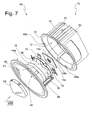
- a board 15 is mounted on the light source 13, a plurality of LEDs 14 a, 14 b, 14 c are arranged on a placement surface 20.
- the arrangement surface is the total area required for mounting or attaching the LEDs, which encompasses the envelope contours around all LEDs.
- the board 15 will - what in Fig. 7 not shown - bolted directly to the bottom of the trough-shaped housing 11, or fastened thereto in a suitable other way.
- Fig. 7 further shows an insert 16 having a central opening 19.
- the insert 16 is made of plastic and is also screwed to the bottom of the trough-shaped housing 11.
- the central opening 19 engages over the arrangement surface 20 for the LED's 14a, 14b, 14c, 14d.
- the element 16 is so far substantially annular.
- the element 16 On the side facing away from the board 15, the element 16 has a reflection surface 18. Their function will be explained in detail later.
- a diffuser film 39 is indicated. This has only a small wall thickness.
- the outer dimensions of the circular disk-shaped diffuser film substantially correspond to the dimensions of the light entry surface of the lens element 24, 32 described later.
- the diffuser sheet 39 may be made of plastic and have some surface roughness to soften the light emitted by the LEDs and to provide better mixing.
- the diffuser film 39 is not necessarily provided in the embodiments of the luminaire according to the invention, but can be arranged there within the scope of the invention.
- the lamp 10 according to the invention also has evidence Fig. 7 a substantially annular cover member 21 formed on. This comprises a radially outwardly projecting collar 30 which comes to rest in the mounted state on the collar 31 of the housing 11.
- the preferably also made of plastic cover 21 includes an axial shoulder 23 which surrounds a central opening 22.
- a lens element 24 or a lens element 32 can be used.
- Fig. 7 shows only one of several possible lens elements 24. This lens element 24 is in the embodiment of Fig. 7 formed rotationally symmetrical.
- fastening elements 45a, 45b are formed in the form of claw-like projections.
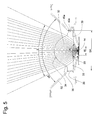
- the Axialabsatz 23 of the cover 21 has corresponding, in Fig. 7 not shown, and in Fig. 5 only very schematically indicated, fasteners 43 a, on, z. B. are formed as spring tabs, and with the claws 45a on the lens element 24, 32 in the sense of locking the two parts 24, 21 together, can work together.
- the lens element 24, 32 can therefore be used in the cover 21, and there are snapped or clipend locked.
- the annular body 21 thus forms a handling unit with the lens element 24, 32 inserted therein.
- This handling unit can, with the aid of further fastening elements 44a, 44b, which are arranged along the circumference of the cover element 21, be brought directly into engagement with corresponding counter-fastening elements 46a, 46b on the housing 11.
- the counter-fastening elements 46a, 46b may, for example, each be formed as a recess into which the fastening means 44a, 44b of the cover element 21 designed as spring tabs engage.
- the lamp 10 is fixed to the ceiling.
- the attachment of the lamp takes place in particular on a false ceiling, such that the Housing 11 is inserted with its cooling fins 17 through a circular opening in the false ceiling.
- spring clamping elements on the housings tension the collar 31 of the housing 11 with its back, so with his in Fig. 7 invisible side, against the inside of the housing space facing bottom of the plasterboard.
- the collar 30 of the cover element 21 projects out of the intended mounting opening for the luminaire and is visible.
- the collar 30 has an annular end surface 49 which defines a plane. The plane defined in this way is aligned parallel to the ceiling surface.
- a lens element 24 is provided which is rotationally symmetrical about its longitudinal central axis 26.
- the lens element 24 has a continuous plane light entry surface 27 and a continuous curved light exit surface 28.
- the light exit surface 28 is aspherically curved and substantially approximated to a parabola.
- That of the LED's, in particular of the LED 14 in Fig. 9 emitted light has a radiation angle ⁇ . This can for example be up to 180 °.
- the lens 24 is designed as a converging lens and reduces the emission angle to an angle ⁇ .
- the angle ⁇ is about 75 °.
- the lens element 24 is designed to be rotationally symmetrical as a whole, an opening angle of 75 ° with this luminaire is possible in this respect.
- the lens element 24 has an axial section 50 which has a constant cross-section with a circular cross-sectional area. In terms of its height, the axial section 50 essentially corresponds to the axial section 23 of the cover element 21.
- All embodiments have in common that a plurality of such fastening elements 45 along the circumference of the lens element, preferably arranged equidistant from each other, can be provided.
- the light emitted by the LEDs 14 or the group of LEDs initially strikes a diffuser film 39, which in the embodiment of FIG Fig. 9 can be optionally provided. As a result, a better light mixing is achieved.
- an element 16 which has a reflection surface 18.
- the efficiency of the lamp is increased by the reflection surface 18 so far.
- FIGS. 1 to 5 A further luminaire 10 according to the invention will now be described in which another lens element 32 is used.
- FIG. 2 This is in Fig. 2 shown in a single view in perspective view.
- the light entry surface 33 of the lens element 32 is formed identically as in the previously described lens element 24.
- the light entrance surface 33 is namely also formed plan and has a circular contour.
- the light exit surface 34 of this lens element 32 is formed differently.
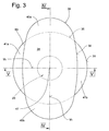
- FIG. 3 shows that the light exit surface 34 of the lens element 32 has transfer areas 40a, 40b, in which the lens element 32 projects beyond the peripheral contour 35 of the light entry surface 33.
- the lens element 32 shows so-called constriction regions 41 a, 41 b in which the light exit surface 34 in its contour 36 springs back relative to the contour 35 of the light entry surface 33.
- the central opening 22 of the cover 21 is circular in shape, and corresponds in size to the size of the light entry surface 33rd
- the crossing areas 40a, 40b thus also extend beyond the edges of the opening 22 to the outside.
- a continuously curved, almost circular boundary surface 34 in the form of the light exit surface 34 of the lens element 32 can be seen.
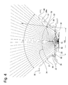
- the light beam emitted by the LEDs 14 at a beam angle ⁇ is very strongly collimated to an angular range ⁇ .
- sectional view of the Fig. 4 which shows a longitudinal section through the lens element 32 along the section line IV-IV, that as a result of the interface 34, a bundling of the light emitted by the LED 14 light on an angular range ⁇ .
- the angle ⁇ is greater than the angle ⁇ .
- the light emission angle ⁇ is approximately 50 ° and the light emission angle ⁇ is approximately 80 °.
- the angle ⁇ as the angle ⁇ may in particular be more than 20 °.
- Both embodiments of lens elements 24, 32 have in common that the cover 21 has a conical portion 52 with an opening angle ⁇ , which is about 90 °.
- the opening angle ⁇ is so far greater than the radiation angle of the lens element. This consideration applies regardless of the cross-sectional level.
- the cover 21 has so far no lighting function, but now serves to fade low stray light components.
- the light emission angle is determined exclusively by the boundary surfaces of the lens element 24, 32. Additional light-directing elements, in particular in the manner of conventional reflectors, are not provided in the luminaires according to the invention.
- the maximum width of the arrangement surface may be in the range of 10 to 30 mm.
- the outer diameter DA of the light entry surface is significantly larger, and is preferably more than 60 mm, for example about 100 mm.
- the light entry surface 27, 33 spans the entire arrangement surface 20 and exceeds its dimension W significantly, in particular by a multiple.
- the invention encompasses luminaires in which the outside diameter of the light entry surface is more than 1.5 times the dimension W of the arrangement surface.
- substantially all of the luminous flux emitted by the LEDs can be collected by the lens element 24, 32.
- the light entry surface 33, 27 of the lens element 24, 32 is flat and has no cavity or the like.
- the lens element 32, 24, which is also referred to as collimator optics in the context of this patent application, has no total reflection surfaces, which are usually present in lens elements of the prior art.
- the respective light entry surface 27, 33 of the lens element 24, 32 may also be provided with a certain roughening in order to achieve the same desired effect of a soft drawing of the light and of a light mixture.
- the diffuser element or alternatively the roughened light entry side 27, 33 of the lens element also prevents an immediate view of the light source 13.
- the angle of radiation or angle of a light distribution is referred to in particular as that angle, which is referred to in the expert sense as the opening angle, and represents the "full width half max" value. It is therefore the value of the light emission angle at which the light intensity has dropped to about half of the maximum light intensity.
Landscapes
- Engineering & Computer Science (AREA)
- General Engineering & Computer Science (AREA)
- Non-Portable Lighting Devices Or Systems Thereof (AREA)
- Securing Globes, Refractors, Reflectors Or The Like (AREA)
Applications Claiming Priority (1)
| Application Number | Priority Date | Filing Date | Title |
|---|---|---|---|
| DE102013021309.6A DE102013021309A1 (de) | 2013-12-19 | 2013-12-19 | Leuchte u.a. |
Publications (2)
| Publication Number | Publication Date |
|---|---|
| EP2886934A2 true EP2886934A2 (fr) | 2015-06-24 |
| EP2886934A3 EP2886934A3 (fr) | 2015-09-23 |
Family
ID=52282368
Family Applications (1)
| Application Number | Title | Priority Date | Filing Date |
|---|---|---|---|
| EP14004237.5A Withdrawn EP2886934A3 (fr) | 2013-12-19 | 2014-12-16 | Éclairage et autres |
Country Status (3)
| Country | Link |
|---|---|
| EP (1) | EP2886934A3 (fr) |
| CN (1) | CN104728690B (fr) |
| DE (1) | DE102013021309A1 (fr) |
Cited By (2)
| Publication number | Priority date | Publication date | Assignee | Title |
|---|---|---|---|---|
| US10180248B2 (en) | 2015-09-02 | 2019-01-15 | ProPhotonix Limited | LED lamp with sensing capabilities |
| DE102020122019A1 (de) | 2020-08-24 | 2022-02-24 | Oktalite Lichttechnik GmbH | Leuchte mit Linsenelement |
Families Citing this family (1)
| Publication number | Priority date | Publication date | Assignee | Title |
|---|---|---|---|---|
| CN106410539B (zh) * | 2015-07-28 | 2020-01-03 | 朗德万斯公司 | 电连接头和照明装置 |
Citations (5)
| Publication number | Priority date | Publication date | Assignee | Title |
|---|---|---|---|---|
| US20060091784A1 (en) * | 2004-10-29 | 2006-05-04 | Conner Arlie R | LED package with non-bonded optical element |
| JP2009003104A (ja) * | 2007-06-20 | 2009-01-08 | Shiizu:Kk | 照明レンズ及び照明装置 |
| WO2009030121A1 (fr) * | 2007-09-07 | 2009-03-12 | Xiaobing Hu | Lampe a del |
| DE102012006999A1 (de) | 2012-04-10 | 2013-10-10 | Erco Gmbh | Leuchte |
| DE102008027234B4 (de) * | 2008-06-06 | 2014-05-28 | Ifm Electronic Gmbh | Beleuchtungseinheit und Optikelement |
Family Cites Families (22)
| Publication number | Priority date | Publication date | Assignee | Title |
|---|---|---|---|---|
| US5285318A (en) * | 1992-06-22 | 1994-02-08 | Nioptics Corporation | Illumination system having an aspherical lens |
| JP2002304903A (ja) * | 2001-04-04 | 2002-10-18 | Matsushita Electric Works Ltd | 照明器具 |
| WO2008067515A1 (fr) * | 2006-11-30 | 2008-06-05 | Cree Led Lighting Solutions, Inc. | Luminaires, dispositifs d'éclairage et composants destinés à ceux-ci |
| US20080232110A1 (en) * | 2007-03-20 | 2008-09-25 | Ming-Tsai Wang | Illuminating device having enhanced light gathering effect |
| DE202007008258U1 (de) * | 2007-04-30 | 2007-10-31 | Lumitech Produktion Und Entwicklung Gmbh | LED-Leuchtmittel |
| JP2009048920A (ja) * | 2007-08-22 | 2009-03-05 | Tokai Kogaku Kk | 照明装置 |
| CN101846286A (zh) * | 2009-03-23 | 2010-09-29 | 玉晶光电股份有限公司 | Led照明用透镜 |
| CN101929651B (zh) * | 2009-05-25 | 2016-08-03 | Lg伊诺特有限公司 | 间隙构件、透镜以及具有间隙构件和透镜的照明装置 |
| KR101007134B1 (ko) * | 2009-06-05 | 2011-01-10 | 엘지이노텍 주식회사 | 조명 장치 |
| KR101028201B1 (ko) * | 2009-05-25 | 2011-04-11 | 엘지이노텍 주식회사 | 렌즈 및 이를 구비한 조명 유닛 |
| CN201535478U (zh) * | 2009-09-29 | 2010-07-28 | 东莞巨扬电器有限公司 | 一种led透镜 |
| DE102010004825A1 (de) * | 2010-01-15 | 2011-07-21 | Schott Ag, 55122 | Kollimierte Lichtquelle und Verfahren zu deren Herstellung |
| DE202010002676U1 (de) * | 2010-02-23 | 2011-07-26 | Zumtobel Lighting Gmbh | Einbauleuchte mit Basiskörper und domförmigem Reflektor |
| CN102859266A (zh) * | 2010-04-23 | 2013-01-02 | 皇家飞利浦电子股份有限公司 | 基于led的照明单元 |
| DE202011002138U1 (de) * | 2011-01-31 | 2011-04-21 | Franz Sill Gmbh | LED-Leuchte |
| JP2012174601A (ja) * | 2011-02-23 | 2012-09-10 | Mitsubishi Electric Corp | 照明装置 |
| DE102011107355A1 (de) * | 2011-06-29 | 2013-01-03 | Zett Optics Gmbh | Punktleuchte |
| US20130027929A1 (en) * | 2011-07-28 | 2013-01-31 | Mcmillan George Erik | Exchangeable Multi-Lensing System for Multi-Application LED Lighting |
| EP3367445B1 (fr) * | 2011-11-23 | 2020-07-29 | Quarkstar LLC | Dispositifs émettant de la lumière à propagation asymétrique |
| JP2013182670A (ja) * | 2012-02-29 | 2013-09-12 | Panasonic Corp | 照明器具 |
| DE202012004157U1 (de) * | 2012-04-10 | 2013-07-16 | Erco Gmbh | Leuchte |
| WO2013175564A1 (fr) * | 2012-05-22 | 2013-11-28 | 株式会社巽中央経營研究所 | Unité d'éclairage à rayonnement ovale |
-
2013
- 2013-12-19 DE DE102013021309.6A patent/DE102013021309A1/de not_active Ceased
-
2014
- 2014-12-16 EP EP14004237.5A patent/EP2886934A3/fr not_active Withdrawn
- 2014-12-19 CN CN201410858316.4A patent/CN104728690B/zh not_active Expired - Fee Related
Patent Citations (5)
| Publication number | Priority date | Publication date | Assignee | Title |
|---|---|---|---|---|
| US20060091784A1 (en) * | 2004-10-29 | 2006-05-04 | Conner Arlie R | LED package with non-bonded optical element |
| JP2009003104A (ja) * | 2007-06-20 | 2009-01-08 | Shiizu:Kk | 照明レンズ及び照明装置 |
| WO2009030121A1 (fr) * | 2007-09-07 | 2009-03-12 | Xiaobing Hu | Lampe a del |
| DE102008027234B4 (de) * | 2008-06-06 | 2014-05-28 | Ifm Electronic Gmbh | Beleuchtungseinheit und Optikelement |
| DE102012006999A1 (de) | 2012-04-10 | 2013-10-10 | Erco Gmbh | Leuchte |
Cited By (3)
| Publication number | Priority date | Publication date | Assignee | Title |
|---|---|---|---|---|
| US10180248B2 (en) | 2015-09-02 | 2019-01-15 | ProPhotonix Limited | LED lamp with sensing capabilities |
| DE102020122019A1 (de) | 2020-08-24 | 2022-02-24 | Oktalite Lichttechnik GmbH | Leuchte mit Linsenelement |
| DE102020122019B4 (de) | 2020-08-24 | 2024-05-08 | Oktalite Lichttechnik GmbH | Leuchte mit Linsenelement |
Also Published As
| Publication number | Publication date |
|---|---|
| EP2886934A3 (fr) | 2015-09-23 |
| CN104728690B (zh) | 2018-10-02 |
| CN104728690A (zh) | 2015-06-24 |
| DE102013021309A1 (de) | 2015-06-25 |
Similar Documents
| Publication | Publication Date | Title |
|---|---|---|
| EP2729838B1 (fr) | Élément optique | |
| EP2650597A2 (fr) | Eclairage | |
| DE102011078287A1 (de) | Lichtlenkungselement | |
| DE202010002676U1 (de) | Einbauleuchte mit Basiskörper und domförmigem Reflektor | |
| DE102020127476A1 (de) | Gebäudeleuchte | |
| DE102012102732A1 (de) | Leuchte mit Lichtabstrahlung in einen Randbereich | |
| DE102013021309A1 (de) | Leuchte u.a. | |
| EP3408584B1 (fr) | Appareil d'éclairage muni d'un élément de recouvrement pyramidal ou conique | |
| DE102013021308B4 (de) | Leuchte | |
| EP1837590A1 (fr) | Phares DEL et système d'éclairage doté de tels phares | |
| EP2650602B1 (fr) | Lampe avec LEDs et optiques de collimation | |
| AT509563B1 (de) | Leuchte mit lichtausrichtungselementen | |
| EP3408587B1 (fr) | Système optique destiné à influer sur l'émission de lumière d'une source de lumière | |
| EP3045803B1 (fr) | Éclairage | |
| DE102009049301A1 (de) | Leuchte | |
| DE102024126258B3 (de) | System von Leuchten zur Ausleuchtung einer Gebäudefläche, umfassend unterschiedliche Leuchten mit baugleichen Gehäusen und baugleichen Bündelungs-Optiken | |
| EP2940374B1 (fr) | Élément optique pour une source lumineuse d'un éclairage, et éclairage | |
| DE202012004157U1 (de) | Leuchte | |
| EP2647903B1 (fr) | Elément de lentille notamment pour module de lumière de secours | |
| EP4107426B1 (fr) | Lampe allongée | |
| EP2924346B1 (fr) | Optique pour un éclairage | |
| DE102012202121B4 (de) | Leuchte | |
| WO2025120185A1 (fr) | Double réflecteur à del | |
| DE202008017182U1 (de) | Leuchte | |
| DE102018119606A1 (de) | Optisches Element für eine Leuchte, insbesondere Büroleuchte, sowie Leuchte |
Legal Events
| Date | Code | Title | Description |
|---|---|---|---|
| PUAI | Public reference made under article 153(3) epc to a published international application that has entered the european phase |
Free format text: ORIGINAL CODE: 0009012 |
|
| 17P | Request for examination filed |
Effective date: 20141216 |
|
| AK | Designated contracting states |
Kind code of ref document: A2 Designated state(s): AL AT BE BG CH CY CZ DE DK EE ES FI FR GB GR HR HU IE IS IT LI LT LU LV MC MK MT NL NO PL PT RO RS SE SI SK SM TR |
|
| AX | Request for extension of the european patent |
Extension state: BA ME |
|
| PUAL | Search report despatched |
Free format text: ORIGINAL CODE: 0009013 |
|
| AK | Designated contracting states |
Kind code of ref document: A3 Designated state(s): AL AT BE BG CH CY CZ DE DK EE ES FI FR GB GR HR HU IE IS IT LI LT LU LV MC MK MT NL NO PL PT RO RS SE SI SK SM TR |
|
| AX | Request for extension of the european patent |
Extension state: BA ME |
|
| RIC1 | Information provided on ipc code assigned before grant |
Ipc: F21S 8/02 20060101AFI20150818BHEP Ipc: F21V 7/04 20060101ALN20150818BHEP Ipc: F21V 5/04 20060101ALI20150818BHEP Ipc: G02B 19/00 20060101ALN20150818BHEP Ipc: F21V 13/04 20060101ALN20150818BHEP Ipc: F21V 17/00 20060101ALN20150818BHEP Ipc: F21Y 101/02 20060101ALN20150818BHEP Ipc: F21V 5/08 20060101ALN20150818BHEP |
|
| R17P | Request for examination filed (corrected) |
Effective date: 20160323 |
|
| RBV | Designated contracting states (corrected) |
Designated state(s): AL AT BE BG CH CY CZ DE DK EE ES FI FR GB GR HR HU IE IS IT LI LT LU LV MC MK MT NL NO PL PT RO RS SE SI SK SM TR |
|
| 17Q | First examination report despatched |
Effective date: 20160531 |
|
| STAA | Information on the status of an ep patent application or granted ep patent |
Free format text: STATUS: EXAMINATION IS IN PROGRESS |
|
| GRAP | Despatch of communication of intention to grant a patent |
Free format text: ORIGINAL CODE: EPIDOSNIGR1 |
|
| STAA | Information on the status of an ep patent application or granted ep patent |
Free format text: STATUS: GRANT OF PATENT IS INTENDED |
|
| RIC1 | Information provided on ipc code assigned before grant |
Ipc: G02B 19/00 20060101ALN20221205BHEP Ipc: F21Y 115/10 20160101ALN20221205BHEP Ipc: F21V 17/00 20060101ALN20221205BHEP Ipc: F21V 13/04 20060101ALN20221205BHEP Ipc: F21V 7/04 20060101ALN20221205BHEP Ipc: F21V 5/08 20060101ALN20221205BHEP Ipc: F21V 5/04 20060101ALI20221205BHEP Ipc: F21S 8/02 20060101AFI20221205BHEP |
|
| INTG | Intention to grant announced |
Effective date: 20230104 |
|
| STAA | Information on the status of an ep patent application or granted ep patent |
Free format text: STATUS: THE APPLICATION IS DEEMED TO BE WITHDRAWN |
|
| 18D | Application deemed to be withdrawn |
Effective date: 20230516 |