EP2887005A1 - Système de bobine pour véhicule - Google Patents
Système de bobine pour véhicule Download PDFInfo
- Publication number
- EP2887005A1 EP2887005A1 EP14004051.0A EP14004051A EP2887005A1 EP 2887005 A1 EP2887005 A1 EP 2887005A1 EP 14004051 A EP14004051 A EP 14004051A EP 2887005 A1 EP2887005 A1 EP 2887005A1
- Authority
- EP
- European Patent Office
- Prior art keywords
- coil
- underwater
- air
- spindle
- winding
- Prior art date
- Legal status (The legal status is an assumption and is not a legal conclusion. Google has not performed a legal analysis and makes no representation as to the accuracy of the status listed.)
- Granted
Links
Images



Classifications
-
- F—MECHANICAL ENGINEERING; LIGHTING; HEATING; WEAPONS; BLASTING
- F42—AMMUNITION; BLASTING
- F42B—EXPLOSIVE CHARGES, e.g. FOR BLASTING, FIREWORKS, AMMUNITION
- F42B15/00—Self-propelled projectiles or missiles, e.g. rockets; Guided missiles
- F42B15/01—Arrangements thereon for guidance or control
- F42B15/04—Arrangements thereon for guidance or control using wire, e.g. for guiding ground-to-ground rockets
-
- F—MECHANICAL ENGINEERING; LIGHTING; HEATING; WEAPONS; BLASTING
- F42—AMMUNITION; BLASTING
- F42B—EXPLOSIVE CHARGES, e.g. FOR BLASTING, FIREWORKS, AMMUNITION
- F42B15/00—Self-propelled projectiles or missiles, e.g. rockets; Guided missiles
- F42B15/20—Missiles having a trajectory beginning below water surface
Definitions
- the invention relates to a coil system for a vehicle, in particular for a guided missile, comprising an underwater coil, which is prepared for a trigger in an underwater travel of the vehicle, an air coil, for a subsequent withdrawal in the air to a destination and for staying on Vehicle is prepared by then, and wound on both coils, continuous data conductor.
- a data conductor which is prepared as a data or signal transmission line for the transmission of signals. Because of the high transmission bandwidth and low signal attenuation at the same time, such data conductors are usually designed as optical waveguides.
- the data conductor is wound in a coil and connected to a spindle which carries the winding package. During travel or during the flight of the vehicle, the data conductor is unwound from the coil, so that the data connection between a transmitting or receiving station of the control center and the moving vehicle is maintained.
- the unwinding coil is usually arranged on or in the vehicle so that the unwound data conductor can remain as stationary as possible in the air or water space.
- the coil system comprises an underwater coil, which on the missile during the Unterwasserfahrt remains connected and handles the data conductor. After the emergence of the missile from the water, the underwater coil is dropped with a buoy and the data conductor is unwound from an air coil, which remains during the flight on the missile.
- the buoy which forms the transition between an underwater data conductor and an overhead data conductor, sinks onto the water surface on a parachute while the guided missile is approaching its destination.
- the invention is based on the consideration that the discharge of the underwater spool on the buoy is problematic.
- the data conductor should also be unwound during the descent of the buoy to the missile to compensate for the descent. This often leads to entanglement in the parachute or the buoy and thus a buckling of the data conductor, so that the signal transmission is disturbed or even interrupted.
- the data conductor which is unwound in the air, sinks to the buoy on the surface of the water, becomes tangled to the buoy and is also kinked or torn by waves. Similar or similar problems occur when trying to keep the buoy below the water surface to make it difficult to detect.
- the ejection resistant arrangement of the underwater spool on the air spool avoids these problems. Both coils remain on the vehicle and a buoy can be dispensed with.
- the data conductor is first unwound from the underwater coil and then from the air coil, wherein the line transition from the winding package of the underwater coil to the winding package of the air coil is expediently executed canister-free or buoy-free. Tangling in the buoy or a separated underwater coil can be prevented.
- the vehicle is prepared to be able to drive both in the water and in the air, while driving can also be understood as flying and / or diving.
- the vehicle may be a manned or unmanned missile and is conveniently provided with an underwater drive and / or an air drive or a drive that drives both under and over water the vehicle, such as a rocket engine.
- the air-core coil and the underwater coil are two coils, each with at least one separate winding package, which are preferably spaced apart from one another.
- the winding packages are preferably designed so that in a deduction first the winding package of the underwater coil - in particular completely - is unwound and then the winding package of the air-coil - in particular completely - is unwound - when the winding of the coil system is complete.
- the underwater bobbin is prepared for takeoff during underwater travel of the vehicle, particularly an underwater flight powered by a rocket engine.
- Such a preparation implies that the unwinding of the underwater bobbin, that is to say the withdrawal of the underwater bobbin, proceeds at this speed without kinking of the data conductor - and thus without data loss during normal signal transmission - and even more without a demolition of the data conductor, so that the signal transmission is error-free can be maintained.
- the air-core coil is prepared for extraction in the air to a destination. So it is located at the trigger in the air, firmly attached to a component of the vehicle. If the vehicle is a guided missile, then the trigger should go smoothly and reliably up to a maximum speed typical for the missile, for example, up to a speed of 250 m / s.
- the length of the data conductor should be at least five kilometers, in particular at least 20 kilometers.
- the underwater spool is fixed to the air-core coil. This implies that a release of the underwater spool from the air-core coil during normal operation is not provided and is also not possible in error-free operation.
- the underwater coil is expediently fixed to the air-core coil so that it can only be separated from the air-core coil on the ground and in particular only with tools.
- An ejection mechanism for an automated or manual ejection does not exist.
- the underwater spool is thus carried along to the destination during the drive of the vehicle, in particular during the flight of the guided missile. In other words, the underwater spool remains attached to the air-core spool even when the air-core spool is already being unwound, in particular at least half of it has already been unwound.
- the underwater coil is expediently attached at least partially behind the air-core coil.
- Such an arrangement is favorable, since the data conductor is expediently generally unwound first from the underwater coil and only then from the air-core coil, while the vehicle fulfills its mission.
- the direction here refers to the direction of travel of the vehicle or its construction, so that the rear is arranged behind the top of the vehicle.
- a spool consists at least of a spindle and at least one winding package and may optionally have a housing which at least partially shields the winding package from the outside.
- the winding package includes the wound data conductor in a plurality of turns.
- the spindle may be an external take-off spindle or an internal take-off spindle, the winding package being arranged radially outside the spindle in the case of an external withdrawal spindle, the data conductor thus being wound onto the spindle, and the winding package being arranged radially inside the spindle in the case of an internal withdrawal spindle.
- the data conductor is usually first wound as a winding package and this is then used in the internal withdrawal spindle, which surrounds the winding package radially outside and thus can also fulfill a housing function.
- the inner trigger spindle and the outer trigger spindle are also referred to below as the inner spindle and outer spindle.
- the data conductor expediently comprises a data line body, in particular a light pipe body, such as a glass body.
- the data line body may be surrounded by a shielding body, for example another glass body with a different refractive index, so that a reflecting plane is created within which the data-carrying radiation remains.
- a metallic shielding body is also possible.
- the data conductor also suitably comprises an outwardly protective sheath, for example in the form of a plastic coating, a textile sheath or a sheath with fibrous tissue.
- a stabilizing element may be arranged, for example a stable thread, which improves the data conductor with regard to its tensile strength.
- the data conductor is a continuous conductor, so it goes through from the beginning of the underwater coil to the end of the air coil, without opening into a receiving station, such as an amplifier or other electronic component. He may have a splice, for example, between the winding packages of the two coils, ie a connection point at which two previously separated data conductor parts are connected to one another in a signal-transmitting manner. Conveniently, however, the data conductor passes spliceless from one winding package to the other, in particular the data conductor is spliceless from the beginning of the underwater spool to the end of the air-core spool, so that the winding packages are also spliceless.
- the data conductor can be divided into an underwater conductor and an air conductor, wherein the underwater conductor expediently made thicker, for example, thicker jacketed is. As a result, a greater withdrawal resistance under water can be taken into account.
- a strict separation of the conductor types on the winding packages is not absolutely necessary, so that, for example, the thicker underwater data conductor can still be inserted into the winding package of the air-core coil and, for example, can form several layers of the air-core coil. This is particularly useful if there is the possibility that the data conductor is also unwound during an underwater ride of the air coil and thereby exposed to increased friction or withdrawal resistance.
- the two coils can form a system in which, for example, the spindles of the two coils directly adjacent to each other and are separated from each other, for example, only by a paragraph.
- a common, one-piece spindle for both coils is possible.
- the underwater spindle is expediently screwed or welded to the housing or the spindle of the air-core coil, so that a firm cohesion is ensured.
- Both coils can form an internal cavity through which an engine jet is guided during the flight of the missile.
- an engine beam guide can be guided transitionless through the two spindles.
- the spindle of the underwater spool is attached to a housing of the air-core coil.
- the underwater spindle may be internal spindle or external spindle, depending on the design of the underwater coil.
- the underwater spool can protrude from a housing of the air-core coil and, in particular, protrude from a housing of the missile.
- a housing of the air coil and the underwater coil at least partially surrounds housing and thus protects.
- the housing must In this case, it should not be made in one piece, wherein, however, an outer surface of the housing expediently also forms an outer surface of the vehicle or of the guided missile.
- the underwater coil is an internal withdrawal coil. With this configuration can be counteracted tangling in the settlement of the underwater coil under water, so in an underwater discharge.
- This aspect of the invention is based on the consideration that in an air outlet and also in an underwater extraction there is always the risk of multiple extraction, ie the simultaneous withdrawal of several turns, so that a free coil of wire is formed. This easily leads to a kinking of the conductor.
- the winding package is expediently designed to be backwards, ie towards the withdrawal direction, tapered, so that a sharp winding edge towards the rear is avoided as possible.
- a radially inwardly withdrawn data conductor has the much greater tendency to stand out from the underlying or radially outward Windungslagen.
- the trigger resistance is lower and thereby also the narrowest radius of the data conductor at the point of the momentary detachment of the data conductor from the winding package to the inside.
- an inner diameter of a discharge opening of the underwater coil is larger than an outer diameter of a discharge opening of the air coil to the rear.
- a further advantageous embodiment of the invention provides that a conductor transition is fixed in the form of a transition section of a winding package of the underwater coil to a winding package of the air coil on the winding package of the air coil.
- the fixation can be done for example by a bond or a fixation using a thread.
- bonding another, especially firmer bonding is useful, as such, with which the turns of the air coil are glued together.
- a conductor transition from a winding package of the underwater coil to a winding package of the air-core coil is guided at least partially transversely to the turns of the winding package of the air-core coil.
- This offers the Conductor transition the passing water a lower resistance, so that the conductor junction can be easily fixed.
- Under transverse here is an angle of at least 70 °, in particular a right angle to the turns of the winding package of the air coil to understand.
- the conductor transition at such locations which do not run across the turns, still provide a relatively high resistance to attack by the passing water. Due to the transverse laying, however, a firm fixation of the conductor transition on the air-core coil can be ensured over a relatively large distance, so that inadvertent detachment by the passing water is counteracted.
- a winding bottom of the at least one spindle of the underwater coil lies radially within a winding bottom of the at least one spindle of the air-core coil.
- a diameter of a separation aid or a steering means of the underwater coil is smaller than a diameter of the innermost layer of the at least one winding package of the air coil.
- the data conductor of the underwater coil can be unwound from the air-core coil.
- the diameter of the radially outermost layer of the at least one winding package of the underwater coil is smaller than the diameter of the innermost layer of the at least one winding package of the air-core coil.
- the underwater bobbin has a steering means which moves the withdrawing data conductor radially outward, for example the underlying layer of turns of the winding package or the winding bottom lifts.
- a steering means such means are suitable, which ensure that the data conductor at the point where it is released from a winding package, at least a little bit is lifted radially outward.
- the steering means such that it is a rear, radially projecting collar. This can, for example, stand directly from the winding bottom of the at least one spindle or from another element of the underwater coil or another unit.
- the collar may be a rear, tangentially encircling and radially outwardly directed formation and may be part of the underwater coil, for example. Possible, for example, a flange in the manner of steel construction.
- the steering means projects radially beyond the outermost turn of the at least one winding package of the underwater coil.
- the steering means lies completely radially within a winding bottom of the at least one spindle of the air-core coil, that is, nowhere radially projects beyond the winding bottom of the air-core coil.
- the axial position is independent of this. In this way it can be ensured that even if the data conductor is subtracted from the lowest layer of the at least one winding package of the air coil, prevents contact with the steering means in an air extraction and thus a trouble-free signal transmission is maintained by the data conductor.
- the steering means is chamfered to the winding package of the underwater coil.
- the slope is designed so that it forms an angle to the winding bottom of at least one spindle of the underwater coil greater than 120 ° or in other words, an angle between the radial direction and bevel of greater than 30 ° is formed.
- the bevel suitably extends as far as the winding bottom, wherein a small step in the height of a maximum of two winding layers is harmless in this case.
- the bevel may be a conical surface, which is expediently rounded radially outward in the profile. The data conductor can grind along the chamfer and round without bending or kinking with too small a radius.
- both coils are usually wet, as well as they dip into the water.
- the envelope of the data conductor for example in the case of a textile wrapping or wrapping with fibrous tissue, sucks up with water. This can lead to the fact that the thickness of the data conductor increases and thus a winding package of a coil builds up a certain pressure. While the windings readily withstand such pressure, the pressure for a transition portion of the data conductor from a winding package of the underwater spool to a winding package of the air-core spool may be problematic.
- the transition of the data conductor from a winding package of the underwater coil to a winding package of the air-core coil is inserted into a laying channel.
- the data conductor can be protected by the laying channel and prevented from buckling.
- the laying channel can be incorporated in the underwater spool, for example in a front or rear flange of the underwater spool.
- the laying channel is attached where the winding package of the underwater coil to an axial boundary surface, such as a flange, adjacent.
- the laying channel is guided to the radially upper end of the boundary surface, for example of the flange.
- the laying channel extends to the winding base, so that the data conductor can be inserted from the bottom layer directly into the laying channel.
- the direction of the laying channel has a tangential component in order to allow a smooth directional transition to the tangential winding direction of the data conductor on the winding base.
- the orientation of the laying channel is inclined by a maximum of 30 °, in particular a maximum of 15 °, for aligning the winding base at the place where the laying channel reaches the winding base.
- the laying channel can advantageously be designed to be at least substantially rectilinear or curved.
- a further advantageous embodiment of the invention provides that the underwater coil is arranged relative to the air-core coil, that the data conductor is withdrawn in a regular deduction from the air-core coil radially inside a spindle of the underwater coil and designed as an outer spindle.
- the underwater coil thus forms an inner opening through which the data conductor is guided.
- the at least one winding package of the underwater coil is arranged partially behind the at least one winding package of the air-core coil.
- the winding bottom of the at least one spindle of the underwater coil is located radially outside the winding bottom of the at least one spindle of the air coil, the circumference of the winding bottom of the underwater coil is thus greater than the circumference of the winding bottom of the air coil.
- the winding bottom of the underwater coil can here be arranged completely or partially behind the winding bottom of the air-core coil.
- a compact and mechanically stable design of the winding system can be achieved if the at least one spindle of the underwater coil is fastened to a housing of the air-core coil. A holding power flow between the coils thus passes through the housing.
- the air-core coil and the at least one spindle of the underwater spool there may be an air space through which the air-drawn off from the air-core coil Data conductor is passed. Such a vent air space separates the two spindles of the two coils.
- the at least one spindle of the underwater coil forms a housing portion of the air coil.
- This housing section is expediently brought together conically to the rear, so that therefore reduces the inner diameter of the housing to the inside, the spindle thus forms a part of the rearwardly tapered housing.
- the spindle may be multi-layered, so that the material of the housing is different from the material of the winding bottom of the spindle of the underwater coil.
- a large winding package volume and thus a long data conductor in the underwater coil can be achieved if the winding bottom of the at least one spindle of the underwater coil is located radially further outside than at least inner parts of the at least one winding package of the air coil.
- the data conductor When the data conductor is removed from the underwater spool and the air-core coil, the data conductor is subjected to a great load because of the high take-off speeds.
- the withdrawn data conductor forms waves which contribute to an increase in the load.
- the data conductor in a transition region or transition section from a winding package of the underwater coil to a winding package of the air coil in a recess which may be embodied for example in the form of a groove and hereinafter referred to as laying channel, is guided.
- the recess or laying channel may be arranged at the rear end of the underwater coil, for example in a rear steering means of the underwater coil, which may be designed as a flange or generally as a radial projection on the winding bottom.
- the laying channel is expediently up to a radially upper end of the Guided means and is located on the winding package facing side of the steering means.
- the laying channel has a first winding section facing the groove section and a second rearwardly facing groove section. Both sections can be arranged in the steering means.
- the data conductor is expediently laid in both sections.
- a particularly strong deduction load of the data conductor can be avoided if the laying hole pierces a steering means in the rear part of the underwater coil in the region of the largest radial extent of the steering means as in a valley.
- the data conductor removed from the laying channel does not form a wave as large as without the laying channel.
- the laying channel should cut deeply into the steering means. It is advantageous if the radial elevation of the valley bottom exceeds a maximum of 30% of the elevation of the steering means over the winding bottom of the at least one spindle of the underwater coil over the winding bottom.
- the bottom of the valley can also be located radially lower than the spindle bottom or winding bottom of the underwater coil.
- the edge along the circumference should therefore be as even as possible. This can be achieved if a circular extending outer edge of the steering means is notched by the laying - from rear to front on the steering means - radially maximally 20% of the collection of the steering means on the spindle bottom of the underwater coil, suitably not more than 5 mm, in particular maximum 2 mm.
- a discontinuity in the course of the data conductor can lead to a wave during the deduction and thus to an increased deduction load of the data conductor.
- the base of the laying channel is radially curved at its rear end in such a way that the data conductor is guided radially kink-free in the laying channel and also radially kink-free emerges from it.
- the data conductor will deflect slightly in the tangential direction due to the change in direction of the trigger point. In order to avoid a bumping of the data conductor at an edge of the rear region of the laying channel, it is premature if the rearwardly facing groove portion of the laying channel terminates in the tangential withdrawal direction of the data conductor axially to the rear.
- a uniform course of the data conductor connected to a smooth outer edge of the steering means can be achieved when the winding package of the underwater coil facing groove portion is oriented at an angle of at least 75 ° to the axial direction of the coil system, and if possible over most of its total length, in particular over the entire length of the front region or groove portion of the laying channel.
- the data conductor is wound up between the underwater spool and the air-core spool on an intermediate spool.
- the intermediate coil may have an intermediate winding consisting of only one layer.
- the intermediate winding on the intermediate coil is expediently arranged completely radially inside the winding bottom of the at least one spindle of the air-core coil.
- the intermediate coil is provided on a front flange with a laying channel in which the data conductor is laid.
- the invention is directed to a vehicle, in particular a guided missile with a rocket engine, with a coil system arranged at the rear, in particular as described above. It is proposed that an underwater coil of the coil system prepared for withdrawal of a data conductor during underwater travel of the vehicle be attached to the rear end of the coil. Conveniently, the coil system is arranged at the rear of the vehicle and in particular about an engine jet space.
- the underwater coil expediently comprises at least one spindle and at least one winding package.
- the invention is directed to a method for maintaining a data connection between a moving vehicle, in particular a flying missile, and a control center, in particular a launching station, via a data conductor in which the data conductor is withdrawn from an underwater coil during underwater travel of the vehicle, the vehicle enters the air through the water surface and the data conductor is withdrawn from an air coil during an overwater journey.
- the control center can be in a building or a vehicle, for example in a submarine.
- the underwater spool preferably remains firmly connected to the air-core coil during submarine and surface navigation to a destination of the vehicle. It can be dispensed with the dropping of an interface, such as a buoy, whereby a tangling of the data conductor can be prevented.
- the air extraction is expediently until the vehicle reaches a predetermined destination, for example after a flight phase.
- a portion of the underwater coil is still withdrawn in the air.
- the invention is directed to a method for winding a coil system with a data conductor, which is designed to hold a data connection between a moving vehicle, in particular a flying missile, and a control center, wherein the data conductor first on a spindle of an air coil and then on a spindle of an underwater spool of the spool system is wound.
- both coils must be wound with a continuous data conductor.
- the spindle of the underwater coil according to the invention is held during winding in a position in which between its and the spindle of the air coil, a discharge opening for outputting the data conductor in a withdrawal from the air coil is present.
- the spindle of the underwater spool is held in its winding position by an auxiliary holder during winding, wherein the auxiliary holder is removed after winding and the spindle is then fixed ready for operation on the air-core coil.
- the spindle can be attached directly or advantageously indirectly, in particular via a housing of the vehicle to the air coil.
- the two coils expediently remain immovable to each other during attachment.
- a third element is attached to the underwater spool and the air-core coil for attachment to each other.
- this third element is a housing of the vehicle.
- the air coil is attached directly to the housing of the vehicle. But it is also possible, the air coil expediently indirectly, so to attach via one or more other elements to the housing of the vehicle.
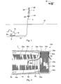
- FIG. 1 shows a vehicle 2, which is designed in this embodiment as a missile with a rocket engine.
- the guided missile is connected via a data conductor 4 with a control center 6, in this embodiment, a submarine.
- the data conductor 4 is a lead with a glass fiber core for transmitting optical signals, which is covered by a plastic sheath.
- the guided missile was launched from a torpedo tube of the submarine, which forms a launching station 8 for the guided missile.
- the missile has under a water surface 10, an emission-dependent route 12, for example, 400 m, covered.
- the guided missile After covering the underwater route 12, the guided missile has changed its direction of travel, piercing the water surface 10 and now continues its journey above the water surface 10 in the direction of a destination 14.
- the destination is, for example, 25 km away from the control center 6, the majority of this distance being covered by the vehicle 2 in the air.
- the data conductor 4 is mounted in the submarine at an interface 16 and connected via a further data connection signal technology with a control unit 18 of the control center 6.
- the control unit 18 controls a flight of the vehicle 2 both under water and over water and processes image data generated by a seeker head 20 of the vehicle 2, which the seeker head 20 picks up during the flight.
- the control unit 18 is signal-technically connected via the data conductor 4 to a control unit 22 which is disposed within the vehicle 2.
- This control unit 22 controls the flight of the vehicle 2 via rudder 24, wherein the control commands are transmitted from the control center 6 via the data conductor 4 to the control unit 22.
- the data of the seeker 20 are in turn transmitted via the data conductor 4 to the control center 6, which generates the control commands therefrom.
- the interface 16 has a coil, not shown, for outputting the data conductor 4 in order to be able to compensate for a movement of the control station 6 relative to the surrounding water without the data conductor 4 being pulled through the water.
- a coil system 26 which is arranged at the rear of the vehicle 2 and in FIG. 2 is shown in more detail.
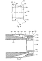
- FIG. 2 shows the rear part of the coil system 26 of the vehicle 2 FIG. 1 in a longitudinal section.
- the coil system is provided with the reference numeral 26a.
- similar components with the same reference number but depending on the embodiment with other reference letters are marked, if the components have slight differences, eg in size, position and / or function. If the reference number alone is mentioned without a reference letter, then the corresponding components of all embodiments are addressed.
- the coil system 26a comprises an air coil 28a and an underwater coil 30a, which in this embodiment is arranged completely behind the air coil 28a. While the air-core coil 28a is designed as an outer withdrawal coil, the underwater coil 30a is designed as an inner withdrawal coil.
- the data conductor 4 is wound both on the air coil 28a and on the underwater spool 30a and is continuous, in particular spliceless, on both spools 28a, 30a continuously.
- the air-core coil 28a comprises a spindle 32a on which the data conductor 4 is wound up layer by layer.
- the underwater spool 30 is also equipped with a spindle 34a, which, however, in this exemplary embodiment is designed as an internal spindle, ie a spindle which radially surrounds the winding package 36a of the underwater spool 30a formed by the layers or windings of the data conductor 4 from the outside.
- the spindle 32a of the air-core coil 28a is disposed radially inside the winding package 38a of the air-core coil 28a.
- the data conductor 4 is divided into three sections:
- the winding package 36a forms an underwater section 40 of the data conductor 4, which begins at the interface 16 of the control station 6, extends to the winding package 36a and forms this.
- a transition section 42a connects the winding package 36a to the winding package 38a of the air-core coil 28a.
- An air section 44 of the data conductor 4 forms the winding package 38a and extends to the control unit 22.
- the transition section 42a may also form a few turns of the air-core coil 28a. All three sections 40, 42a, 44 are traversed by a single, continuous optical waveguide which is guided without splicing through the three sections 40, 42a, 44. Only the casing of the data conductor 4 varies in the sections 40, 42a, 44.
- the casing is made thicker in the sections 40, 42a than in the air section 44.
- the data conductor 4 is more resistant to tearing in these two rear sections 40, 42a than in the air section 44
- the air section 44 can be withdrawn faster by its comparatively slimmer and lighter design, which is particularly advantageous for the air vent.
- the trigger of the data conductor 4 after piercing the water surface 10 is considerably accelerated, since the missile misses 14 speeds during its flight to the target 250 m / s reached.
- the underwater spool 30a remains with its spindle 34a - except for the unwound part of the data conductor 4 - on the vehicle 2.
- the spindle 34a is firmly connected to the other components of the vehicle 2, in this embodiment, with the outer housing 48a of the guided missile 2, which also at the same time forms the housing 48a of the air-core coil 28a.
- the spindle 34 is bolted to the housing 48 a and thus not detachable during the flight of the missile. It can be separated only after removal of the winding package 36a by means of tools from the rest of the vehicle 2, which is not provided in regular operation.
- the underwater spool 30a or its spindle 34 is welded to the vehicle 2.
- the underwater spool 30 or its spindle 34a is formed with a steering means 50a in the form of a flange is integrally connected to the winding bottom 52a of the spindle 34a.
- the data conductor 4 drags over the rounded edge 54a of the flange 50a and is thereby lifted off obliquely radially inward from the underlying winding layer.
- the steering means 50a is in this case designed as a radially inwardly pointing shape, which in this case projects further inward than the furthest inner winding layer of the winding package 36a of the underwater spool 30a, so that even the radially innermost layer of the data conductor 4 in the trigger still a bit far is pulled inwards.
- the radius of the steering means 50a at the narrowest point, ie at the edge 54a should be greater than the outer radius of the output opening 60a, so that the data conductor 4 unwinding from the air-core coil 28 does not abut the edge 54a.
- Particularly suitable is a radius which is at least 1.1 times the outer radius of the discharge opening 60a.
- this steering means 50a causes the winding package 36a does not have to be radially thinner towards the rear to avoid multiple deductions.
- the steering means 50a limits the winding package 36a to the rear so that an unwanted multiple deduction is thereby avoided by itself.
- the winding package 36a at least substantially unrestrictedly adjoins the steering means 50a.
- the interior 56 When immersed in the water, the interior 56 is flooded around the air coil 28a or within the housing 48a with water flowing through openings 58 in this interior 56. The water flows backwards and out through a discharge opening 60a out of the housing 48a of the air-core coil 28a. The flowing water pulls on the turns of the winding package 38a of the air-core coil 28a.
- the data conductor 4 is glued within the winding packages 36a, 38a, the individual turns of the data conductor 4 are thus glued together, so that a stable winding package 36a, 38a is formed.
- the bond is chosen so that the data conductor 4 is not bent too much in a deduction, so as not to jeopardize the data transfer.
- the bond is so strong that the corresponding winding package 36a, 38a sufficiently holds together even under water and not a multiple deduction arises by loose turns.
- transition portion 42a is a little way out through the air, so that the flowing water at this portion 42a tears more.
- part of the transition section 42a is glued to the underlying turns 62 of the air-core coil 28a more firmly than the turns 62 are interconnected are glued.
- an adhesive is used, which allows a detachment of the bonded data conductor 4 at a fast removal rate with a lower force than with a slower removal rate.
- the adhesive may be a silicone joined between turns 62 and transition section 42a.
- a part of the transitional portion 42a is transversely, namely perpendicular to the winding direction of the windings 62, guided to achieve the longest Verkleerbrecke.
- the transition section 42a still extends a little way into the winding package 38a of the air-core coil 28a and forms part of the uppermost layer of the windings of the air-core coil 28a. This makes it possible that the air coil 28a as far as the transition portion 42a ranges can be withdrawn under water without the data conductor 4 is impaired. What has been said about the transition section 42a is also applicable to the transition sections 42b and 42c.
- the air coil 28a is an outer coil including a plurality of winding layers extending parallel to the spindle bottom or winding bottom 64a. They form the winding package 38a, which is wound to the rear tapered to avoid unwanted multiple deduction of back turns.
- the vehicle 2 When the vehicle 2 is being driven, it is first fired from the launching station, wherein the data conductor is essentially unwound from the underwater spool 30a, but also somewhat from the spool of the interface 16. The unwinding takes place here by the tensile force exerted by the moving vehicle 2 on the data conductor 4, so that it unwinds by itself.
- the length of the underwater section 40 of the data conductor 4 is dimensioned so that the specified distance 12 under water is ⁇ 30 m longer or shorter than the length of the underwater section 40.
- the underwater coil is thus at least substantially completely unwound. If, when surfacing, the data conductor 4 is still on the underwater spool 30a, it will become in unwound at the longest first 30 m above water, in which the vehicle 2 is not yet so fast that the settlement or the deduction of the underwater spool 30a would be problematic.
- FIG. 3 shows another coil system 26b with an air coil 28b and an underwater coil 30b.
- the description of the following exemplary embodiments is essentially limited to the differences from the exemplary embodiment in FIG. 2 which is referred to with regard to features and functions that remain the same.
- Substantially identical components are basically numbered with the same reference numerals, and features not mentioned are adopted in the following exemplary embodiments without being described again.
- the underwater spool 30b is an outer take-off spool. It is arranged substantially outside the housing 48b, which, like the openings 58, the same as in the embodiment of FIG. 2 can be designed.
- the winding package 36b of the underwater spool 30b like the winding package 36a of the underwater spool 30a, is wound in a plurality of layers, but in the embodiment FIG. 3 from inside to outside, so that the data conductor 4 is unwound from outside to inside.
- the spindle 34b of the underwater spool 30b is directly connected to the spindle 32b of the air-core coil 28b, or both spindles 32b, 34b are integrally connected to each other so that at least their winding bottoms 64b, 52b are in one piece.
- the spindles 32b, 34b may be made of metal or for special applications of plastic.
- Both coils 28b, 30b are designed as hollow coils and hold a tubular cavity 68 (FIG. FIG. 4 ), so that the Gasleitrohr the missile or its rocket engine can lie in the missile axis. The engine jet is thus passed through the coils 28b, 30b.
- the underwater spool 30b is designed with a steering means 50b at its rear end. This is all round radially over the entire circumference on the outermost layer of the winding package 36b out, as in FIG. 3 , which indicates the winding package 36b by dashed lines, is shown.
- the steering means 50b causes the winding package 36b is also enclosed to the rear, so that the rear windings can not leave the winding package 36b in an unwanted multiple deduction and the data conductor 4 tangled.
- the entire winding package 36b of the underwater spool 30b is arranged radially inside the winding package 38b of the air-core spool 28b.
- the radially outermost layer of the winding package 36b is thus arranged radially within the radially innermost layer of the winding package 38b.
- the steering means 50b is dimensioned in its radial extent so that it does not protrude radially further than the winding bottom 64b of the air-core coil 28b. This ensures that the data conductor 4 drawn off from the air-core coil 28b does not abut on the underwater spool 30b and in particular on its steering means 50b.
- an outer diameter d of the steering means 50b of d (0.8 ⁇ 0.1) D has proved successful, where D is the diameter of the winding bottom 64b of the air-core coil 28b.
- the steering means 50b protrude somewhat beyond the winding bottom 64, but remain at least 3 mm radially within the outer circumference of the discharge opening 60b everywhere.
- the data conductor 4 is torn to the outside by the rotating trigger and the centrifugal forces acting in the process and rests against the rounded inner edge of the housing 48 in the region of the discharge opening 60b. If this inner edge is sufficiently far away from the winding bottom 64b, the data conductor 4 is therefore also led around at an edge 54b projecting radially somewhat beyond the winding bottom 64b or the steering means 50b of the underwater coil 30b.
- the spindle 34b of the underwater spool 30b is in FIG. 4 shown in a perspective view.
- FIG. 5 shows the spindle 34b in a side view.
- the winding bottom 52b is disposed between a front flange 66b and the rear flange-configured steering means 50b, so that the winding package 36b is held between these two flanges 50b, 66b.
- a not directly deducted turn of the winding package 36b is thus - even if they should slip axially - caught between the two flanges 50b, 66b.
- a drop of the winding package 36b or multiple deduction is not possible.
- the winding to the package 36 b facing flange is inclined to the radial direction by the angle ⁇ .
- This angle reduces the bending radius of the drawn over the edge 54b data conductor, so that the data transmission takes place even with a very busy data conductor 4 without interference.
- the greater the maximum speed of the vehicle under water the larger the angle ⁇ should be.
- the invention is generally also directed to a system of at least two vessels having a different design maximum speed under water.
- the vehicles are each equipped with a coil system according to the invention, wherein the angle ⁇ of the inclination of the rear steering means 50b to the radial direction in the vehicle with the higher maximum speed is greater than in the vehicle with the lower maximum speed.
- the winding package 36b is guided directly forward to the rear wall of the flange 66b, so it is applied to this.
- the trailing edge of the front flange 66b may be perpendicular to the winding bottom 52b, resulting in a large winding space.
- the data conductor 4 is led from the radially innermost layer of the winding package 36b radially outward to the air-core coil 28b, so it has to be led up between the winding package 36b and the flange 66b.
- winding package 36b If the winding package 36b now swells as a result of the wetting with water, it exerts a pressure on the rear wall of the flange 66b and thus squeezes the data conductor 4 between the winding package 36b and the flange 66b. This can lead to buckling of the data conductor 4, in particular in the radially inner region.
- the flange 66b delimiting the winding package 36b towards the front is designed with a laying groove 70b.
- This is incorporated as a depression in the rearwardly facing surface of the flange 66b and extends radially inward to the winding bottom 52b.
- the laying channel 70b is provided in its orientation with a tangential component, so that the data conductor 4 can be guided with a sufficiently large radius taut from the winding bottom 52b through the laying groove 70b radially outward.
- the laying channel 70b, with its radially outwardly facing surface ends shortly before the winding bottom 52b in a rounding 72 and predefines the curvature of the data conductor 4 routed along the rounding 72.
- the laying channel 70b has the depth of at least 0.8 of the diameter of the data conductor 4 in the transition section 42a. So that the underwater section 40 of the data conductor 4 extending transversely to the laying channel 70b is not bent over the edges of the laying channel 70b in the winding package 36b, the width of the laying channel 70b should also be small. It should be at most five times the diameter of the data conductor 4 in the transition section 42a, in particular only the maximum two times. Particularly advantageous is a ratio of the groove width to the data line diameter between 1 and 2, in particular between 1.2 and 1.6.
- the underwater spool 30a of the spool system 26a is equipped with a laying channel.
- This can be carried out exactly as the laying channel 70b FIG. 4 , Wherein it may be incorporated into the front flange of the spindle 34a and, depending on the embodiment, also in the housing 48a, as in the embodiment of FIG. 2 would be useful.
- the laying channel would be incorporated in the component, which connects directly to the winding package 36a and this limits to the front.
- FIG. 6 Another embodiment of a coil system 26c is shown in FIG FIG. 6 shown.
- the coil system 26c again has an air coil 28c and an underwater coil 30c.
- the air-core coil 28c may again be designed the same as the previous air-core coils 28a, 28b, with the exception of the housing 48c.
- the underwater coil 30c is designed as an outer coil, but radially outside the winding bottom 64c of the Air coil 28c arranged. In this case, the winding bottom 52c and thus also the entire winding package 36c of the underwater coil 30c are arranged radially outside the winding bottom 64c of the air-core coil 28c.
- the unwinding at a deduction data conductor 4 is performed during the deduction of the air coil 28c radially inwardly through the spindle 34c of the underwater bobbin 30c and is the trigger on the inside of the spindle 34c and that on the winding package 36c opposite side of the spindle 34c.
- the spindle 34c of the underwater spool 30c forms a part of the housing 48c of the air-core coil 28c, on the inner surface of which the unwinding data conductor 4 is guided while being pulled through the dispensing opening 60c.
- the housing 48c is a member surrounding the air-core coil 28c radially outward and completely enclosing it in the radially outward direction.
- the spindle 34c of the underwater spool 30c surrounds the air-core spool 28c at its rear end, thus forming part of the housing 48c.
- the spindle 34c is directly attached to a housing body of the housing 48c, and the housing 48c is also radially guided over the underwater spool 30c for protection against external influences.
- the housing 48c is thus divided in the region of the spindle 34c into two parallel sections, which overlap radially:
- the inner parallel part forms the housing inner wall in the region of the discharge opening 60c and the spindle 34c.
- the outer portion forms the vehicle body and a radial overlap of the underwater spool 30c for protection to the outside.
- the coil bottom 52c of the underwater coil 30c is located radially outward of the coil bottom 64c of the air coil 28c along its entire surface so that the diameter of the coil package 36c of the underwater coil 30c is larger than at least the inner turns of the coil package 38c of the air coil 28c.
- a large winding volume and thus a large length of data conductor 4 can be accommodated in a relatively small axial space.
- the data conductor 4 moving out of the discharge opening 74 can be kept radially spaced from a cavity 68c, through which an engine jet is guided to propel the vehicle 2 while the vehicle 2 is traveling.
- the underwater spool 30c is arranged with respect to the discharge port 60c so that its spindle 34c is axially in the vicinity of the narrowest point of the discharge port 60c.
- the overall design is very compact.
- the spindle inner surface forms the outer wall of the discharge opening 60c at its narrowest cross section.
- the underwater spool 30c is partially disposed axially behind the air-core coil 28c, so at least portions of the underwater spool 30c are disposed axially behind the air-core spool 28c.
- FIG. 7 shows the rear part of the vehicle 2, wherein the representation of the rudder 24 from FIG. 1 has been omitted for clarity.
- the rear part of the housing 48c with the underwater coil 30c arranged therein can be seen.
- Their discharge opening 74 forms the radially outermost region within the housing 48c of the rear of the vehicle 2.
- FIG. 7 It is clearly good to see that the large radius of the underwater bobbin 30c allows a long data line 4 on the underwater bobbin 30c with a relatively flat construction of the winding package 36c of the underwater bobbin 30c.
- FIG. 7 Within the discharge opening 74 is in FIG. 7 to see the back of the spindle 34c of the underwater spool 30c and a spindle 76 of an intermediate spool 78 disposed radially inside the underwater spool 30c. Not shown is the winding package 36c of the underwater spool 30c and an intermediate winding 80, which in FIG. 6 indicated by dashed lines.
- the cavity 68c located radially inside the intermediate coil 78 forms the passage for the engine jet of the vehicle during its flight.
- FIG. 8 shows a perspective view of the vehicle 2 from the rear, looking forward in the direction of flight of the vehicle 2, again being dispensed with the representation of the rudder 24. Visible - from the outside inwards - is the housing 48c, the spindle 34c of the underwater spool 30c, the discharge opening 60c, the winding package 38c of the air-core spool 28c in front of the spool 76 of the intermediate spool 78, and the cavity 68 through which the jet of the engine during the flight of the Vehicle 2 exits. Also shown is the transition section 42 c of the data conductor 4, in the transition region from the underwater coil 30 c to the intermediate coil 78.
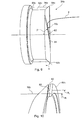
- the spindle 34c of the underwater spool 30c is in FIG. 9 shown in a perspective side view without the housing 48c. It can be seen the winding bottom 52c, the front flange 66c, which limits the only indicated winding package 36c of the underwater bobbin 30c forward, and the rear steering means 50c, which limits the winding package 36c to the rear. How to FIG. 5 described, the steering means 50c widens on its side facing the winding package 36c conically rearwardly with the cone angle ⁇ .
- a laying groove 70c is introduced, which has a front groove portion 82 and a rear groove portion 84.
- the front groove portion 82 is cut into the tapered and forwardly facing inclined surface of the steering means 50c, whereas the rear groove portion 84 is machined in the rearward facing surface of the steering means 50c.
- the laying channel 70c is arranged at the rear end of the winding package 36c, ie in the steering means 50c.
- the data conductor 4 is guided by the winding bottom 52c through the front groove portion 82 of the laying groove 70c and from there into the rear groove portion 84 of the laying groove 70c, to then be in a straight line to the intermediate winding 80, as in FIG. 8 is shown. He dives in this case by the steering means 50c, without being guided by this particularly far radially outward, whereby a wave formation of the data conductor 4 can be kept low in its deduction and thus hitting the data conductor 4 and its load during the deduction.
- FIG. 9 is implied as the data manager FIG. 4 is pulled straight out of the front groove portion 82 of the laying channel 70c during an overflow.
- the notch of the front groove portion 82 in the steering means 50c is in FIG. 10 especially good to see.
- the valley bottom 86 is deeply cut in the steering means 50c and protrudes in the region of its maximum radial extent only slightly beyond the radial extent or the radius R 1 of the winding bottom 52c addition.
- the maximum radial elevation of the valley bottom 86 or its maximum radius R 2 protrudes less than 50% of the elevation of the steering means 50c, in particular less than 1/3 of the elevation of the steering means 50c beyond the coil bottom 52c, both radii R 1 , R 2 being measured from the axis of symmetry of the coil system 26c and the spindle 34c, respectively. In this way, an extension of the data conductor 4, which may be present by the overcoming of the steering means 50c, be kept low, whereby a wave formation in the trigger is reduced.
- FIG. 11 shows a section of the spindle 34c of the underwater spool 30c from behind on the steering means 50c.
- the in FIG. 11 covered valley bottom 86 is shown in a narrow dashed line. Dashed lines the winding bottom 52c is shown.
- the valley bottom 86 protrudes only slightly radially beyond the spindle base 52c.
- the bottom of the valley 86 is also radially curved at its output side or rear end in such a way that the data conductor 4 is guided radially kink free both in the front groove portion 82 and in the rear groove portion 84 of the laying groove 70c, as well as out of the laying groove 70c, as in FIG. 11 is shown. Also in this way, a wave formation and a load of the data conductor 4 can be reduced in a bend to be avoided.
- the data conductor 4 drags during its withdrawal over the radially outermost edge 54c of the steering means 50c and the underwater spool 30c.
- This edge 54c is notched in the region of the laying channel 70c and thus impedes a deduction of the data conductor 4, since it grinds over this notch with each revolution.
- the circular outer edge 54c of the steering means 50c is scored only extremely slightly by the laying channel 70c, as viewed from the rear to the front of the steering means 50c FIG. 11 is shown. A small notch 88 still remains and is in FIG. 11 shown.
- the depth of the notch 88 is less than 10% of the elevation of the steering means 50c beyond the coil bottom 52c of the underwater coil 30c.
- the rear groove portion 84 of the laying channel 70c runs in the tangential withdrawal direction of the data conductor 4 axially to the rear out.
- the laying channel 70c in its rear groove portion 84 in principle loses its groove shape and is configured to a wedge-shaped depression pointing with the wedge tip in the withdrawal direction.
- the deducted from the laying channel 70c data conductor 4 can thereby freely swing out of the rear groove portion 84 out without abutting against an edge.
- the rearwardly facing groove portion 84 is designed with a significantly larger tangential width than the forwardly facing groove portion 82 has an axial width.
- the tangential width of the laying channel 70c in the rear region 84 is at least ten times the diameter of the data line 4 in the region of the transitional section 42.
- the orientation of the front groove section 82 should have a tangential component.
- the tangential component can be understood as a directional component of the front groove portion 82 in the tangential direction in a side view of the steering means 50c perpendicularly from above, as in FIG. 9 shown.
- the angle ⁇ between the axial direction of the coil system 26c and the orientation of the front groove portion 82 at least 45 °, in particular at least 60 °, with at least 75 ° have proven to be particularly advantageous.
- the laying channel 70c is covered at least partially, in particular in the front groove section 82. This can be done by a tear-off foil or another element. It is additionally or alternatively possible, at least partially fill the laying groove 70c and the front groove portion 82 of her with a silicone or other material.
- the data conductor 4 is guided inside through the underwater coil 30c to the front to the air coil 28c. So it runs with its transition portion 42c in the unwound state of the winding package 36c of the underwater coil 30c to the rear and through the rear edge 54c therethrough radially inward. In the further course, it is led forward again to reach through the discharge opening 60c through the winding package 36c of the air coil 28c.
- the transitional portion 42c may be wound on the intermediate spool 78.
- the intermediate coil 78 contains only a single layer, so that the data conductor 4 in the transition section is pulled off only once from back to front by the intermediate winding 80. In the course of the data conductor 4 is then guided to the air coil 28c.
- FIG. 12 shows the intermediate coil 78 and the spindle 76 in a perspective view.
- the in FIG. 12 not illustrated data conductor 4 is wound on the winding bottom 90 of the intermediate coil 78 in its section from the underwater coil 30c to the air coil 28c from back to front.
- the front flange 92 of the spindle 76 it is guided into a laying groove 70d, which is incorporated in the forwardly facing flange 92. This can be carried out analogously to the flange 70b of the underwater spool 34b.
- the laying channel 70d runs axially flat at its radially inward-pointing end, so that the data conductor 4 does not have to pass any edge at its wedge-shaped end in order to reach the laying channel 70d. Also at its radially outer end, the laying channel 70d may be axially rounded in order to produce no edges in the transition to the air-core coil 28c.
- the radius of the winding bottom 90 of the intermediate coil 78 is smaller than the radius of the winding bottom 64c of the air-core coil 28c. This is also expediently analogous to the radial extent of the front flange 92 and the rear flange 94 of the intermediate coil 78. In this way, an air outlet of the air coil 28c is not hindered.
- a front side of the flange 94 may be made conically towards the front, analogous to the steering means 50th
- the data conductor 4 should pass from the air-core coil 28c to the underwater coil 30c without transition, ie without splicing. This implies that the data conductor 4 is wound in one piece on the air-core coil 28c and on the underwater spool 30c. To achieve this, it is advantageous if the data conductor 4 during winding of the coil system 26c is first wound on the air coil 28c and then on the intermediate coil 78. For this purpose, the housing 48c and the spindle 34c is removed.
- the underwater spindle 34c is wound detached from the housing 48c.
- the spindle 34c of the underwater spool 30c is held in such a position with an auxiliary holder that at least essentially corresponds to its final mounting position relative to the air-core spool 28c. Smaller position fluctuations in the range of a few millimeters can be tolerated under certain circumstances.
- its spindle 34c can be fixed to the housing 48c, which is approximated to the spindle 34c and thus brought into its final position. Subsequently, the spindle 34c is fixed to the housing 48c and the auxiliary holder for holding the spindle 34c can be removed.
Landscapes
- Engineering & Computer Science (AREA)
- Chemical & Material Sciences (AREA)
- Combustion & Propulsion (AREA)
- General Engineering & Computer Science (AREA)
- Aviation & Aerospace Engineering (AREA)
- Light Guides In General And Applications Therefor (AREA)
- Storage Of Web-Like Or Filamentary Materials (AREA)
- Insulated Conductors (AREA)
Applications Claiming Priority (2)
| Application Number | Priority Date | Filing Date | Title |
|---|---|---|---|
| DE102013021645 | 2013-12-20 | ||
| DE102014003202.7A DE102014003202B3 (de) | 2013-12-20 | 2014-03-04 | Spulensystem für ein Fahrzeug |
Publications (2)
| Publication Number | Publication Date |
|---|---|
| EP2887005A1 true EP2887005A1 (fr) | 2015-06-24 |
| EP2887005B1 EP2887005B1 (fr) | 2017-08-30 |
Family
ID=51787798
Family Applications (1)
| Application Number | Title | Priority Date | Filing Date |
|---|---|---|---|
| EP14004051.0A Active EP2887005B1 (fr) | 2013-12-20 | 2014-12-02 | Véhicule avec système de bobine |
Country Status (5)
| Country | Link |
|---|---|
| EP (1) | EP2887005B1 (fr) |
| KR (1) | KR20150073084A (fr) |
| DE (1) | DE102014003202B3 (fr) |
| IL (1) | IL235509B (fr) |
| SG (1) | SG10201407437SA (fr) |
Cited By (3)
| Publication number | Priority date | Publication date | Assignee | Title |
|---|---|---|---|---|
| EP3428570A1 (fr) * | 2017-07-12 | 2019-01-16 | MBDA France | Dispositif déflecteur de flux de particules pour projectile guidé par un fil de liaison |
| DE102020006470A1 (de) | 2020-10-21 | 2022-04-21 | Diehl Defence Gmbh & Co. Kg | Spulenkörper mit Mitteln zur Durchfeuchtung eines Wickelpakets |
| DE102022003485A1 (de) | 2022-09-21 | 2024-03-21 | Diehl Defence Gmbh & Co. Kg | Spuleneinheit für einen Lenkflugkörper |
Families Citing this family (1)
| Publication number | Priority date | Publication date | Assignee | Title |
|---|---|---|---|---|
| KR102463813B1 (ko) * | 2021-02-26 | 2022-11-07 | 김경수 | 잠수함용 slbm 발사방법 |
Citations (3)
| Publication number | Priority date | Publication date | Assignee | Title |
|---|---|---|---|---|
| DE3818840C1 (de) * | 1988-06-03 | 1994-01-20 | Deutsche Aerospace | Einrichtung zur Zugkraftentlastung von Lichtwellenleiter |
| FR2703863A1 (fr) * | 1993-04-06 | 1994-10-14 | Aerospatiale | Bobine de fil de communication entre un aéronef et une station au sol. |
| DE102004024858A1 (de) | 2004-05-19 | 2005-12-15 | Diehl Bgt Defence Gmbh & Co. Kg | Verfahren zur Steuerung eines Lenkflugkörpers, Lenkflugkörper und Datenleitungsbehälter |
Family Cites Families (4)
| Publication number | Priority date | Publication date | Assignee | Title |
|---|---|---|---|---|
| DE1148158B (de) * | 1960-12-20 | 1963-05-02 | Boelkow Entwicklungen Kg | Ausloeseeinrichtung an einem ueber Draht ferngelenkten Koerper, insbesondere einem Flugkoerper |
| FR2650678B1 (fr) * | 1989-08-04 | 1993-04-16 | Aerospatiale | Dispositif d'observation aerienne pour un sous-marin |
| DE4414737C1 (de) * | 1994-04-27 | 1996-01-04 | Daimler Benz Aerospace Ag | Vorrichtung zur Fernsteuerung von Flugkörpern oder Torpedos |
| DE102004034309A1 (de) * | 2004-07-15 | 2006-02-09 | Lfk-Lenkflugkörpersysteme Gmbh | Hydrodynamische Enrichtung an einem Spulenaufschwimmkörper |
-
2014
- 2014-03-04 DE DE102014003202.7A patent/DE102014003202B3/de active Active
- 2014-11-05 IL IL235509A patent/IL235509B/en active IP Right Grant
- 2014-11-11 SG SG10201407437SA patent/SG10201407437SA/en unknown
- 2014-12-02 EP EP14004051.0A patent/EP2887005B1/fr active Active
- 2014-12-04 KR KR1020140173189A patent/KR20150073084A/ko not_active Withdrawn
Patent Citations (3)
| Publication number | Priority date | Publication date | Assignee | Title |
|---|---|---|---|---|
| DE3818840C1 (de) * | 1988-06-03 | 1994-01-20 | Deutsche Aerospace | Einrichtung zur Zugkraftentlastung von Lichtwellenleiter |
| FR2703863A1 (fr) * | 1993-04-06 | 1994-10-14 | Aerospatiale | Bobine de fil de communication entre un aéronef et une station au sol. |
| DE102004024858A1 (de) | 2004-05-19 | 2005-12-15 | Diehl Bgt Defence Gmbh & Co. Kg | Verfahren zur Steuerung eines Lenkflugkörpers, Lenkflugkörper und Datenleitungsbehälter |
Cited By (9)
| Publication number | Priority date | Publication date | Assignee | Title |
|---|---|---|---|---|
| EP3428570A1 (fr) * | 2017-07-12 | 2019-01-16 | MBDA France | Dispositif déflecteur de flux de particules pour projectile guidé par un fil de liaison |
| WO2019012189A1 (fr) * | 2017-07-12 | 2019-01-17 | Mbda France | Dispositif déflecteur de flux de particules pour projectile guidé par un fil de liaison |
| FR3069051A1 (fr) * | 2017-07-12 | 2019-01-18 | Mbda France | Dispositif deflecteur de flux de particules pour projectile guide par un fil de liaison |
| US11092412B2 (en) | 2017-07-12 | 2021-08-17 | Mbda France | Device for deflecting a stream of particles for a projectile guided by a link wire |
| DE102020006470A1 (de) | 2020-10-21 | 2022-04-21 | Diehl Defence Gmbh & Co. Kg | Spulenkörper mit Mitteln zur Durchfeuchtung eines Wickelpakets |
| EP3988890A1 (fr) | 2020-10-21 | 2022-04-27 | Diehl Defence GmbH & Co. KG | Corps de bobine pourvu de moyens de mouillage d'un paquet d'enroulement |
| DE102022003485A1 (de) | 2022-09-21 | 2024-03-21 | Diehl Defence Gmbh & Co. Kg | Spuleneinheit für einen Lenkflugkörper |
| EP4343266A1 (fr) | 2022-09-21 | 2024-03-27 | Diehl Defence GmbH & Co. KG | Unité de bobine pour un missile guidé |
| DE102022003485B4 (de) | 2022-09-21 | 2024-11-14 | Diehl Defence Gmbh & Co. Kg | Spuleneinheit für einen Lenkflugkörper |
Also Published As
| Publication number | Publication date |
|---|---|
| DE102014003202B3 (de) | 2014-11-13 |
| IL235509A0 (en) | 2015-02-26 |
| SG10201407437SA (en) | 2015-07-30 |
| IL235509B (en) | 2018-05-31 |
| EP2887005B1 (fr) | 2017-08-30 |
| KR20150073084A (ko) | 2015-06-30 |
Similar Documents
| Publication | Publication Date | Title |
|---|---|---|
| EP2887005B1 (fr) | Véhicule avec système de bobine | |
| DE60133637T2 (de) | Faseroptische Ferrulen-Anordnung und optisches Modul und optischer Verbinder, die diese Anordnung verwenden | |
| DE102011085637B4 (de) | Optische Transportfaser und Verfahren zu deren Herstellung und Verfahren zum Verkleben | |
| DE4414737C1 (de) | Vorrichtung zur Fernsteuerung von Flugkörpern oder Torpedos | |
| DE69106575T2 (de) | Abwickeleinrichtung für Glasfasern. | |
| DE102017111371B4 (de) | Transportvorrichtung für einen Vlieswickler | |
| DE19544284C2 (de) | Vorrichtung zum Abwickeln von Schnur | |
| DE4141054C1 (fr) | ||
| DE3537553C2 (de) | Optisches Kabel mit mehreren Hauptbündeln | |
| DE102011121103A1 (de) | Schutzgehäuse für einen Propeller eines Unterwasserfahrzeugs, Verbindungssystem mit einem Verbindungskabel und einem solchen Schutzgehäuse sowie Verwendung eines Schutzgehäuses zur Aufnahme eines Verbindungskabels | |
| DE1150729B (de) | Mit Hilfe eines Druckmittels durch ein Rohr vorzutreibender Koerper zum Durchbringen einer Ziehleine | |
| DE69203011T2 (de) | Verfahren und Vorrichtung zum Entfalten eines Faserübertragungskabels für ein Gerät aus einer Unterwasserstartrampe. | |
| DE102004019805B4 (de) | Schutzhülle für Lichtwellenleiterkabel | |
| WO2016015710A1 (fr) | Dispositif factice, système factice, véhicule sous-marin ou dispositif de descente ainsi que dispositif de mise à l'eau, véhicule et procédé d'entraînement | |
| DE68912931T2 (de) | Biegung einschränkendes steifes leit- und befestigungssystem. | |
| DE2815799C2 (de) | Einrichtung zur Stabilisierung eines Flugkörpers | |
| DE69209552T2 (de) | Lineare Abzugsvorrichtung | |
| DE69404819T2 (de) | Rakete mit einem in der Rakete angeordneten Behälter für optische Fibern | |
| DE3719908C1 (en) | Missile guide-wire coil | |
| DE3804763A1 (de) | Verfahren und vorrichtung zum freilegen von lichtwellenleitern einer buendelader | |
| DE69403765T2 (de) | Kraftbegrenzungsvorrichtung, insbesondere für eine Rakete mit Lenkdrähten | |
| DE69023740T2 (de) | Faserausgabemaschine. | |
| EP3988890B1 (fr) | Corps de bobine pourvu de moyens de mouillage d'un paquet d'enroulement | |
| DE4017337A1 (de) | Verfahren zur herstellung eines wickelkoerpers aus einem lichtwellenleiter | |
| DE19858462C1 (de) | Spulenkörper zum schnellen Abwickeln eines Lichtwellenleiters und Ausgabevorrichtung für Lichtwellenleiter |
Legal Events
| Date | Code | Title | Description |
|---|---|---|---|
| PUAI | Public reference made under article 153(3) epc to a published international application that has entered the european phase |
Free format text: ORIGINAL CODE: 0009012 |
|
| 17P | Request for examination filed |
Effective date: 20141202 |
|
| AK | Designated contracting states |
Kind code of ref document: A1 Designated state(s): AL AT BE BG CH CY CZ DE DK EE ES FI FR GB GR HR HU IE IS IT LI LT LU LV MC MK MT NL NO PL PT RO RS SE SI SK SM TR |
|
| AX | Request for extension of the european patent |
Extension state: BA ME |
|
| R17P | Request for examination filed (corrected) |
Effective date: 20151218 |
|
| RBV | Designated contracting states (corrected) |
Designated state(s): AL AT BE BG CH CY CZ DE DK EE ES FI FR GB GR HR HU IE IS IT LI LT LU LV MC MK MT NL NO PL PT RO RS SE SI SK SM TR |
|
| 17Q | First examination report despatched |
Effective date: 20160921 |
|
| GRAP | Despatch of communication of intention to grant a patent |
Free format text: ORIGINAL CODE: EPIDOSNIGR1 |
|
| RAP1 | Party data changed (applicant data changed or rights of an application transferred) |
Owner name: DIEHL DEFENCE GMBH & CO. KG |
|
| RIC1 | Information provided on ipc code assigned before grant |
Ipc: F42B 15/04 20060101AFI20170316BHEP Ipc: F42B 15/20 20060101ALN20170316BHEP |
|
| INTG | Intention to grant announced |
Effective date: 20170405 |
|
| GRAS | Grant fee paid |
Free format text: ORIGINAL CODE: EPIDOSNIGR3 |
|
| GRAA | (expected) grant |
Free format text: ORIGINAL CODE: 0009210 |
|
| AK | Designated contracting states |
Kind code of ref document: B1 Designated state(s): AL AT BE BG CH CY CZ DE DK EE ES FI FR GB GR HR HU IE IS IT LI LT LU LV MC MK MT NL NO PL PT RO RS SE SI SK SM TR |
|
| REG | Reference to a national code |
Ref country code: GB Ref legal event code: FG4D Free format text: NOT ENGLISH |
|
| REG | Reference to a national code |
Ref country code: CH Ref legal event code: EP |
|
| REG | Reference to a national code |
Ref country code: AT Ref legal event code: REF Ref document number: 923972 Country of ref document: AT Kind code of ref document: T Effective date: 20170915 |
|
| REG | Reference to a national code |
Ref country code: IE Ref legal event code: FG4D Free format text: LANGUAGE OF EP DOCUMENT: GERMAN |
|
| REG | Reference to a national code |
Ref country code: DE Ref legal event code: R096 Ref document number: 502014005199 Country of ref document: DE |
|
| REG | Reference to a national code |
Ref country code: FR Ref legal event code: PLFP Year of fee payment: 4 |
|
| REG | Reference to a national code |
Ref country code: SE Ref legal event code: TRGR |
|
| REG | Reference to a national code |
Ref country code: NL Ref legal event code: MP Effective date: 20170830 |
|
| REG | Reference to a national code |
Ref country code: LT Ref legal event code: MG4D |
|
| PG25 | Lapsed in a contracting state [announced via postgrant information from national office to epo] |
Ref country code: HR Free format text: LAPSE BECAUSE OF FAILURE TO SUBMIT A TRANSLATION OF THE DESCRIPTION OR TO PAY THE FEE WITHIN THE PRESCRIBED TIME-LIMIT Effective date: 20170830 Ref country code: LT Free format text: LAPSE BECAUSE OF FAILURE TO SUBMIT A TRANSLATION OF THE DESCRIPTION OR TO PAY THE FEE WITHIN THE PRESCRIBED TIME-LIMIT Effective date: 20170830 Ref country code: FI Free format text: LAPSE BECAUSE OF FAILURE TO SUBMIT A TRANSLATION OF THE DESCRIPTION OR TO PAY THE FEE WITHIN THE PRESCRIBED TIME-LIMIT Effective date: 20170830 |
|
| REG | Reference to a national code |
Ref country code: NO Ref legal event code: T2 Effective date: 20170830 |
|
| PG25 | Lapsed in a contracting state [announced via postgrant information from national office to epo] |
Ref country code: RS Free format text: LAPSE BECAUSE OF FAILURE TO SUBMIT A TRANSLATION OF THE DESCRIPTION OR TO PAY THE FEE WITHIN THE PRESCRIBED TIME-LIMIT Effective date: 20170830 Ref country code: ES Free format text: LAPSE BECAUSE OF FAILURE TO SUBMIT A TRANSLATION OF THE DESCRIPTION OR TO PAY THE FEE WITHIN THE PRESCRIBED TIME-LIMIT Effective date: 20170830 Ref country code: BG Free format text: LAPSE BECAUSE OF FAILURE TO SUBMIT A TRANSLATION OF THE DESCRIPTION OR TO PAY THE FEE WITHIN THE PRESCRIBED TIME-LIMIT Effective date: 20171130 Ref country code: GR Free format text: LAPSE BECAUSE OF FAILURE TO SUBMIT A TRANSLATION OF THE DESCRIPTION OR TO PAY THE FEE WITHIN THE PRESCRIBED TIME-LIMIT Effective date: 20171201 Ref country code: LV Free format text: LAPSE BECAUSE OF FAILURE TO SUBMIT A TRANSLATION OF THE DESCRIPTION OR TO PAY THE FEE WITHIN THE PRESCRIBED TIME-LIMIT Effective date: 20170830 Ref country code: IS Free format text: LAPSE BECAUSE OF FAILURE TO SUBMIT A TRANSLATION OF THE DESCRIPTION OR TO PAY THE FEE WITHIN THE PRESCRIBED TIME-LIMIT Effective date: 20171230 |
|
| PG25 | Lapsed in a contracting state [announced via postgrant information from national office to epo] |
Ref country code: NL Free format text: LAPSE BECAUSE OF FAILURE TO SUBMIT A TRANSLATION OF THE DESCRIPTION OR TO PAY THE FEE WITHIN THE PRESCRIBED TIME-LIMIT Effective date: 20170830 |
|
| PG25 | Lapsed in a contracting state [announced via postgrant information from national office to epo] |
Ref country code: DK Free format text: LAPSE BECAUSE OF FAILURE TO SUBMIT A TRANSLATION OF THE DESCRIPTION OR TO PAY THE FEE WITHIN THE PRESCRIBED TIME-LIMIT Effective date: 20170830 Ref country code: PL Free format text: LAPSE BECAUSE OF FAILURE TO SUBMIT A TRANSLATION OF THE DESCRIPTION OR TO PAY THE FEE WITHIN THE PRESCRIBED TIME-LIMIT Effective date: 20170830 Ref country code: RO Free format text: LAPSE BECAUSE OF FAILURE TO SUBMIT A TRANSLATION OF THE DESCRIPTION OR TO PAY THE FEE WITHIN THE PRESCRIBED TIME-LIMIT Effective date: 20170830 Ref country code: CZ Free format text: LAPSE BECAUSE OF FAILURE TO SUBMIT A TRANSLATION OF THE DESCRIPTION OR TO PAY THE FEE WITHIN THE PRESCRIBED TIME-LIMIT Effective date: 20170830 |
|
| PG25 | Lapsed in a contracting state [announced via postgrant information from national office to epo] |
Ref country code: EE Free format text: LAPSE BECAUSE OF FAILURE TO SUBMIT A TRANSLATION OF THE DESCRIPTION OR TO PAY THE FEE WITHIN THE PRESCRIBED TIME-LIMIT Effective date: 20170830 Ref country code: SK Free format text: LAPSE BECAUSE OF FAILURE TO SUBMIT A TRANSLATION OF THE DESCRIPTION OR TO PAY THE FEE WITHIN THE PRESCRIBED TIME-LIMIT Effective date: 20170830 Ref country code: SM Free format text: LAPSE BECAUSE OF FAILURE TO SUBMIT A TRANSLATION OF THE DESCRIPTION OR TO PAY THE FEE WITHIN THE PRESCRIBED TIME-LIMIT Effective date: 20170830 |
|
| REG | Reference to a national code |
Ref country code: DE Ref legal event code: R097 Ref document number: 502014005199 Country of ref document: DE |
|
| PLBE | No opposition filed within time limit |
Free format text: ORIGINAL CODE: 0009261 |
|
| STAA | Information on the status of an ep patent application or granted ep patent |
Free format text: STATUS: NO OPPOSITION FILED WITHIN TIME LIMIT |
|
| REG | Reference to a national code |
Ref country code: CH Ref legal event code: PL |
|
| 26N | No opposition filed |
Effective date: 20180531 |
|
| PG25 | Lapsed in a contracting state [announced via postgrant information from national office to epo] |
Ref country code: SI Free format text: LAPSE BECAUSE OF FAILURE TO SUBMIT A TRANSLATION OF THE DESCRIPTION OR TO PAY THE FEE WITHIN THE PRESCRIBED TIME-LIMIT Effective date: 20170830 |
|
| REG | Reference to a national code |
Ref country code: IE Ref legal event code: MM4A |
|
| PG25 | Lapsed in a contracting state [announced via postgrant information from national office to epo] |
Ref country code: MT Free format text: LAPSE BECAUSE OF FAILURE TO SUBMIT A TRANSLATION OF THE DESCRIPTION OR TO PAY THE FEE WITHIN THE PRESCRIBED TIME-LIMIT Effective date: 20170830 Ref country code: LU Free format text: LAPSE BECAUSE OF NON-PAYMENT OF DUE FEES Effective date: 20171202 |
|
| REG | Reference to a national code |
Ref country code: BE Ref legal event code: MM Effective date: 20171231 |
|
| PG25 | Lapsed in a contracting state [announced via postgrant information from national office to epo] |
Ref country code: IE Free format text: LAPSE BECAUSE OF NON-PAYMENT OF DUE FEES Effective date: 20171202 |
|
| PG25 | Lapsed in a contracting state [announced via postgrant information from national office to epo] |
Ref country code: LI Free format text: LAPSE BECAUSE OF NON-PAYMENT OF DUE FEES Effective date: 20171231 Ref country code: CH Free format text: LAPSE BECAUSE OF NON-PAYMENT OF DUE FEES Effective date: 20171231 Ref country code: BE Free format text: LAPSE BECAUSE OF NON-PAYMENT OF DUE FEES Effective date: 20171231 |
|
| PG25 | Lapsed in a contracting state [announced via postgrant information from national office to epo] |
Ref country code: MC Free format text: LAPSE BECAUSE OF FAILURE TO SUBMIT A TRANSLATION OF THE DESCRIPTION OR TO PAY THE FEE WITHIN THE PRESCRIBED TIME-LIMIT Effective date: 20170830 Ref country code: HU Free format text: LAPSE BECAUSE OF FAILURE TO SUBMIT A TRANSLATION OF THE DESCRIPTION OR TO PAY THE FEE WITHIN THE PRESCRIBED TIME-LIMIT; INVALID AB INITIO Effective date: 20141202 |
|
| PG25 | Lapsed in a contracting state [announced via postgrant information from national office to epo] |
Ref country code: CY Free format text: LAPSE BECAUSE OF FAILURE TO SUBMIT A TRANSLATION OF THE DESCRIPTION OR TO PAY THE FEE WITHIN THE PRESCRIBED TIME-LIMIT Effective date: 20170830 |
|
| PG25 | Lapsed in a contracting state [announced via postgrant information from national office to epo] |
Ref country code: MK Free format text: LAPSE BECAUSE OF FAILURE TO SUBMIT A TRANSLATION OF THE DESCRIPTION OR TO PAY THE FEE WITHIN THE PRESCRIBED TIME-LIMIT Effective date: 20170830 |
|
| PG25 | Lapsed in a contracting state [announced via postgrant information from national office to epo] |
Ref country code: PT Free format text: LAPSE BECAUSE OF FAILURE TO SUBMIT A TRANSLATION OF THE DESCRIPTION OR TO PAY THE FEE WITHIN THE PRESCRIBED TIME-LIMIT Effective date: 20170830 |
|
| PG25 | Lapsed in a contracting state [announced via postgrant information from national office to epo] |
Ref country code: AL Free format text: LAPSE BECAUSE OF FAILURE TO SUBMIT A TRANSLATION OF THE DESCRIPTION OR TO PAY THE FEE WITHIN THE PRESCRIBED TIME-LIMIT Effective date: 20170830 |
|
| REG | Reference to a national code |
Ref country code: AT Ref legal event code: MM01 Ref document number: 923972 Country of ref document: AT Kind code of ref document: T Effective date: 20191202 |
|
| PG25 | Lapsed in a contracting state [announced via postgrant information from national office to epo] |
Ref country code: AT Free format text: LAPSE BECAUSE OF NON-PAYMENT OF DUE FEES Effective date: 20191202 |
|
| PGFP | Annual fee paid to national office [announced via postgrant information from national office to epo] |
Ref country code: GB Payment date: 20251219 Year of fee payment: 12 |
|
| PGFP | Annual fee paid to national office [announced via postgrant information from national office to epo] |
Ref country code: IT Payment date: 20251223 Year of fee payment: 12 |
|
| PGFP | Annual fee paid to national office [announced via postgrant information from national office to epo] |
Ref country code: FR Payment date: 20251223 Year of fee payment: 12 |
|
| PGFP | Annual fee paid to national office [announced via postgrant information from national office to epo] |
Ref country code: TR Payment date: 20251125 Year of fee payment: 12 |
|
| PGFP | Annual fee paid to national office [announced via postgrant information from national office to epo] |
Ref country code: SE Payment date: 20251219 Year of fee payment: 12 |
|
| PGFP | Annual fee paid to national office [announced via postgrant information from national office to epo] |
Ref country code: NO Payment date: 20251230 Year of fee payment: 12 Ref country code: DE Payment date: 20260205 Year of fee payment: 12 |