EP2887091A2 - Système de détection de l'angle mort d'un véhicule - Google Patents
Système de détection de l'angle mort d'un véhicule Download PDFInfo
- Publication number
- EP2887091A2 EP2887091A2 EP14194695.4A EP14194695A EP2887091A2 EP 2887091 A2 EP2887091 A2 EP 2887091A2 EP 14194695 A EP14194695 A EP 14194695A EP 2887091 A2 EP2887091 A2 EP 2887091A2
- Authority
- EP
- European Patent Office
- Prior art keywords
- blind spot
- vehicle
- detecting
- spot detecting
- module
- Prior art date
- Legal status (The legal status is an assumption and is not a legal conclusion. Google has not performed a legal analysis and makes no representation as to the accuracy of the status listed.)
- Withdrawn
Links
- 230000004044 response Effects 0.000 claims abstract description 9
- 238000003384 imaging method Methods 0.000 claims description 3
- 238000000034 method Methods 0.000 description 3
- 230000009471 action Effects 0.000 description 2
- 230000008859 change Effects 0.000 description 2
- 238000010586 diagram Methods 0.000 description 2
- 230000008569 process Effects 0.000 description 1
Images

Classifications
-
- G—PHYSICS
- G08—SIGNALLING
- G08G—TRAFFIC CONTROL SYSTEMS
- G08G1/00—Traffic control systems for road vehicles
- G08G1/16—Anti-collision systems
- G08G1/167—Driving aids for lane monitoring, lane changing, e.g. blind spot detection
-
- B—PERFORMING OPERATIONS; TRANSPORTING
- B60—VEHICLES IN GENERAL
- B60Q—ARRANGEMENT OF SIGNALLING OR LIGHTING DEVICES, THE MOUNTING OR SUPPORTING THEREOF OR CIRCUITS THEREFOR, FOR VEHICLES IN GENERAL
- B60Q9/00—Arrangement or adaptation of signal devices not provided for in one of main groups B60Q1/00 - B60Q7/00, e.g. haptic signalling
- B60Q9/008—Arrangement or adaptation of signal devices not provided for in one of main groups B60Q1/00 - B60Q7/00, e.g. haptic signalling for anti-collision purposes
-
- G—PHYSICS
- G01—MEASURING; TESTING
- G01S—RADIO DIRECTION-FINDING; RADIO NAVIGATION; DETERMINING DISTANCE OR VELOCITY BY USE OF RADIO WAVES; LOCATING OR PRESENCE-DETECTING BY USE OF THE REFLECTION OR RERADIATION OF RADIO WAVES; ANALOGOUS ARRANGEMENTS USING OTHER WAVES
- G01S7/00—Details of systems according to groups G01S13/00, G01S15/00, G01S17/00
- G01S7/02—Details of systems according to groups G01S13/00, G01S15/00, G01S17/00 of systems according to group G01S13/00
- G01S7/04—Display arrangements
-
- G—PHYSICS
- G01—MEASURING; TESTING
- G01S—RADIO DIRECTION-FINDING; RADIO NAVIGATION; DETERMINING DISTANCE OR VELOCITY BY USE OF RADIO WAVES; LOCATING OR PRESENCE-DETECTING BY USE OF THE REFLECTION OR RERADIATION OF RADIO WAVES; ANALOGOUS ARRANGEMENTS USING OTHER WAVES
- G01S13/00—Systems using the reflection or reradiation of radio waves, e.g. radar systems; Analogous systems using reflection or reradiation of waves whose nature or wavelength is irrelevant or unspecified
- G01S13/88—Radar or analogous systems specially adapted for specific applications
- G01S13/93—Radar or analogous systems specially adapted for specific applications for anti-collision purposes
- G01S13/931—Radar or analogous systems specially adapted for specific applications for anti-collision purposes of land vehicles
- G01S2013/9315—Monitoring blind spots
Definitions
- the subject matter herein generally relates to side view detect devices, and particularly to a vehicle blind spot detecting system.
- Blind spots are well known to drivers of vehicles and typically occur on either side of the vehicle, approximately starting at the driver and extending backwards toward the rear of the vehicle.
- the driver During the process of operating a motor vehicle, it is necessary for the driver to learn the proximity of various dangerous objects and their relative velocities for the driver to make sound driving decisions, such as whether or not there is enough time to change lanes. This information should be obtained from the vehicle's surrounding area. In order to obtain this information, the operator is frequently required to physically turn his or her head to check for occupancy of the blind spots. In taking such an action, the attention of the driver is momentarily diverted from control of the vehicle.
- a blind spot detecting system for a vehicle includes an indicating module, a blind spot detecting module, and a controlling module.
- the indicating module includes at least one motor that is electronically coupled to the blind spot detecting module.
- the blind spot detecting module is configured to detect a presence or impending presence of an object in a side lane next to the vehicle, and generate a detecting signal in response to detecting the presence or impending presence of the object.
- the controlling module is electronically coupled to the blind spot detecting module, and configured to control the blind spot detecting module to output the detecting signal to activate the at least one motor to vibrate.
- Coupled is defined as connected, whether directly or indirectly through intervening components, and is not necessarily limited to physical connections.
- the connection can be such that the objects are permanently connected or releasably connected.
- comprising when utilized, means “including, but not necessarily limited to”; it specifically indicates open-ended inclusion or membership in the so-described combination, group, series and the like.
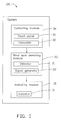
- FIG. 1 illustrates a block diagram of one embodiment of a blind spot detecting system 100 for a vehicle that includes an indicating module 10, a blind spot detecting module 20, and a controlling module 30.
- the indicating module 10 includes at least one indicator 11 that is electronically coupled to the blind spot detecting module 20.
- the blind spot detecting module 20 is configured to detect a presence or impending presence of object in a side lane next to the vehicle, and generate a detecting signal in response to detecting the presence or impending presence of the object.
- the controlling module 30 electronically coupled to the blind spot detecting module 20, and is configured to control the blind spot detecting module 20 to output the detecting signal to activate the at least one indicator 11.
- the blind spot detecting module 20 includes a detector 21 and a signal generator 22.
- the detector 21 is configured to detect the presence or impending presence of the object in a side lane next to the vehicle.
- the signal generator 22 is configured to generate the detecting signal in response to detecting the presence or impending presence of the object.
- the detector 21 detects the presence of an object (such as another vehicle) in the lane next to the host vehicle, where it may be difficult for the driver of the host vehicle to determine whether or not there is another vehicle adjacent to the host vehicle.
- the detector 21 can detect the presence or impending presence of the object outside the field of view of a side view mirror of the vehicle.
- the detector 21 is one of an imaging sensor, a radar sensor, an ultrasonic sensor and a sonar sensor.
- FIG. 2 illustrates a diagrammatic view of a vehicle 200 employing the blind spot detecting system 100 as shown in FIG. 1 .
- the vehicle 200 includes a lever switch 201, a driver's seat 202, and a side view mirror 203.
- the controlling module 30 includes a touch panel 31 mounted onto a surface of the lever switch 201 and a controller 32 (see FIG 1 ) electronically coupled to the touch panel 31.
- the controller 32 When an user, such as the driver of the vehicle 200, touches the touch panel 31, the controller 32 generates and outputs a controlling signal in response to a touch action detected by the touch panel 31.
- the control signal controls the signal generator 22 to output the detecting signal to activate the at least one indicator 11 (see FIG 1 ).
- the lever switch 201 can be a wiper lever switch or a turn signal lamp lever switch.
- one of the at least one detector 11 is a motor that is mounted into the lever switch 201. In another embodiment, one of the at least one detector 11 is a motor mounted into the driver's seat 202.
- the indicating module 20 includes two motors, one of the two motors is mounted into the lever switch 201, and the other of the two motors is mounted into the driver's seat 202.
- the side view mirror 203 includes a mirror casing 2031 and a reflecting element 2032.
- the detector 21 is mounted on the mirror casing 2031.
- the driver can touch the touch panel 31 mounted on the lever switch 201, if another vehicle is in the lane adjacent to the vehicle 200 is detected by the blind spot detecting module 20, the controller 32 then controls the signal generator 22 to output the detecting signal to activate the motor 11 mounted on the lever switch 201, such that, the driver can determine whether a collision risk exists.
Landscapes
- Engineering & Computer Science (AREA)
- Physics & Mathematics (AREA)
- General Physics & Mathematics (AREA)
- Computer Networks & Wireless Communication (AREA)
- Radar, Positioning & Navigation (AREA)
- Remote Sensing (AREA)
- Human Computer Interaction (AREA)
- Mechanical Engineering (AREA)
- Traffic Control Systems (AREA)
- Geophysics And Detection Of Objects (AREA)
- Steering Controls (AREA)
Applications Claiming Priority (1)
| Application Number | Priority Date | Filing Date | Title |
|---|---|---|---|
| TW102143873A TW201520107A (zh) | 2013-11-29 | 2013-11-29 | 轉向警示裝置及轉向警示方法 |
Publications (2)
| Publication Number | Publication Date |
|---|---|
| EP2887091A2 true EP2887091A2 (fr) | 2015-06-24 |
| EP2887091A3 EP2887091A3 (fr) | 2015-10-21 |
Family
ID=52006844
Family Applications (1)
| Application Number | Title | Priority Date | Filing Date |
|---|---|---|---|
| EP14194695.4A Withdrawn EP2887091A3 (fr) | 2013-11-29 | 2014-11-25 | Système de détection de l'angle mort d'un véhicule |
Country Status (4)
| Country | Link |
|---|---|
| US (1) | US20150154869A1 (fr) |
| EP (1) | EP2887091A3 (fr) |
| JP (1) | JP2015106415A (fr) |
| TW (1) | TW201520107A (fr) |
Families Citing this family (3)
| Publication number | Priority date | Publication date | Assignee | Title |
|---|---|---|---|---|
| EP3153366B1 (fr) * | 2015-10-07 | 2020-12-09 | Volvo Car Corporation | Système d'amélioration de la capacité d'observation de véhicule, véhicule comportant un tel système et procédé permettant d'augmenter la capacité d'observation de véhicule |
| DE102017002221A1 (de) * | 2017-03-08 | 2018-09-13 | Man Truck & Bus Ag | Technik zur Überwachung eines Totwinkelbereichs |
| CN110525343A (zh) * | 2019-09-18 | 2019-12-03 | 奇瑞汽车股份有限公司 | 汽车的变道控制方法、装置及存储介质 |
Family Cites Families (6)
| Publication number | Priority date | Publication date | Assignee | Title |
|---|---|---|---|---|
| US6812833B2 (en) * | 2002-04-12 | 2004-11-02 | Lear Corporation | Turn signal assembly with tactile feedback |
| JP2004086523A (ja) * | 2002-08-27 | 2004-03-18 | Suzuki Motor Corp | 車両用警戒情報提供装置 |
| US7859432B2 (en) * | 2007-05-23 | 2010-12-28 | Che Il Electric Wireing Devices Co., Ltd. | Collision avoidance system based on detection of obstacles in blind spots of vehicle |
| JP2010073134A (ja) * | 2008-09-22 | 2010-04-02 | Aisin Seiki Co Ltd | 車両周辺認知支援システム |
| US9493116B2 (en) * | 2012-06-22 | 2016-11-15 | GM Global Technology Operations LLC | Alert systems and methods for a vehicle |
| US8989916B2 (en) * | 2013-03-12 | 2015-03-24 | Volkswagen Ag | Vehicle signal lever proximity sensing for lane change intention detection with following recommendation to driver |
-
2013
- 2013-11-29 TW TW102143873A patent/TW201520107A/zh unknown
-
2014
- 2014-11-17 US US14/543,098 patent/US20150154869A1/en not_active Abandoned
- 2014-11-25 EP EP14194695.4A patent/EP2887091A3/fr not_active Withdrawn
- 2014-11-27 JP JP2014239771A patent/JP2015106415A/ja active Pending
Non-Patent Citations (1)
| Title |
|---|
| None |
Also Published As
| Publication number | Publication date |
|---|---|
| JP2015106415A (ja) | 2015-06-08 |
| US20150154869A1 (en) | 2015-06-04 |
| TW201520107A (zh) | 2015-06-01 |
| EP2887091A3 (fr) | 2015-10-21 |
Similar Documents
| Publication | Publication Date | Title |
|---|---|---|
| CN107031397B (zh) | 驾驶员疲劳状态警报系统及其方法 | |
| JP2019137392A (ja) | 単車用アダプティブクルーズコントロール標的追跡 | |
| CN105722716B (zh) | 内部显示系统和方法 | |
| US20100201508A1 (en) | Cross traffic alert system for a vehicle, and related alert display method | |
| US20180334089A1 (en) | Driving intention indicating device and method | |
| CN102470876B (zh) | 汽车的碰撞监控 | |
| US20210316660A1 (en) | Device and method for warning a driver of a vehicle | |
| EP1956574A3 (fr) | Système évitement de collision | |
| CN109664879B (zh) | 车辆用显示装置 | |
| JP2017091176A (ja) | 車両の運転支援装置 | |
| US20140142816A1 (en) | Method for operating a vehicle and vehicle | |
| US10919542B2 (en) | Apparatus and method for providing a kinesthetic cue in a driving automation equipped vehicle | |
| JP6676789B2 (ja) | 車両におけるアダプティブクルーズコントロールのための追い越し加速支援 | |
| JP2005165752A5 (fr) | ||
| JP6611083B2 (ja) | 車両制御装置 | |
| US20170080857A1 (en) | Tactical Threat Assessor for a Vehicle | |
| US20150154869A1 (en) | Vehicle blind spot detecting system | |
| US10055993B2 (en) | Systems and methods for control of mobile platform safety systems | |
| CN110114809B (zh) | 用于在具有变化的输出功能的光信号设备处提醒驾驶员起动的方法和装置 | |
| US12145443B2 (en) | Apparatus for recognizing a user position using at least one sensor and method thereof | |
| US7119666B2 (en) | Method for controlling and evaluating a sensor device shared by a plurality of applications | |
| JP2016153264A (ja) | 障害物検出装置 | |
| CN111095266A (zh) | 用于将信息从第一交通参与者发送至第二交通参与者以及用于接收从第一交通参与者发送至第二交通参与者的信息的方法和装置 | |
| CN207602038U (zh) | 交通号志灯号转换提醒系统 | |
| JP2018136713A (ja) | ドライバの視界推定装置及び車両用制御装置 |
Legal Events
| Date | Code | Title | Description |
|---|---|---|---|
| PUAI | Public reference made under article 153(3) epc to a published international application that has entered the european phase |
Free format text: ORIGINAL CODE: 0009012 |
|
| 17P | Request for examination filed |
Effective date: 20141125 |
|
| AK | Designated contracting states |
Kind code of ref document: A2 Designated state(s): AL AT BE BG CH CY CZ DE DK EE ES FI FR GB GR HR HU IE IS IT LI LT LU LV MC MK MT NL NO PL PT RO RS SE SI SK SM TR |
|
| AX | Request for extension of the european patent |
Extension state: BA ME |
|
| PUAL | Search report despatched |
Free format text: ORIGINAL CODE: 0009013 |
|
| AK | Designated contracting states |
Kind code of ref document: A3 Designated state(s): AL AT BE BG CH CY CZ DE DK EE ES FI FR GB GR HR HU IE IS IT LI LT LU LV MC MK MT NL NO PL PT RO RS SE SI SK SM TR |
|
| AX | Request for extension of the european patent |
Extension state: BA ME |
|
| RIC1 | Information provided on ipc code assigned before grant |
Ipc: B60Q 9/00 20060101ALI20150914BHEP Ipc: G08G 1/16 20060101ALI20150914BHEP Ipc: G01S 7/04 20060101AFI20150914BHEP Ipc: G01S 13/93 20060101ALI20150914BHEP |
|
| STAA | Information on the status of an ep patent application or granted ep patent |
Free format text: STATUS: THE APPLICATION IS DEEMED TO BE WITHDRAWN |
|
| 18D | Application deemed to be withdrawn |
Effective date: 20160422 |