EP2887100B1 - Procédé de téléchargement de données vers une unité centrale dans un système d'acquisition de données sismiques - Google Patents
Procédé de téléchargement de données vers une unité centrale dans un système d'acquisition de données sismiques Download PDFInfo
- Publication number
- EP2887100B1 EP2887100B1 EP13306800.7A EP13306800A EP2887100B1 EP 2887100 B1 EP2887100 B1 EP 2887100B1 EP 13306800 A EP13306800 A EP 13306800A EP 2887100 B1 EP2887100 B1 EP 2887100B1
- Authority
- EP
- European Patent Office
- Prior art keywords
- data
- concentrator
- central unit
- historic
- given
- Prior art date
- Legal status (The legal status is an assumption and is not a legal conclusion. Google has not performed a legal analysis and makes no representation as to the accuracy of the status listed.)
- Active
Links
Images





Classifications
-
- G—PHYSICS
- G06—COMPUTING OR CALCULATING; COUNTING
- G06F—ELECTRIC DIGITAL DATA PROCESSING
- G06F17/00—Digital computing or data processing equipment or methods, specially adapted for specific functions
- G06F17/40—Data acquisition and logging
-
- G—PHYSICS
- G01—MEASURING; TESTING
- G01V—GEOPHYSICS; GRAVITATIONAL MEASUREMENTS; DETECTING MASSES OR OBJECTS; TAGS
- G01V1/00—Seismology; Seismic or acoustic prospecting or detecting
- G01V1/22—Transmitting seismic signals to recording or processing apparatus
-
- G—PHYSICS
- G01—MEASURING; TESTING
- G01V—GEOPHYSICS; GRAVITATIONAL MEASUREMENTS; DETECTING MASSES OR OBJECTS; TAGS
- G01V1/00—Seismology; Seismic or acoustic prospecting or detecting
- G01V1/003—Seismic data acquisition in general, e.g. survey design
-
- G—PHYSICS
- G01—MEASURING; TESTING
- G01V—GEOPHYSICS; GRAVITATIONAL MEASUREMENTS; DETECTING MASSES OR OBJECTS; TAGS
- G01V1/00—Seismology; Seismic or acoustic prospecting or detecting
- G01V1/24—Recording seismic data
-
- H—ELECTRICITY
- H04—ELECTRIC COMMUNICATION TECHNIQUE
- H04L—TRANSMISSION OF DIGITAL INFORMATION, e.g. TELEGRAPHIC COMMUNICATION
- H04L67/00—Network arrangements or protocols for supporting network services or applications
- H04L67/01—Protocols
- H04L67/02—Protocols based on web technology, e.g. hypertext transfer protocol [HTTP]
Definitions
- the field of the invention is that of seismic data acquisition systems.
- the principle of operation of these systems is as follows: for a given experience, one or several seismic sources (explosives, falling weights, vibrators, air guns, etc.) are activated to propagate omnidirectional seismic wave trains; the wave trains reflected by the layers of the subsurface are detected by seismic sensors, which generate a signal characterizing the reflection of the waves on the geological interfaces of the subsurface.
- seismic sources explosive, falling weights, vibrators, air guns, etc.
- Experience refers to a seismic data acquisition operation. It begins with a seismic excitation with at least one source. It ends when all samples from all traces are recovered (retrieved), processed and released (typically under SEGD format).
- pending experience refers to a seismic data acquisition operation which is not yet ended, e.g. because there are data not yet recovered (referred to as “missing data”).
- the invention relates to a method for downloading data to a central unit (for example on-board a vehicle) in a seismic data acquisition system.
- the data can be seismic data (i.e. data obtained from the analog or digital seismic sensors) and/or information data (e.g. quality control (QC) data, state-of-health (SOH) data), etc).
- QC quality control
- SOH state-of-health
- the invention can be applied notably to the oil prospecting industry using seismic method, but can be of interest for any other field implementing a seismic data acquisition network.
- One particular application of the invention relates to land seismic data acquisition systems.
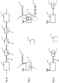
- FIG. 1a shows an example of seismic data acquisition system comprising a wired network, connected to a central unit 1 and comprising a plurality of acquisition lines 10.
- Each acquisition line 10 comprises:
- the data generated by the electronic unit(s) 2 comprise seismic data and/or information data (e.g. QC data, SOH data), etc).
- each acquisition line 10 is connected to the central unit 1 through one or several main wired links 7 (interconnected by intermediate modules 4), forming a main transverse line 7.
- each acquisition line 10 is connected to the central unit 1 through a wireless link (e.g. one of the intermediate module 4 has the ability to communicate wirelessly with the central unit, directly or through one or several other wireless modules and/or through one or several intermediate network devices).
- a cable cut causes a loss of connection with the electronic units 2 and the intermediate modules 4 situated after the cut and therefore the loss of all the seismic data corresponding to these electronic units 2.
- the electronic units 2 and the intermediate modules 4 are devised to only perform signal processing functions. In other words, they progressively return the seismic data (without storing them) to the central processing unit.
- a cable cut results in the irremediable loss of the seismic data corresponding to the sensors of the network section isolated by the cut.
- Each intermediate modules 4 comprises for example:
- the electronic units 2 are associated, by default, along the telemetry cable, with a predefined intermediate module 4, adjacent to the electronic unit (particularly with respect to data storage and synchronisation): the intermediate module (n - 1) is associated with the electronic unit(s) (n - 1), the intermediate module (n) is associated with the electronic unit(s) (n), the intermediate module (n + 1) is associated with the electronic unit(s) (n + 1), etc.
- an electronic unit n may be isolated from the associated module n.
- the alternative known solution of EP2189817 also makes it possible to remedy this situation: the bidirectional power supply means and the bidirectional storage means of each of the intermediate modules 4 make it possible to connect the electronic unit(s) (n) (isolated from the intermediate module (n) thereof) to the intermediate module (n + 1), or the intermediate module (n - 1) according to the position of the cut.
- the intermediate modules 4 also perform signal processing and interfacing functions, not shown in figure 1a , with the network (data transfer to the central unit 1, sending of commands received from the central unit 1 to the electronic units 2).
- the sensors are analog sensors 5, referred to as “geophones”, generally interconnected in groups of sensors by cables to form clusters referred to as “strings of geophones” 3.
- One or several of these strings are connected to each electronic unit 2 (also referred to as “Field Digitizing Unit") and this latter performs an analog to digital conversion of the signal from the groups of geophones and send these data to the central unit.
- the sensors are digital sensors 5' (e.g. micro-machined accelerometers, also referred to as "MEMS-based digital accelerometer”) integrated in the electronic units 2' (also referred to as “Digital Sensor Unit”), which eliminates the geophone strings.
- MEMS-based digital accelerometer e.g. micro-machined accelerometers, also referred to as "MEMS-based digital accelerometer”
- Each electronic unit 2' integrates one or several digital sensors 5'.
- the system comprises wireless modules (also referred to as "Remote Acquisition Units").
- Each wireless module is independent, associated with (i.e. is connected to or integrates one or several functions of) one or several electronic units (nodes) and communicates wirelessly (directly or through one or several other wireless modules and/or through one or several intermediate network devices) with the central unit and/or with a harvesting device (carried by an operator also referred to as “harvester") if a data harvesting strategy is implemented.
- the set of wireless modules could constitute a multi-hop wireless mesh network, allowing the wireless modules to exchange data, between them and with the central unit.
- each wireless module stores its own data (i.e. data obtained from the electronic unit(s) with which it is associated) and, eventually, also stores data received from one or several other wireless modules (i.e. data obtained from the electronic unit(s) associated with this or these other wireless modules).
- the sensors are analog sensors 5 and each wireless module 4' integrates one or a plurality of electronic unit(s) 2 identical to that of figure 1a (or integrates at least one of its functions, notably the digitizing function).
- the harvesting device is referenced 6.
- the sensors are digital sensors 5' and each wireless module 4" is connected, through a wired link 20' to an electronic unit 2' identical to that of figure 1b (i.e. which integrates one or several digital sensors 5').
- the harvesting device is referenced 6.
- WO 03/023448A2 describes a seismic data acquisition system comprising (see figure 1 ) a central recording system (CRS) 102, cross-line units (XLUs) 104 and data acquisition units (DAUs) 106, to which are coupled sensors 108.
- the DAUs 106 transmit data packets to the CRS 102.
- Each data packet includes one or more bits representing the sensed seismic signal and one or more bits for identifying the transmitted signal.
- a Field Equipment Interface (FEI) disposed in the CRS establishes a table in the CRS. This table contains a matrix of all the packets that are expected for an acquisition. As the FEI checks off the arrival of data packets, the matrix is examined for missing packets.
- FEI Field Equipment Interface
- the FEI sends a command for a specific remote unit to retransmit a specified packet based on its time sequence if a missing packet is detected. In other words, the table of received packets is examined for missing packets. If the table shows one or more missing packets, then commands are sent to DAUs to recover missing data from the DAU memory and retransmit the data package.
- a standard seismic data acquisition system comprises nodes (electronic units) and concentrators (intermediate modules or wireless modules).
- nodes electronic units
- concentrators intermediate modules or wireless modules.
- each node sends its data to a concentrator and this one keeps it in its memory.
- the central unit can retrieve the data related to this node by asking the concentrator.
- the problem is that, in some cases, the central unit is not aware of the location of all data and doesn't know which concentrator to ask for some of these data.
- the aforesaid problem starts when a node is located between two concentrators. Which concentrator is used to collect the data of this node? The left one or the right one? And what happens when a cut happens in the line during production?
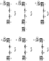
- FIGs 2a to 2h illustrate a series of examples explaining how it may be difficult sometimes to know exactly where, i.e. in which concentrator(s), the data of a node is located.
- the central unit CU is in the recorder and we want to determine where are stored the node N1 data (also referred to as "N1 data").
- the problem (lack of knowledge of some data location) exists when an acquisition line is autonomous and connected to the central unit through a wireless link.
- a first solution to the aforesaid problem would consist in building in the central unit an a-priori centralized database, describing the topology of the whole system (with all nodes and all concentrators), and providing for each node an exhausted list of the concentrators to ask to find the data, by making assumptions on cuts or disconnections in the system (which produce changes of the topology). For example, if the topology indicates that node N1 is located between concentrators C1 and C2, the central unit knows (from the a-priori centralized database) that the data of node N1 is handled either by concentrator C1 or concentrator C2 (there is no other possibility). Hence the central unit may first ask concentrator C1 for the N1 data and then concentrator C2 if it was not previously found.
- a main drawback of this first solution is the need for the central unit to build a complex a-priori centralized database, trying to determine in each case where the data is located (i.e. trying to have an exhaustive view of the location of all the data among the concentrators). As discussed above, in some cases the central unit may not be aware of the location of the data and won't know which concentrator ask for it.
- Another drawback of this first solution is that if some data are forgotten in a concentrator, it is difficult for the central unit to retrieve them (e.g. several days later), especially if the central unit has been stop or rebooted in the meantime or if the concentrator has been laid out away and connected to other nodes.
- a second solution would be to ask all concentrators for a specific data.
- the data flow it would generate would be important and occupy a large bandwidth in the different transmission lines.
- a third solution would be to broadcast a data query on the whole system. It would appear ineffective timewise as well as the concentrator might deal with multiple queries implying processing and consuming CPU time. Also, broadcasting a query occupies a great bandwidth as the message is propagated to the whole system.
- the invention in at least one embodiment, is aimed especially at overcoming these different drawbacks of the prior art.
- a particular embodiment of the invention proposes a method for downloading data to a central unit according to Claim 1.
- each module concentrateator
- the central unit does not need a complex a-priori centralized database to locate the missing data.
- the proposed solution is based on the use of a mechanism comprising the sending of historics of data by the modules (when they are connected to the central unit) and the cross-check of these historics with the missing data, in order to enable the central unit to know where (i.e. in which modules) are stored the missing data and obtain them from the modules in question.
- the proposed solution allows to retrieve missing data forgotten in a module (even if it is several days later, and even if the central unit has been stop or rebooted, or if the module has been laid out away and connected to other electronic units), as soon as this module is connected to the central unit.
- said data stored in said given module belong to the group comprising seismic data and information data.
- the data can be seismic data (i.e. data obtained from the analog or digital seismic sensors), and/or information data (e.g. QC data, SOH data, etc.).
- seismic data i.e. data obtained from the analog or digital seismic sensors
- information data e.g. QC data, SOH data, etc.
- said data stored in said given module belong to the group comprising:
- said network comprises at least one acquisition line comprising a telemetry cable along which are assembled at least two modules and at least two electronic units in series, each of said at least two electronic units being connected to at least one analog seismic sensor or integrating at least one digital seismic sensor.
- the proposed solution can be implemented in the context of figures 1a and 1b , i.e. with modules (concentrators) which are "intermediate modules" as defined above.
- said network comprises at least two modules, each acting as a wireless remote acquisition device and each:
- the historic sent by said given module to the central unit is a complete historic comprising at least one normal set of information comprising at least: a time interval, and a list of electronic unit(s) whose data for said time interval are stored by said given module.
- the historic for a given module is a temporal description, comprising one or several sets of information, each set of information being representative of data stored in said given module during a given time interval.
- the historic can be chronological (in this case the time intervals are successive) but it can also be non-chronological (in this case the time intervals are for example provided in a random order).
- the central unit sends a time limit to said given module
- the historic sent by said given module to the central unit is a partial historic, compared with a complete historic comprising at least one normal set of information comprising at least: a time interval, and a list of electronic unit(s) whose data for said time interval are stored by said given module.
- Said partial historic is limited to the time between said time limit and a current time.
- the complete historic may need a great amount of data to be transmitted.
- the second implementation allows to reduce this great amount of data, by sending only a partial historic, which can be seen as the result of a temporal filtering of the complete historic.
- said time limit belongs to the group comprising: the date of an oldest sample missing to the central unit; and the date of reception by the central unit of the previous historic sent by said given module.
- the historic sent by said given module to the central unit is an augmented historic, compared with a complete historic comprising at least one normal set of information comprising at least: a time interval, and a list of electronic unit(s) whose data for said time interval are stored by said given module.
- Said augmented historic comprises at least one augmented set of information having an augmented time interval and/or an augmented list of electronic unit(s), said at least one augmented set of information replacing at least two normal sets of information.
- the third implementation also allows to reduce the aforesaid great amount of data, by sending an augmented historic which is simpler than the complete historic and therefore comprises less data to be transmitted.
- said at least two normal sets of information, replaced by said at least one augmented set of information relate to at least two adjacent time intervals belonging to a group comprising:
- the central unit does not need a complex a-priori centralized database, describing the topology of the whole system and providing for each electronic unit (node) an exhausted list of the modules (concentrators) to ask to find the data, by making assumptions on cuts or disconnections in the system (which produce changes of the topology). Instead, for the pending experience, the central unit:
- the central unit in the step of obtaining at least some of the missing data from the given module, carries out a step belonging to the group comprising:
- the fact to know where the missing data are stored is optimal: in the first case, it allows the central unit to send a minimum number of queries (missing data requests), and in the second case it allows to optimize the harvester journey on the field (allowing him to focus on modules having the requested missing data).
- the method comprises the following step: said given module sends to the central unit a description indicating the electronic unit(s) of which it stores data at a current connection time, allowing the central unit to know if said given module should be queried for at least one future experience.
- the module sends to the central unit a description which will be used during the first phase of at least one future experience.
- the invention pertains to a computer program product comprising program code instructions according to Claim 13.
- the invention pertains to a non-transitory computer-readable carrier medium, storing a program according to Claim 14.
- the invention pertains to a seismic data acquisition system according to Claim 15.
- the system comprises means for implementing the steps of the process as described above, in any of its various embodiments.
- the proposed solution applies with any seismic data acquisition system comprising a central unit, concentrators (modules) and nodes (electronic units).
- the proposed solution can also be applied, notably but not exclusively, with the implementations of figures 1b, 1c and Id.
- seismic data i.e. data obtained from the seismic sensors.
- information data e.g. QC data, SOH data, etc.
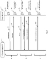
- FIG 3 is a sequence diagram illustrating a method for downloading data to the central unit 1, according to a particular embodiment of the invention.
- This sequence diagram implies the central unit 1 and a concentrator 4 (noted Ci to show it is a generic explanation, which applies to all concentrators).
- phase b follows phase a.
- phase c is executed after phase a, but the reverse is also possible. Phases a and c can even be executed simultaneously.
- the central unit tries to know in which concentrators (called hereafter “selected concentrators”) are stored the data of the nodes involved in a pending experience. For this purpose, it queries a connection database (or any other appropriate storing means) which stores descriptions previously sent to the central unit by all the concentrators (or certain of them) during previous experience(s). Each stored description indicates the nodes managed by the concentrator which has sent this description, at a previous connection time. At the current time, it is possible that this concentrator doesn't manage any more the same nodes, but the central unit doesn't know it. As a function of the content of the connection database, the central unit obtains a list of selected concentrators, and a list of managed nodes for each selected concentrator.
- concentrator Ci is a selected concentrator.
- step 32 the central unit sends a query (data request) for data to the concentrator Ci, specifying the nodes for which data are expected.
- the central unit receives a response from the concentrator Ci, comprising only some of the requested data if the concentrator Ci doesn't manage any more the same nodes. According to an example that is not claimed, the central unit receives a response from the concentrator Ci comprising the requested data.
- step 34 the central unit determines the missing data, i.e. the data requested to all the selected concentrators, but not received from them.
- the concentrator Ci sends to it a historic of the data stored in the concentrator Ci.
- the historic sent by the concentrator Ci is a complete historic comprising one or several sets of information each comprising at least a time interval and a list of node(s) associated with the concentrator Ci during said time interval, and whose data for said time interval are stored by the concentrator Ci.
- Each set of information can also comprise supplemental data (e.g. the GPS position of the nodes).
- the historic is for example chronological (i.e. the time intervals are successive) but it can also be non-chronological (the time intervals are for example provided in a random order).
- step 36 the central unit cross-checks the historic (received in step 35) with missing data (determined in step 34).
- step 37 the central unit sends a query (missing data request) for missing data to the concentrator Ci.
- step 38 the central unit receives a response from the concentrator Ci, comprising the requested missing data (i.e. the part of the missing data stored by the concentrator Ci).
- the central unit obtains missing data from the concentrator Ci via a portable unit (also referred to as “harvesting device") carried by an operator (also referred to as “harvester”) and linked (the link may be of any type, wired or wireless, known to those skilled in the art) with the concentrator Ci.
- the central unit generates a list of nodes and timestamps to collect and transfers it to the harvesting device. This list will be submitted by the harvesting device to the concentrator.
- step 39 the central unit updates, with the data obtained from the concentrator Ci, a pending experience database (or any other appropriate storing means) which stores the data received from all the concentrators for the pending experience.
- step 310 when it is connected (via a wired or wireless link) to the central unit, the concentrator Ci sends to the central unit a description of the node(s) it manages at the current connection time.
- step 311 the central unit updates, with the description received in step 310, the connection database. This allows the central unit to know if the concentrator Ci should be queried for at least one future experience.
- Figure 4 illustrates the step 310 (sending of a description) of the method of figure 3 .
- the concentrator C1 manages the nodes N1 and N2 and the concentrator C2 manages the nodes N3 and N4.
- the concentrator Ci is C2.
- the description sent by the concentrator C2 indicates this ("I am C2") and the fact that C2 manages (i.e. controls) the nodes N3 and N4 at the current connection time.
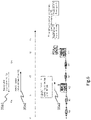
- Figure 5 illustrates the step 35 (sending of a historic) of the method of figure 3 .
- the concentrator C1 manages the nodes N1 and N2 and the concentrator C2 manages the nodes N3 and N4.
- the concentrator Ci is C2.
- the nodes N1 and N2 are managed by the concentrator C2.
- the historic sent by the concentrator C2, determined at a current time t4, comprises the following sets of information (each comprising at least a time interval and a list of node(s)):
- FIG 6 illustrates a first variant of the step 35 (sending of a historic) of the method of figure 3 .
- the concentrator Ci may have in memory data acquired few days before. It's useless to send the historic of these data if the central unit doesn't need it. For this reason the historic is not automatically send by the concentrator, but only on request (step 35a1) of the central unit which provides the concentrator with a time limit which is the GPS date of its oldest missing sample. Then the concentrator can provide (step 35a2) a historic limited to the time between this time limit and the current time.
- the historic, determined at a current time t4, comprises the following sets of information:
- Figure 7 illustrates a second variant of the step 35 (sending of a historic) of the method of figure 3 . If there are several cuts/repairs of the line, each time it comes back, the concentrator Ci will send back its historic to the central unit. It is useless, expensive in bandwidth and the central unit has to manage again the part of historic already received.
- the proposed solution is for the central unit to note the date of reception of the previous historic sent by the concentrator Ci (if it was managed without any error). Next time the concentrator Ci comes back, it is requested by the central unit to limit the historic to the end of its previous historic.
- the historic is not automatically sent by the concentrator, but only on request (step 35b1) of the central unit which provides the concentrator with a time limit which is the date of reception of the previous historic sent by the concentrator Ci. Then the concentrator can provide (step 35b2) a historic limited to the time between this time limit and the current time.
- Figure 8 illustrates a third variant of the step 35 (sending of a historic) of the method of figure 3 .
- the idea is that the historic sent by the concentrator Ci to the central unit is an augmented historic, compared with a complete historic (see figure 5 ) comprising at least one normal pair set of information comprising at least:
- the augmented historic comprises one or several augmented sets of information having an augmented time interval and/or an augmented list of node(s). Each augmented set of information replaces at least two normal sets of information.
- the concentrator sends an augmented historic complying with the following rules:
- This tolerance provides a great simplification of the historic.
- the at least two normal sets of information, replaced by a given augmented set of information relate to at least two adjacent time intervals with different lists of node(s), these different lists of node(s) resulting from a change in topology of the network (e.g. a line cut).
- FIG 8 illustrates that after a line cut, we don't need to know the exact GPS date (precise at the sample rate) of the cut.
- the concentrator C1 and C2 we assume that a line cut, between N1 and C1, occurred (let say at t2), but in fact the cut doesn't occur at the same time for each node (let say t2- ⁇ 1 for N2 an t2+ ⁇ 2 for N1).
- the consequence leads to very long historics when you have a great number of nodes (i.e. more than only N1 and N2 in the simplified above example).
- the proposed solution simplifies the historic, by generating an augmented historic.
- C1 is allowed to declare data for N1 and N2 after t2.
- C2 is allowed to declare data for N1 and N2 before t2. There is an overlap.
- the augmented historic of C1 comprises the following set of information:
- the augmented historic of C2 (sent at step 35c) comprises the following set of information:
- t3 is not the time at which the line was repaired.
- Figure 9 illustrates a fourth variant of the step 35 (sending of a historic) of the method of figure 3 .
- the idea is that the historic sent by the concentrator Ci to the central unit is an augmented historic, with a tolerance providing a great simplification compared with the complete (theoretical) historic.
- the at least two normal sets of information, replaced by a given augmented set of information relate to at least two non-adjacent time intervals with a same list of electronic unit(s), said at least two non-adjacent time intervals corresponding to different acquisition periods, without change in topology of the network and separated by at least one non-acquisition period.
- only a change in the topology leads to a change in the augmented historic.
- the augmented historic of C2 (sent at step 35d) comprises the following sets of information:
- Figure 10 presents the simplified structure of an intermediate module (concentrator) 4 according to a particular embodiment of the invention. It comprises a non-volatile memory 403 (e.g. a read-only memory (ROM)), a volatile memory 401 (e.g. a random access memory (RAM)) and a processor 402.
- the non-volatile memory 403 (non-transitory computer-readable carrier medium) stores executable program code instructions, which are executed by the processor 402 in order to enable implementation, by the concentrator 4, of the method described above (see figures 3-9 ).
- the aforementioned program code instructions are transferred from the non-volatile memory 403 to the volatile memory 401 so as to be executed by the processor 402.
- the volatile memory 401 likewise includes registers for storing the variables and parameters required for this execution.
- Figure 11 presents the simplified structure of the central unit 1 according to a particular embodiment of the invention. It comprises a non-volatile memory 103 (e.g. a hard disk), a volatile memory 401 (e.g. a random access memory (RAM)) and a processor 102.
- the non-volatile memory 103 (non-transitory computer-readable carrier medium) stores executable program code instructions, which are executed by the processor 102 in order to enable implementation, by the central unit 1, of the method described above (see figures 3-9 ).
- the aforementioned program code instructions are transferred from the non-volatile memory 103 to the volatile memory 101 so as to be executed by the processor 102.
- the volatile memory 101 likewise includes registers for storing the variables and parameters required for this execution.
Landscapes
- Engineering & Computer Science (AREA)
- Physics & Mathematics (AREA)
- Remote Sensing (AREA)
- Life Sciences & Earth Sciences (AREA)
- General Physics & Mathematics (AREA)
- Acoustics & Sound (AREA)
- Environmental & Geological Engineering (AREA)
- Geology (AREA)
- General Life Sciences & Earth Sciences (AREA)
- Geophysics (AREA)
- General Engineering & Computer Science (AREA)
- Theoretical Computer Science (AREA)
- Computer Networks & Wireless Communication (AREA)
- Signal Processing (AREA)
- Computer Hardware Design (AREA)
- Data Mining & Analysis (AREA)
- Databases & Information Systems (AREA)
- Mathematical Physics (AREA)
- Software Systems (AREA)
- Geophysics And Detection Of Objects (AREA)
- Arrangements For Transmission Of Measured Signals (AREA)
Claims (15)
- Procédé de téléchargement de données impliquées dans au moins une opération d'acquisition de données sismiques en attente, appelée « au moins une expérience en attente », vers une unité centrale (1) d'un système d'acquisition de données sismiques, ledit système d'acquisition de données sismiques comprenant en outre un réseau connecté à ladite unité centrale (1), ledit réseau incluant une pluralité de modules (4), appelés « concentrateurs », et une pluralité d'unités électroniques (2), également appelées « nœuds » ;chaque unité électronique (2) étant connectée à au moins un capteur sismique analogique (5) ou intégrant au moins un capteur sismique numérique (5'), et étant configurée de manière à traiter des signaux transmis par ledit au moins un capteur sismique (5, 5') en vue de générer des données correspondantes ;chaque concentrateur (4) étant apte à gérer au moins une unité électronique (2) en recevant et en stockant des données générées par ladite au moins une unité électronique (2) ; et l'unité centrale (1) étant configurée de manière à interroger une base de données de connexion qui stocke des descriptions indiquant les unités électroniques gérées par un concentrateur pendant une expérience précédente ;caractérisé en ce que le procédé comprend les étapes ci-dessous consistant à :- sur la base des descriptions stockées, obtenir (31), par le biais de l'unité centrale (1), une liste de concentrateurs sélectionnés (Ci), parmi ladite pluralité de concentrateurs (4), qui, au cours de l'expérience précédente, ont géré une ou des unités électroniques qui sont impliquées dans une expérience en attente, et une liste d'au moins une unité électronique gérée (2) pour chaque concentrateur sélectionné ;- envoyer (32), par le biais de l'unité centrale (1), une demande de données concernant des données de ladite au moins une expérience en attente, à chaque concentrateur sélectionné (Ci), en spécifiant les unités électroniques (2) pour lesquelles des données sont attendues ;- recevoir (33), par le biais de l'unité centrale (1), en provenance de chaque concentrateur sélectionné (Ci), une réponse comprenant uniquement certaines des données demandées lorsque le concentrateur sélectionné (Ci) ne gère plus les mêmes unités électroniques que lors de l'expérience précédente ;- déterminer (34), par le biais de l'unité centrale (1), un ensemble d'informations identifiant les données d'au moins une expérience en attente, appelées « données manquantes », qui ont été demandées aux concentrateurs sélectionnés, mais qui n'ont pas été reçues par l'unité centrale (1), en provenance des concentrateurs sélectionnés ; eten ce que le procédé comprend les étapes ci-dessous, pour chaque concentrateur donné (4), consistant à :- générer, par le biais dudit concentrateur donné (4), un historique des données de ladite au moins une expérience en attente qui sont stockées dans le concentrateur donné (4), ledit historique étant une description temporelle, chronologique ou non, comprenant un ou plusieurs ensembles d'informations, chaque ensemble d'informations étant représentatif de données générées par ladite au moins une unité électronique (2) qui sont stockées dans ledit concentrateur donné pendant un intervalle de temps donné de ladite au moins une expérience en attente ;- envoyer (35), par le biais dudit concentrateur donné (4), ledit historique, à l'unité centrale (1) ;- effectuer une vérification croisée (36), par le biais de l'unité centrale (1), dudit historique avec ledit ensemble d'informations identifiant les données manquantes ; et- en cas de correspondance dudit historique avec l'ensemble d'informations identifiant les données manquantes :- envoyer (37), par le biais de l'unité centrale (1), une requête pour lesdites données manquantes, au concentrateur donné (4) ; et- recevoir (38), par le biais de l'unité centrale (1), une réponse en provenance dudit concentrateur donné, comprenant les données manquantes demandées.
- Procédé selon la revendication 1, caractérisé en ce que lesdites données stockées dans ledit concentrateur donné (4) appartiennent au groupe comprenant des données sismiques et des données d'information.
- Procédé selon l'une quelconque des revendications 1 à 2, caractérisé en ce que, pour un intervalle de temps donné, lesdites données stockées dans ledit concentrateur donné (4) appartiennent au groupe comprenant :- des données obtenues à partir d'au moins une unité électronique (2) associée audit concentrateur donné (4) au cours dudit intervalle de temps ; et- des données obtenues à partir d'au moins une unité électronique (2) associée à un autre concentrateur, différent dudit concentrateur donné, au cours dudit intervalle de temps.
- Procédé selon l'une quelconque des revendications 1 à 3, caractérisé en ce que ledit réseau comprend au moins une ligne d'acquisition (10) comprenant un câble de télémétrie (20) le long duquel sont assemblés au moins deux concentrateurs (4) et au moins deux unités électroniques (2) en série, chacune desdites au moins deux unités électroniques étant connectée à au moins un capteur sismique analogique (5) ou intégrant au moins un capteur sismique numérique (5').
- Procédé selon l'une quelconque des revendications 1 à 3, caractérisé en ce que ledit réseau comprend au moins deux concentrateurs (4', 4"), chacun agissant en qualité de dispositif de téléacquisition sans fil et chacun :- intégrant au moins une fonction de numérisation d'une unité électronique (2) et étant connecté à au moins un capteur sismique analogique (5) ; ou- étant connecté à une unité électronique (2) intégrant au moins un capteur sismique numérique (5').
- Procédé selon l'une quelconque des revendications 1 à 5, caractérisé en ce que l'historique envoyé par ledit concentrateur donné (4) à l'unité centrale (1) est un historique complet comprenant au moins un ensemble normal d'informations comprenant au moins :- un intervalle de temps ; et- une liste d'une ou plusieurs unités électroniques (2) dont les données pour ledit intervalle de temps sont stockées par ledit concentrateur donné (4).
- Procédé selon l'une quelconque des revendications 1 à 5, caractérisé en ce que, l'unité centrale (1) envoie une limite de temps audit concentrateur donné (4), et en ce que l'historique envoyé par ledit concentrateur donné (4) à l'unité centrale (1) est un historique partiel, par rapport à un historique complet comprenant au moins un ensemble normal d'informations comprenant au moins :- un intervalle de temps ; et- une liste d'une ou plusieurs unités électroniques (2) dont les données pour ledit intervalle de temps sont stockées par ledit concentrateur donné (4) ;ledit historique partiel étant limité au temps compris entre ledit intervalle de temps et une heure en cours.
- Procédé selon la revendication 7, caractérisé en ce que ladite limite de temps appartient au groupe comprenant :- la date d'un échantillon le plus ancien manquant à l'unité centrale (1) ; et- la date de réception, par l'unité centrale (1), de l'historique précédent envoyé par ledit concentrateur donné.
- Procédé selon l'une quelconque des revendications 1 à 5, caractérisé en ce que l'historique envoyé par ledit concentrateur donné (4) à l'unité centrale (1) est un historique augmenté, par rapport à un historique complet comprenant au moins un ensemble normal d'informations comprenant au moins :- un intervalle de temps ; et- une liste d'une ou plusieurs unités électroniques (2) dont les données pour ledit intervalle de temps sont stockées par ledit concentrateur donné (4) ;ledit historique augmenté comprenant au moins un ensemble augmenté d'informations présentant un intervalle de temps augmenté et/ou une liste augmentée d'une ou plusieurs unités électroniques (2), ledit au moins un ensemble augmenté d'informations remplaçant au moins deux ensembles normaux d'informations.
- Procédé selon la revendication 9, caractérisé en ce que lesdits au moins deux ensembles normaux d'informations, remplacés par ledit au moins un ensemble augmenté d'informations, concernent au moins deux intervalles de temps adjacents appartenant à un groupe comprenant :- au moins deux intervalles de temps adjacents avec différentes listes d'une ou plusieurs unités électroniques (2), lesdites différentes listes d'une ou plusieurs unités électroniques (2) résultant d'un changement topologique dudit réseau ; et- au moins deux intervalles de temps non adjacents avec une même liste d'une ou plusieurs unités électroniques (2), lesdits au moins deux intervalles de temps non adjacents correspondant à différentes périodes d'acquisition, sans changement topologique dudit réseau et séparées par au moins une période de non-acquisition.
- Procédé selon l'une quelconque des revendications 1 à 10, caractérisé en ce que, à l'étape d'obtention d'au moins certaines des données manquantes à partir du concentrateur donné (4), l'unité centrale met en œuvre une étape appartenant au groupe comprenant les étapes ci-dessous dans lesquelles :- l'unité centrale (1) envoie (37) une demande de données manquantes audit concentrateur donné (4), et reçoit (38), en réponse, au moins certaines des données manquantes ;- l'unité centrale (1) transmet des informations à un dispositif de collecte qui, lorsqu'il est actionné par un opérateur de terrain, collecte au moins certaines des données manquantes à partir dudit concentrateur donné (4) et les fournit à l'unité centrale (1).
- Procédé selon l'une quelconque des revendications 1 à 11, caractérisé en ce qu'il comprend l'étape ci-dessous dans laquelle :- ledit module donné (4), envoie (310), à l'unité centrale (1), une description indiquant la ou les unités électroniques (2) dont il stocke les données à un instant de connexion en cours, permettant à l'unité centrale (1) de savoir si ledit concentrateur donné (4) doit être interrogé pour au moins une expérience future.
- Produit-programme informatique, caractérisé en ce qu'il comprend des instructions de code de programme pour mettre en œuvre le procédé selon l'une au moins des revendications 1 à 12, lorsque ledit produit-programme est exécuté sur un ordinateur ou un processeur (402) de chaque concentrateur (4), et sur un ordinateur ou un processeur (102) de l'unité centrale (1).
- Support porteur non transitoire lisible par ordinateur stockant un programme qui, lorsqu'il est exécuté par un ordinateur ou un processeur (402) de chaque concentrateur (4) et par un ordinateur ou un processeur (102) de l'unité centrale (1), amène l'ordinateur ou le processeur à mettre en œuvre le procédé selon au moins l'une des revendications 1 à 12.
- Système d'acquisition de données sismiques destiné à télécharger des données impliquées dans au moins une opération d'acquisition de données sismiques en attente, appelée « au moins une expérience en attente », vers une unité centrale (1),ledit système d'acquisition de données sismiques comprenant ladite unité centrale (1) et un réseau connecté à ladite unité centrale (1), ledit réseau incluant une pluralité de modules (4), appelés « concentrateurs », et une pluralité d'unités électroniques (2), également appelées « nœuds », chaque unité électronique (2) étant connectée à au moins un capteur sismique analogique (5) ou intégrant au moins un capteur sismique numérique (5'), et étant configurée de manière à traiter des signaux transmis par ledit au moins un capteur sismique (5, 5') en vue de générer des données correspondantes ;chaque concentrateur (4) étant apte à gérer au moins une unité électronique (2) en recevant et en stockant des données générées par ladite au moins une unité électronique (2) ; et l'unité centrale (1) étant configurée de manière à interroger une base de données de connexion qui stocke des descriptions indiquant les unités électroniques gérées par un concentrateur pendant une expérience précédente ;caractérisé en ce que le système d'acquisition de données sismiques (1) est configuré de manière à :- sur la base des descriptions stockées, obtenir (31), par le biais de l'unité centrale (1), une liste de concentrateurs sélectionnés (Ci), parmi ladite pluralité de concentrateurs (4), qui, au cours de l'expérience précédente, ont géré une ou des unités électroniques qui sont impliquées dans une expérience en attente, et une liste d'au moins une unité électronique gérée (2) pour chaque concentrateur sélectionné ;- envoyer (32), par le biais de l'unité centrale (1), une demande de données concernant des données de ladite au moins une expérience en attente, à chaque concentrateur sélectionné (Ci), en spécifiant les unités électroniques (2) pour lesquelles des données sont attendues ;- recevoir (33), par le biais de l'unité centrale (1), en provenance de chaque concentrateur sélectionné (Ci), une réponse comprenant uniquement certaines des données demandées lorsque le concentrateur sélectionné (Ci) ne gère plus les mêmes unités électroniques que lors de l'expérience précédente ;- déterminer (34), par le biais de l'unité centrale (1), un ensemble d'informations identifiant les données d'au moins une expérience en attente, appelées « données manquantes », qui ont été demandées aux concentrateurs sélectionnés, mais qui n'ont pas été reçues par l'unité centrale (1), en provenance des concentrateurs sélectionnés ;- pour chaque concentrateur donné (4), générer, par le biais dudit concentrateur donné (4), un historique des données de ladite au moins une expérience en attente qui sont stockées dans le concentrateur donné (4) ;ledit historique étant une description temporelle, chronologique ou non, comprenant un ou plusieurs ensembles d'informations, chaque ensemble d'informations étant représentatif de données générées par ladite au moins une unité électronique (2) qui sont stockées dans ledit concentrateur donné pendant un intervalle de temps donné de ladite au moins une expérience en attente ;- envoyer (35), par le biais dudit concentrateur donné (4), ledit historique, à l'unité centrale (1) ;- effectuer une vérification croisée (36), par le biais de l'unité centrale (1), dudit historique avec ledit ensemble d'informations identifiant les données manquantes ; et- en cas de correspondance dudit historique avec l'ensemble d'informations identifiant les données manquantes :- envoyer (37), par le biais de l'unité centrale (1), une requête pour lesdites données manquantes, au concentrateur donné (4) ; et- recevoir (38), par le biais de l'unité centrale (1), une réponse en provenance dudit concentrateur donné, comprenant les données manquantes demandées.
Priority Applications (5)
| Application Number | Priority Date | Filing Date | Title |
|---|---|---|---|
| EP13306800.7A EP2887100B1 (fr) | 2013-12-20 | 2013-12-20 | Procédé de téléchargement de données vers une unité centrale dans un système d'acquisition de données sismiques |
| CA2873429A CA2873429C (fr) | 2013-12-20 | 2014-12-03 | Procede pour telecharger des donnees vers une unite centrale dans un systeme d'acquisition de donnees sismiques |
| CN201410790208.8A CN104730570B (zh) | 2013-12-20 | 2014-12-17 | 用于将数据下载到地震数据采集系统中的中央单元的方法 |
| RU2014151707A RU2675899C2 (ru) | 2013-12-20 | 2014-12-19 | Способ загрузки данных в центральный модуль в системе получения сейсмических данных |
| US14/578,369 US10007014B2 (en) | 2013-12-20 | 2014-12-20 | Method for downloading data to a central unit in a seismic data acquisition system |
Applications Claiming Priority (1)
| Application Number | Priority Date | Filing Date | Title |
|---|---|---|---|
| EP13306800.7A EP2887100B1 (fr) | 2013-12-20 | 2013-12-20 | Procédé de téléchargement de données vers une unité centrale dans un système d'acquisition de données sismiques |
Publications (2)
| Publication Number | Publication Date |
|---|---|
| EP2887100A1 EP2887100A1 (fr) | 2015-06-24 |
| EP2887100B1 true EP2887100B1 (fr) | 2022-10-26 |
Family
ID=49955848
Family Applications (1)
| Application Number | Title | Priority Date | Filing Date |
|---|---|---|---|
| EP13306800.7A Active EP2887100B1 (fr) | 2013-12-20 | 2013-12-20 | Procédé de téléchargement de données vers une unité centrale dans un système d'acquisition de données sismiques |
Country Status (5)
| Country | Link |
|---|---|
| US (1) | US10007014B2 (fr) |
| EP (1) | EP2887100B1 (fr) |
| CN (1) | CN104730570B (fr) |
| CA (1) | CA2873429C (fr) |
| RU (1) | RU2675899C2 (fr) |
Families Citing this family (5)
| Publication number | Priority date | Publication date | Assignee | Title |
|---|---|---|---|---|
| JP6447723B2 (ja) * | 2015-06-05 | 2019-01-09 | 富士通株式会社 | 観測システムおよび観測方法 |
| DE102017201514B4 (de) * | 2017-01-31 | 2022-11-03 | Volkswagen Aktiengesellschaft | Verfahren für ein Fahrzeug einer Fahrzeugflotte zur Übertragung von Daten an eine Datenverarbeitungsanlage, Verfahren für eine Datenverarbeitungsanlage zum Übertragen von Daten einer Fahrzeugflotte an die Datenverarbeitungsanlage sowie Fahrzeug |
| CN112799152A (zh) * | 2019-11-13 | 2021-05-14 | 中国石油天然气集团有限公司 | 节点单元质控数据检测系统及方法 |
| CN111666261B (zh) * | 2020-05-11 | 2023-04-07 | 中国科学院地质与地球物理研究所 | 一种基于地震数据流的嵌入式文件网络服务器 |
| JP7260184B2 (ja) * | 2020-12-03 | 2023-04-18 | Necプラットフォームズ株式会社 | 災害検知システム、管理用端末装置及び災害検知方法及び災害検知プログラム |
Family Cites Families (16)
| Publication number | Priority date | Publication date | Assignee | Title |
|---|---|---|---|---|
| FR2720518B1 (fr) * | 1994-05-26 | 1996-07-12 | Inst Francais Du Petrole | Système d'acquisition et de transmission sismique avec décentralisation des fonctions. |
| US6735630B1 (en) * | 1999-10-06 | 2004-05-11 | Sensoria Corporation | Method for collecting data using compact internetworked wireless integrated network sensors (WINS) |
| US6977867B2 (en) * | 2001-06-05 | 2005-12-20 | Geo-X Systems, Ltd. | Seismic data acquisition system |
| US20030128627A1 (en) * | 2001-09-07 | 2003-07-10 | Input/Output, Inc. | Seismic data acquisition apparatus and method |
| US20050047275A1 (en) * | 2003-09-01 | 2005-03-03 | Geo-X Systems, Ltd. | Synchronization and positioning of seismic data acquisition systems |
| EP2024762A4 (fr) * | 2006-06-09 | 2012-11-07 | Inova Ltd | Acquisition de donnees sismiques |
| US7813222B2 (en) * | 2007-02-01 | 2010-10-12 | Ion Geophysical Corporation | Apparatus and method for compressing seismic data |
| US8358220B2 (en) * | 2007-03-27 | 2013-01-22 | Shell Oil Company | Wellbore communication, downhole module, and method for communicating |
| US7805248B2 (en) * | 2007-04-19 | 2010-09-28 | Baker Hughes Incorporated | System and method for water breakthrough detection and intervention in a production well |
| GB0725276D0 (en) * | 2007-12-28 | 2008-02-06 | Vibration Technology Ltd | Seismic data recording |
| RU78333U1 (ru) * | 2008-06-30 | 2008-11-20 | Тихоокеанский океанологичнский институт им. В.И. Ильичева Дальневосточного отделения Российской академии наук (ТОИ ДВО РАН) | Газогидроакустический комплекс для оценки сейсмотектонической активизации |
| US20120106296A1 (en) * | 2008-11-25 | 2012-05-03 | Sercel | Seismic data acquisition system comprising modules associated with units connected to sensors, the modules being autonomous with respect to power supply, synchronisation and storage |
| FR2938928B1 (fr) | 2008-11-25 | 2011-01-21 | Sercel Rech Const Elect | Systeme d'acquisition de donnees sismiques comprenant des modules associes a des boitiers relies a des capteurs, les modules etant autonomes en alimentation, synchronisation et memorisation. |
| US20100257004A1 (en) * | 2009-04-01 | 2010-10-07 | Chervon U.S.A. Inc. | Method and system for conducting geologic basin analysis |
| EP2657725B1 (fr) * | 2012-04-27 | 2015-01-14 | Sercel | Procédé et système de gestion d'un système de plusieurs navires |
| US9618640B2 (en) * | 2013-06-17 | 2017-04-11 | INOVA, Ltd. | Removing offset from seismic signals |
-
2013
- 2013-12-20 EP EP13306800.7A patent/EP2887100B1/fr active Active
-
2014
- 2014-12-03 CA CA2873429A patent/CA2873429C/fr active Active
- 2014-12-17 CN CN201410790208.8A patent/CN104730570B/zh not_active Expired - Fee Related
- 2014-12-19 RU RU2014151707A patent/RU2675899C2/ru active
- 2014-12-20 US US14/578,369 patent/US10007014B2/en active Active
Also Published As
| Publication number | Publication date |
|---|---|
| RU2014151707A3 (fr) | 2018-08-13 |
| RU2675899C2 (ru) | 2018-12-25 |
| US20150177399A1 (en) | 2015-06-25 |
| CA2873429C (fr) | 2022-04-19 |
| CN104730570A (zh) | 2015-06-24 |
| CA2873429A1 (fr) | 2015-06-20 |
| US10007014B2 (en) | 2018-06-26 |
| CN104730570B (zh) | 2019-03-19 |
| EP2887100A1 (fr) | 2015-06-24 |
| RU2014151707A (ru) | 2016-07-10 |
Similar Documents
| Publication | Publication Date | Title |
|---|---|---|
| CA2873429C (fr) | Procede pour telecharger des donnees vers une unite centrale dans un systeme d'acquisition de donnees sismiques | |
| US7012853B2 (en) | Seismic data acquisition apparatus and method | |
| CA2686300C (fr) | Systeme d'acquisition de donnees sismiques comportant des modules associes a des unites connectees a des capteurs, les modules etant autonomes par rapport a l'alimentation, la synchronisation et le stockage | |
| US10495767B2 (en) | Multimode seismic survey system | |
| EP2966479A1 (fr) | Procédé permettant de récolter des données sismiques et de générer des fichiers de sortie sismiques | |
| WO2009129601A1 (fr) | Réseau d'acquisition de données sans fil et procédés d'exploitation | |
| CN103765411A (zh) | 数据分析系统 | |
| US20090265140A1 (en) | Wireless data acquisition network and operating methods | |
| CN109143878B (zh) | 多路采集通道的遥信消息和soe消息处理方法 | |
| US20200225374A1 (en) | Multimode seismic unit and associated methodology | |
| CN109857738A (zh) | 数据存储方法、装置、计算机设备及存储介质 | |
| JP2009260652A (ja) | 無線通信システム | |
| US10247839B2 (en) | Seismic data acquisition system comprising modules associated with units connected to sensors, the modules being autonomous with respect to power supply, synchronisation and storage | |
| US20180302837A1 (en) | Multihop Wireless Communication System, Aggregation Device, and Wireless Terminal | |
| EP2919039B1 (fr) | Procédé permettant de recueillir, dans un dispositif de collecte distinct d'une unité centrale, des données provenant d'une pluralité d'unités d'acquisition sismique | |
| EP3158684B1 (fr) | Méthode et noeud pour la gestion de réseaux | |
| Mougenot | Land Cableless Systems: Use & Misuse | |
| CN111681334B (zh) | 收集基于车辆的、与位置有关的数据组 | |
| US20130188453A1 (en) | Clock synchronization over fiber | |
| US20130316749A1 (en) | Wireless data pipeline | |
| CN119936973A (zh) | 一种地震数据采集方法、装置、电子设备及存储介质 |
Legal Events
| Date | Code | Title | Description |
|---|---|---|---|
| PUAI | Public reference made under article 153(3) epc to a published international application that has entered the european phase |
Free format text: ORIGINAL CODE: 0009012 |
|
| 17P | Request for examination filed |
Effective date: 20131220 |
|
| AK | Designated contracting states |
Kind code of ref document: A1 Designated state(s): AL AT BE BG CH CY CZ DE DK EE ES FI FR GB GR HR HU IE IS IT LI LT LU LV MC MK MT NL NO PL PT RO RS SE SI SK SM TR |
|
| AX | Request for extension of the european patent |
Extension state: BA ME |
|
| R17P | Request for examination filed (corrected) |
Effective date: 20151222 |
|
| RBV | Designated contracting states (corrected) |
Designated state(s): AL AT BE BG CH CY CZ DE DK EE ES FI FR GB GR HR HU IE IS IT LI LT LU LV MC MK MT NL NO PL PT RO RS SE SI SK SM TR |
|
| STAA | Information on the status of an ep patent application or granted ep patent |
Free format text: STATUS: EXAMINATION IS IN PROGRESS |
|
| 17Q | First examination report despatched |
Effective date: 20180226 |
|
| GRAP | Despatch of communication of intention to grant a patent |
Free format text: ORIGINAL CODE: EPIDOSNIGR1 |
|
| STAA | Information on the status of an ep patent application or granted ep patent |
Free format text: STATUS: GRANT OF PATENT IS INTENDED |
|
| INTG | Intention to grant announced |
Effective date: 20220629 |
|
| GRAS | Grant fee paid |
Free format text: ORIGINAL CODE: EPIDOSNIGR3 |
|
| GRAA | (expected) grant |
Free format text: ORIGINAL CODE: 0009210 |
|
| STAA | Information on the status of an ep patent application or granted ep patent |
Free format text: STATUS: THE PATENT HAS BEEN GRANTED |
|
| AK | Designated contracting states |
Kind code of ref document: B1 Designated state(s): AL AT BE BG CH CY CZ DE DK EE ES FI FR GB GR HR HU IE IS IT LI LT LU LV MC MK MT NL NO PL PT RO RS SE SI SK SM TR |
|
| REG | Reference to a national code |
Ref country code: GB Ref legal event code: FG4D |
|
| REG | Reference to a national code |
Ref country code: CH Ref legal event code: EP |
|
| REG | Reference to a national code |
Ref country code: DE Ref legal event code: R096 Ref document number: 602013082734 Country of ref document: DE |
|
| REG | Reference to a national code |
Ref country code: AT Ref legal event code: REF Ref document number: 1527417 Country of ref document: AT Kind code of ref document: T Effective date: 20221115 |
|
| REG | Reference to a national code |
Ref country code: IE Ref legal event code: FG4D |
|
| REG | Reference to a national code |
Ref country code: RO Ref legal event code: EPE |
|
| REG | Reference to a national code |
Ref country code: LT Ref legal event code: MG9D |
|
| REG | Reference to a national code |
Ref country code: NL Ref legal event code: MP Effective date: 20221026 |
|
| REG | Reference to a national code |
Ref country code: AT Ref legal event code: MK05 Ref document number: 1527417 Country of ref document: AT Kind code of ref document: T Effective date: 20221026 |
|
| PG25 | Lapsed in a contracting state [announced via postgrant information from national office to epo] |
Ref country code: NL Free format text: LAPSE BECAUSE OF FAILURE TO SUBMIT A TRANSLATION OF THE DESCRIPTION OR TO PAY THE FEE WITHIN THE PRESCRIBED TIME-LIMIT Effective date: 20221026 |
|
| PG25 | Lapsed in a contracting state [announced via postgrant information from national office to epo] |
Ref country code: SE Free format text: LAPSE BECAUSE OF FAILURE TO SUBMIT A TRANSLATION OF THE DESCRIPTION OR TO PAY THE FEE WITHIN THE PRESCRIBED TIME-LIMIT Effective date: 20221026 Ref country code: PT Free format text: LAPSE BECAUSE OF FAILURE TO SUBMIT A TRANSLATION OF THE DESCRIPTION OR TO PAY THE FEE WITHIN THE PRESCRIBED TIME-LIMIT Effective date: 20230227 Ref country code: NO Free format text: LAPSE BECAUSE OF FAILURE TO SUBMIT A TRANSLATION OF THE DESCRIPTION OR TO PAY THE FEE WITHIN THE PRESCRIBED TIME-LIMIT Effective date: 20230126 Ref country code: LT Free format text: LAPSE BECAUSE OF FAILURE TO SUBMIT A TRANSLATION OF THE DESCRIPTION OR TO PAY THE FEE WITHIN THE PRESCRIBED TIME-LIMIT Effective date: 20221026 Ref country code: FI Free format text: LAPSE BECAUSE OF FAILURE TO SUBMIT A TRANSLATION OF THE DESCRIPTION OR TO PAY THE FEE WITHIN THE PRESCRIBED TIME-LIMIT Effective date: 20221026 Ref country code: ES Free format text: LAPSE BECAUSE OF FAILURE TO SUBMIT A TRANSLATION OF THE DESCRIPTION OR TO PAY THE FEE WITHIN THE PRESCRIBED TIME-LIMIT Effective date: 20221026 Ref country code: AT Free format text: LAPSE BECAUSE OF FAILURE TO SUBMIT A TRANSLATION OF THE DESCRIPTION OR TO PAY THE FEE WITHIN THE PRESCRIBED TIME-LIMIT Effective date: 20221026 |
|
| PG25 | Lapsed in a contracting state [announced via postgrant information from national office to epo] |
Ref country code: RS Free format text: LAPSE BECAUSE OF FAILURE TO SUBMIT A TRANSLATION OF THE DESCRIPTION OR TO PAY THE FEE WITHIN THE PRESCRIBED TIME-LIMIT Effective date: 20221026 Ref country code: PL Free format text: LAPSE BECAUSE OF FAILURE TO SUBMIT A TRANSLATION OF THE DESCRIPTION OR TO PAY THE FEE WITHIN THE PRESCRIBED TIME-LIMIT Effective date: 20221026 Ref country code: LV Free format text: LAPSE BECAUSE OF FAILURE TO SUBMIT A TRANSLATION OF THE DESCRIPTION OR TO PAY THE FEE WITHIN THE PRESCRIBED TIME-LIMIT Effective date: 20221026 Ref country code: IS Free format text: LAPSE BECAUSE OF FAILURE TO SUBMIT A TRANSLATION OF THE DESCRIPTION OR TO PAY THE FEE WITHIN THE PRESCRIBED TIME-LIMIT Effective date: 20230226 Ref country code: HR Free format text: LAPSE BECAUSE OF FAILURE TO SUBMIT A TRANSLATION OF THE DESCRIPTION OR TO PAY THE FEE WITHIN THE PRESCRIBED TIME-LIMIT Effective date: 20221026 Ref country code: GR Free format text: LAPSE BECAUSE OF FAILURE TO SUBMIT A TRANSLATION OF THE DESCRIPTION OR TO PAY THE FEE WITHIN THE PRESCRIBED TIME-LIMIT Effective date: 20230127 |
|
| REG | Reference to a national code |
Ref country code: DE Ref legal event code: R119 Ref document number: 602013082734 Country of ref document: DE |
|
| PG25 | Lapsed in a contracting state [announced via postgrant information from national office to epo] |
Ref country code: SM Free format text: LAPSE BECAUSE OF FAILURE TO SUBMIT A TRANSLATION OF THE DESCRIPTION OR TO PAY THE FEE WITHIN THE PRESCRIBED TIME-LIMIT Effective date: 20221026 Ref country code: EE Free format text: LAPSE BECAUSE OF FAILURE TO SUBMIT A TRANSLATION OF THE DESCRIPTION OR TO PAY THE FEE WITHIN THE PRESCRIBED TIME-LIMIT Effective date: 20221026 Ref country code: DK Free format text: LAPSE BECAUSE OF FAILURE TO SUBMIT A TRANSLATION OF THE DESCRIPTION OR TO PAY THE FEE WITHIN THE PRESCRIBED TIME-LIMIT Effective date: 20221026 Ref country code: CZ Free format text: LAPSE BECAUSE OF FAILURE TO SUBMIT A TRANSLATION OF THE DESCRIPTION OR TO PAY THE FEE WITHIN THE PRESCRIBED TIME-LIMIT Effective date: 20221026 |
|
| REG | Reference to a national code |
Ref country code: CH Ref legal event code: PL |
|
| REG | Reference to a national code |
Ref country code: BE Ref legal event code: MM Effective date: 20221231 |
|
| PG25 | Lapsed in a contracting state [announced via postgrant information from national office to epo] |
Ref country code: SK Free format text: LAPSE BECAUSE OF FAILURE TO SUBMIT A TRANSLATION OF THE DESCRIPTION OR TO PAY THE FEE WITHIN THE PRESCRIBED TIME-LIMIT Effective date: 20221026 Ref country code: LU Free format text: LAPSE BECAUSE OF NON-PAYMENT OF DUE FEES Effective date: 20221220 Ref country code: AL Free format text: LAPSE BECAUSE OF FAILURE TO SUBMIT A TRANSLATION OF THE DESCRIPTION OR TO PAY THE FEE WITHIN THE PRESCRIBED TIME-LIMIT Effective date: 20221026 |
|
| PLBE | No opposition filed within time limit |
Free format text: ORIGINAL CODE: 0009261 |
|
| STAA | Information on the status of an ep patent application or granted ep patent |
Free format text: STATUS: NO OPPOSITION FILED WITHIN TIME LIMIT |
|
| GBPC | Gb: european patent ceased through non-payment of renewal fee |
Effective date: 20230126 |
|
| 26N | No opposition filed |
Effective date: 20230727 |
|
| PG25 | Lapsed in a contracting state [announced via postgrant information from national office to epo] |
Ref country code: LI Free format text: LAPSE BECAUSE OF NON-PAYMENT OF DUE FEES Effective date: 20221231 Ref country code: IE Free format text: LAPSE BECAUSE OF NON-PAYMENT OF DUE FEES Effective date: 20221220 Ref country code: GB Free format text: LAPSE BECAUSE OF NON-PAYMENT OF DUE FEES Effective date: 20230126 Ref country code: DE Free format text: LAPSE BECAUSE OF NON-PAYMENT OF DUE FEES Effective date: 20230701 Ref country code: CH Free format text: LAPSE BECAUSE OF NON-PAYMENT OF DUE FEES Effective date: 20221231 |
|
| PG25 | Lapsed in a contracting state [announced via postgrant information from national office to epo] |
Ref country code: SI Free format text: LAPSE BECAUSE OF FAILURE TO SUBMIT A TRANSLATION OF THE DESCRIPTION OR TO PAY THE FEE WITHIN THE PRESCRIBED TIME-LIMIT Effective date: 20221026 Ref country code: BE Free format text: LAPSE BECAUSE OF NON-PAYMENT OF DUE FEES Effective date: 20221231 |
|
| PG25 | Lapsed in a contracting state [announced via postgrant information from national office to epo] |
Ref country code: HU Free format text: LAPSE BECAUSE OF FAILURE TO SUBMIT A TRANSLATION OF THE DESCRIPTION OR TO PAY THE FEE WITHIN THE PRESCRIBED TIME-LIMIT; INVALID AB INITIO Effective date: 20131220 |
|
| PG25 | Lapsed in a contracting state [announced via postgrant information from national office to epo] |
Ref country code: CY Free format text: LAPSE BECAUSE OF FAILURE TO SUBMIT A TRANSLATION OF THE DESCRIPTION OR TO PAY THE FEE WITHIN THE PRESCRIBED TIME-LIMIT Effective date: 20221026 |
|
| PG25 | Lapsed in a contracting state [announced via postgrant information from national office to epo] |
Ref country code: MK Free format text: LAPSE BECAUSE OF FAILURE TO SUBMIT A TRANSLATION OF THE DESCRIPTION OR TO PAY THE FEE WITHIN THE PRESCRIBED TIME-LIMIT Effective date: 20221026 Ref country code: IT Free format text: LAPSE BECAUSE OF FAILURE TO SUBMIT A TRANSLATION OF THE DESCRIPTION OR TO PAY THE FEE WITHIN THE PRESCRIBED TIME-LIMIT Effective date: 20221026 |
|
| PG25 | Lapsed in a contracting state [announced via postgrant information from national office to epo] |
Ref country code: MC Free format text: LAPSE BECAUSE OF FAILURE TO SUBMIT A TRANSLATION OF THE DESCRIPTION OR TO PAY THE FEE WITHIN THE PRESCRIBED TIME-LIMIT Effective date: 20221026 |
|
| PG25 | Lapsed in a contracting state [announced via postgrant information from national office to epo] |
Ref country code: MC Free format text: LAPSE BECAUSE OF FAILURE TO SUBMIT A TRANSLATION OF THE DESCRIPTION OR TO PAY THE FEE WITHIN THE PRESCRIBED TIME-LIMIT Effective date: 20221026 |
|
| PG25 | Lapsed in a contracting state [announced via postgrant information from national office to epo] |
Ref country code: BG Free format text: LAPSE BECAUSE OF FAILURE TO SUBMIT A TRANSLATION OF THE DESCRIPTION OR TO PAY THE FEE WITHIN THE PRESCRIBED TIME-LIMIT Effective date: 20221026 |
|
| PG25 | Lapsed in a contracting state [announced via postgrant information from national office to epo] |
Ref country code: MT Free format text: LAPSE BECAUSE OF FAILURE TO SUBMIT A TRANSLATION OF THE DESCRIPTION OR TO PAY THE FEE WITHIN THE PRESCRIBED TIME-LIMIT Effective date: 20221026 |
|
| PGFP | Annual fee paid to national office [announced via postgrant information from national office to epo] |
Ref country code: FR Payment date: 20251223 Year of fee payment: 13 |
|
| PGFP | Annual fee paid to national office [announced via postgrant information from national office to epo] |
Ref country code: TR Payment date: 20251216 Year of fee payment: 13 |
|
| PGFP | Annual fee paid to national office [announced via postgrant information from national office to epo] |
Ref country code: RO Payment date: 20251216 Year of fee payment: 13 |