EP2887748B1 - Procédé pour la détermination des emplacements intérieurs d'unités de récepteurs mobiles - Google Patents
Procédé pour la détermination des emplacements intérieurs d'unités de récepteurs mobiles Download PDFInfo
- Publication number
- EP2887748B1 EP2887748B1 EP13198427.0A EP13198427A EP2887748B1 EP 2887748 B1 EP2887748 B1 EP 2887748B1 EP 13198427 A EP13198427 A EP 13198427A EP 2887748 B1 EP2887748 B1 EP 2887748B1
- Authority
- EP
- European Patent Office
- Prior art keywords
- values
- signal power
- count values
- value
- zero
- Prior art date
- Legal status (The legal status is an assumption and is not a legal conclusion. Google has not performed a legal analysis and makes no representation as to the accuracy of the status listed.)
- Not-in-force
Links
Images
Classifications
-
- G—PHYSICS
- G01—MEASURING; TESTING
- G01S—RADIO DIRECTION-FINDING; RADIO NAVIGATION; DETERMINING DISTANCE OR VELOCITY BY USE OF RADIO WAVES; LOCATING OR PRESENCE-DETECTING BY USE OF THE REFLECTION OR RERADIATION OF RADIO WAVES; ANALOGOUS ARRANGEMENTS USING OTHER WAVES
- G01S5/00—Position-fixing by co-ordinating two or more direction or position line determinations; Position-fixing by co-ordinating two or more distance determinations
- G01S5/02—Position-fixing by co-ordinating two or more direction or position line determinations; Position-fixing by co-ordinating two or more distance determinations using radio waves
- G01S5/0252—Radio frequency fingerprinting
- G01S5/02521—Radio frequency fingerprinting using a radio-map
-
- G—PHYSICS
- G01—MEASURING; TESTING
- G01S—RADIO DIRECTION-FINDING; RADIO NAVIGATION; DETERMINING DISTANCE OR VELOCITY BY USE OF RADIO WAVES; LOCATING OR PRESENCE-DETECTING BY USE OF THE REFLECTION OR RERADIATION OF RADIO WAVES; ANALOGOUS ARRANGEMENTS USING OTHER WAVES
- G01S5/00—Position-fixing by co-ordinating two or more direction or position line determinations; Position-fixing by co-ordinating two or more distance determinations
- G01S5/02—Position-fixing by co-ordinating two or more direction or position line determinations; Position-fixing by co-ordinating two or more distance determinations using radio waves
- G01S5/0278—Position-fixing by co-ordinating two or more direction or position line determinations; Position-fixing by co-ordinating two or more distance determinations using radio waves involving statistical or probabilistic considerations
-
- H—ELECTRICITY
- H04—ELECTRIC COMMUNICATION TECHNIQUE
- H04W—WIRELESS COMMUNICATION NETWORKS
- H04W64/00—Locating users or terminals or network equipment for network management purposes, e.g. mobility management
Definitions
- the present invention relates to a method for determining the indoor location of a mobile computing device.
- it relates to such a method which uses the received signal strength from several signal emitters, which are positioned in fixed locations.
- the invention further relates to a computer program and device for implementing the described method.
- Known devices are equipped with at least one wireless networking interface, which allows them to connect to wireless local area networks, WLAN, or cellular data transmission networks such as UMTS, HSDPA or LTE networks.
- Many known devices are further equipped with a Global Positioning System, GPS, receiver, which generally enables the location of the device to be computed if it can receive broadcast signals emitted from at least four distinct GPS satellites.
- GPS Global Positioning System
- the mobile devices are further equipped with computing means that enable them to run software applications, to receive, send and process data.
- Location based services typically use the location coordinates as determined by the GPS receiver to provide location specific data via the network to the user.
- Patent document US 2005/0243936 A1 discloses a method and system for determining user location in a wireless communication network.
- the method acquires, at a mobile device, an indication of the signal strength of a set of deployed access points, such as for example WLAN access points.
- a radio map which maps the received signal strengths to probabilities of being in a specific location within the coverage area of the access points, the method locates the receiving device as being at a location at which the probability of measuring the set of signal strengths is highest.
- the disclosed system makes use of equipment that is in general already deployed in many indoor locations. Indeed, most buildings or public areas are covered by several WLAN access points, whose locations and geographical coordinates are known.
- the assumption on the receiving device is that it is equipped with a wireless network interface card, NIC, which is able to provide a received signal strength indication, RSSI.
- a method for determining the position of a mobile computing device capable of receiving electromagnetic signals from a set of K > 1 access points emitting such signals, and measuring the signal power thereof, with respect to a set of predetermined locations.
- the device may be a mobile smartphone or tablet computing device, which is powered by a battery, and the electromagnetic signals may be a wireless local area network, WLAN signal complying with the IEEE 802.11a, g or n standard.
- the access points may be compliant WLAN access points, which may at the same time be nodes in a data communication network.
- the invention is not limited to such an infrastructure and is readily applicable to any electromagnetic signals emitted by a fixed equipment, and whose signal power can be measured at a mobile computing device or terminal.
- the access points are part of a fixed infrastructure and their location does not change in time.
- the set of predetermined locations comprises fixed locations, provided for example by their respective geographical coordinates, which are located within the coverage area of at least one of the access points.
- the set of predetermined locations comprises a regular grid of predetermined locations.
- the steps of detecting and correcting count values, as well as determining a signal power value may preferably be performed by computing means of the mobile computing device which has measured the signal power values. Alternatively, these steps may be performed by computing means of a computing device on which the original uncorrected measured values are provided. The resulting k determined signal power values are provided on the same device on which the mapping is provided, which may be the measuring mobile computing device, or another computing device. The location of the mobile computing device may be determined by any device which has access to the determined signal power values and the mapping.
- the step of correcting said detected count values may comprise setting the detected count values so that the preceding and following non-zero count values, and the corrected count values, satisfy a linear function of the signal power.
- the step of correcting said detected count values may alternatively comprise correcting the count values so that all count values satisfy a Gaussian function of the signal power.
- the Gaussian function may be a normalized Gaussian function.
- the step of determining a signal power may preferably comprise setting the determined signal power to a weighted average of the values in the provided series of measured signal power values, wherein each signal power value is weighted by its corresponding corrected count value.
- the step of position determination may preferably comprise the further step of selecting the location of the receiving device as the predetermined location for which the mapping indicates the highest probability based on the vector of determined signal power values.
- said step of position determination may comprise the step of selecting three or more predetermined locations for which the mapping indicates the three or more highest probabilities based on the vector of determined signal power values, and computing the position of the receiving device as the average location of said selected predetermined locations.
- the determined position may preferably be stored for future use.
- a history of determined location may be stored for each uniquely identifiable device whose position is being determined. If a determined position is unlikely with respect to previously determined locations for the same device, the determined position may preferably be rejected as being erroneous.
- the likelihood of a determined position with respect to previously determined positions may for example be expressed by an inverse of the distance between the determined position and the latest determined position in the device's location history.
- the step of providing a mapping may preferably comprise the further steps of:
- the step of correcting the count values during the determination of the mapping may preferably comprise setting the detected count values so that the preceding and following non-zero count values, and the corrected count values, satisfy a linear or affine function of the signal power.
- the detected count values may be corrected so that all count values satisfy a Gaussian function of the signal power.
- the Gaussian function may be a normalized Gaussian function.
- the method may comprise providing, for the signal emitted by each access point, an ordered series of increasing distinct signal power values as measured by at least two devices in the same one of the predetermined locations, together with respective count values indicating how many times each signal power value was measured during a predetermined time period by each one of the devices.
- the step of correcting the count values may in that case further comprise:
- a device capable of implementing the method according to the invention.
- the device comprises:
- the device may preferably comprise signal receiving and measuring means capable of receiving electromagnetic signals from a set of K > 1 access points emitting such signals, and measuring the signal power thereof, with respect to a set of predetermined locations.
- the computing means may preferably be further configured to:
- the computing means may preferably be configured to determine a signal power value based on each corrected series of signal power count values.
- the computing means may furthermore be configured to carry out any of the previously described method steps according to the invention.
- the device may further preferably comprise data receiving and transmitting means capable of receiving and transmitting data from a computing device in a communication network, and wherein the computing means are further configured to:
- a computer capable of carrying out the method according to the invention.
- a computer program comprising computer readable code means, which when run on a computer, causes the computer to carry out the method according to the invention.
- a computer program product comprising a computer-readable medium on which this computer program is stored.
- Radio maps which map received signal strengths to the probability of the receiving device being in a specific location in the coverage area of a set of wireless access points, may be provided based on the type of receiving device and/or operating system that is being used on the device.
- Each device type and operating system potentially exhibits a power saving pattern, which is not directly appreciable by the user, but which impacts the accuracy and/or availability of RSSI values provided for the device's position determination.
- a reported RSSI sample may indicate zero signal strength because the receiving antenna was switched off when the value was requested through the device's operating system.
- the method provides a way to correct erroneous RSSI values, which are due to the power saving pattern implemented by the operating system and/or on a chip of the receiving device.
- the corrected values are required both during the phase of radio map construction and localization. In order to perform the corrections, the proposed method does not require a large training set or a prolonged training phase.
- the determined location may further be refined based on the movement history of the device and on several assumptions made thereon.
- the method according to the invention By using the method according to the invention as an application on out-of-the-box mobile devices, location determination accuracies of up to 1 m have been observed in indoor use cases.
- This enables the use of the method, among many other imaginable service applications, to be used in indoor location based information systems. For example, a visitor to an art exhibition may receive specific data on his mobile device, depending on his location in the exhibition room.
- the method may advantageously be deployed as a software service, without requiring the existing equipment infrastructure to be expanded or altered, provided that the area of localization is covered by any existing wireless access point infrastructure. Therefore the method and system in accordance with the invention provides low deployment costs.
- the method according to the invention acquires, at a mobile device, an indication of the signal strength or signal power of a set of deployed access points, such as for example WLAN access points.
- a mobile device By using a previously constructed mapping, which will be referred to as a radio map, and which maps the received signal strengths to probabilities of being in a specific location within the coverage area of the access points, the method locates the receiving device as being at a location at which the probability of measuring the set of signal strengths is highest.
- RSSI received signal strength indication values
- the mobile devices of concern are typically equipped with integrated WLAN receiving means, and often different system functions are collocated on the same physical chip inside the device.
- the WLAN receiving means are often highly directional antennas.
- the operating systems, OS used to run the hardware implement trade-offs between the availability of all functions of the device on the one hand, and the availability of battery power on the other hand. In order to reduce system power consumption, the OS may choose to switch several system functions off from time to time, in a way that is not transparent to the user of the device. If a software application requires an RSSI value, it requests it from the OS via a dedicated application programming interface, API, call. Following extensive testing of the provided RSSI values on mobile device having integrated WLAN receiving means, it has been observed that the provided values are polluted by a random noise.
- Zero values are provided randomly, which cannot be attributed to a channel model of the communication path linking the device to the access point, or to interference with signals external to the device.
- RSSI values requested at the devices at the same time for the same access points have provided zero values for one, while full signal strength has been reported on the other. This phenomenon has not been described in the prior art and none of the channel models in the prior art are able to take these random noise realizations into account.
- the source of this noise appears to be the power-management of the device, which is implemented in the operating system or directly on the system chip.
- RSSI value When zero signal power is reported as an RSSI value, this may be the result of the antenna having been shut down at the time of measurement, in order to reduce overall battery consumption. While during normal operation of the device, these outages take little significance, the proposed localization method relies on a small number of RSSI sample values, on which the produced random noise has a potentially big impact.
- the method according to the invention allows taking the described noise into account to improve the ability to locate the device based on received signal strength of electromagnetic signals.
- the RSSI values which are used for both the radio map construction and the computation of a localization sample are indirectly corrected in order to eliminate the incorrect values that are due to power saving methods implemented by the OS or on the chip. While this describes the essence of the present invention in general terms, further details will now be described based on preferred embodiments of the invention.
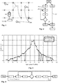
- Figure 1 illustrates a mobile device 100, which is located or moves within the coverage area of a set of access points AP 1 , ..., AP K emitting an electromagnetic signal.
- the device is equipped with receiving and measuring means, which allow the reception of the electromagnetic signal and the measuring of the signal power thereof.
- Such receiving and measuring means are well known in the art and known mobile computing devices such as smartphones or tablet computers are equipped with such means.
- a set of predetermined locations 400 is provided.
- the locations 400 as well as the positions of the access points are fixed and their positions may be stored in a database by means of 2D or 3D coordinates.
- the database can be provided on a computing device 102, on which it may accessible by the device 100 by means of a communication channel, or it may be stored on the device 100 - in which case the computing device 102 and the device 100 are the same physical entity. While the locations 400 are shown to form a grid, the locations 400 may be arbitrarily distributed in the coverage area of the access points. The locations may be spaced by about 5 meters. The distance between neighboring locations may also be less than 5 meters, as for example 1 meter.
- FIG. 2 illustrates the main steps of the method according to the invention.
- a radio map is provided, which assigns a probability value to each location 400 in the set of predetermined locations.
- Each probability value is associated with a vector of determined signal power values, wherein each vector component Pk, 1 ⁇ k ⁇ K, represents an indication of the power of the signal emitted by a given access point, as received by the device 100 in the location of measurement.
- the radio map may be provided as a look-up table or in a database structure.
- the radio map may be stored on the device 100, or it may be stored on a computing device or server 102, which is collocated with the device 100 on a communication network.
- a second step 20 an ordered series of N increasing distinct measured signal power values is provided for each one of the signals emitted by the K access points.
- the values are measured at the device 100.
- the workflow shows the steps for treating the signal emitted by one of the access points for the sake of clarity.
- the signal power values are ordered according to their magnitude by algorithms known in the art.
- the values represent the signal power values as measured by the device 100, and they may be subject to the random noise process realization described above. Together with each signal power value, a count value n is provided, which indicates how often each signal power value was measured by the device during a predetermined time period.
- the time period may be equal to about 5 seconds.
- the time period may be longer than 5 seconds.
- it may be equal to about 10 seconds.
- about one measurement per second may be provided per second for each one of the K signals emitted by the K access points.
- the signal power values, provided in -dBm, together with their respective count values may be represented by a histogram, as illustrated in Figure 3 . Due to the described measurement outages caused by power-saving routines, some of the count values may be equal to zero, while the physically available signal power at the time of measurement was in fact higher. During step 30, such erroneous zero count values, or sequences of zero count values, are detected. The erroneous count values correspond to "gaps" in the histogram, which are preceded and followed by non-empty histogram bins.
- a detected erroneous count value is corrected by interpolation.
- the non-zero value is for example set to a corrected value, which is a function of preceding and/or following non-zero count values.
- the corrected value is a function of the non-zero count values immediately preceding and following the detected gap.
- the corrected values shown as white dots, may be set so that the corrected values, the preceding and following non-zero values, each satisfy a linear function of the signal power. While other interpolation methods are feasible, this simple heuristic has provided surprisingly good results.
- the count values may be corrected so that all count values satisfy a Gaussian function.
- step 40 the method checks whether all histogram gap values have been filled. If not, steps 30 and 40 are repeated until all erroneous count values have been corrected as described. Once this is the case, a signal power value Pk is determined in step 50.
- Pk is the weighted mean of the measured distinct signal power values, each weighted by their respective corrected count values.
- N is the number of distinct measured signal power values P 1 ,..., P N
- the corrected count values are given by m 1 , ..., m N
- Steps 20 to 50 may be performed by the measuring device 100 or by the computing device or server 102, after the originally and uncorrected signal power values have been provided at the computing device 102.
- the resulting values Pk, k , 1 ⁇ k ⁇ K represent the vector which is used in step 60 to determine the location of the device 100, by means of the radio map 300. Again, this step may be performed on the mobile computing device 100 itself, or on the computing device or server 102. In the latter case, the mobile computing device 100 and the device 102 physically correspond to the same entity.
- the vector of values Pk is also referred to as a localization sample of the available signal powers.
- the location determination using the radio map is preferably performed as known in the art, for example from patent document US 2005/0243936 A1 . In a preferred embodiment, the location of the device 100 is determined as the predetermined location for which the mapping 300 indicates the highest probability based on the vector of determined signal values.
- each component Pk corresponding to access point k maps to a probability value of the device 100 being in each one of the predetermined locations. Indeed each predetermined location is specified by k signal power value probabilities. For each one of the predetermined locations, the k probability values indicated by the mapping 300 are multiplied to yield the probability of the device being in the predetermined location. This allows selecting the most probable among the predetermined locations, given the localization sample.
- the location of the device 100 is determined by selecting three or more predetermined locations for which the mapping 300 indicates the three or more highest probabilities based on the vector of determined signal power values. The position is then computed by taking the average location of said predetermined locations.
- the determined position is preferably stored for future use.
- a history of determined locations is preferably stored for each uniquely identifiable device whose position is being determined. If a determined position is unlikely with respect to previously determined locations for the same device, the determined position may preferably be rejected as being erroneous.
- the likelihood of a determined position with respect to previously determined positions may for example be expressed by an inverse of the distance between subsequently determined positions.
- Device or user movement models which are as such known in the art, may further be implemented to refine the determined location. Further, the determined location of the device may be further refined by using data made available on the device 100 by other sensing means, such as gyroscopes, GPS receivers and others.
- the determined location may be provided in absolute geographical coordinates, which facilitates a possible handover to a GPS positioning service once a line of sight to GPS satellites becomes available at the measuring device.
- the determined location may be provided in relative coordinates with respect to known reference locations, for example the predetermined locations 400 or the locations of the access points from which the electromagnetic signals are emitted.
- step 10 comprises steps that correct the measurements used for building the radio map 300.
- step 11 for the signal emitted by each access point k, an ordered series of increasing distinct signal power values is provided.
- the signal power values are measured by a device in one of the predetermined locations 400 during a predetermined time period.
- the time period may for example be a period of 60 seconds or less.
- about one measurement per second may be provided per second for each one of the K signals emitted by the K access points.
- step 12 a count value or sequence of count values, which are preceded and followed by a non-zero count value, is detected.
- the detected values are corrected using one of the methods described above in step 13. Steps 12 and 13 are repeated until all histogram gaps have been filled.
- step of correcting the count values 40 in that case further comprises:
- step 14 the resulting corrected count values are normalized so that their sum adds up to one.
- the normalized histogram value of a histogram bin represents the probability of occurrence of the corresponding signal power value.
- the resulting distributions for each access point are stored in the radio map 300 in step 15. The above steps are repeated for each one of the predetermined locations 400 until the radio map is complete.
- a plurality of radio maps 300 is generated using different types of devices. If a device intends to determine its position, it identifies its device type first, which determines the radio map that has been generated using the same device type. The corresponding radio map will be used to determine the location in step 60. Matching the device that computes the corrected localization sample vector with the measuring device that was used to build the radio map increases the accuracy of the positioning algorithm.
- the device 100 measures the signal power values using signal measuring means.
- the measurements are provided as RSSI values and stored in a memory element of the device.
- the device 100 comprises computing means such as a Central Processing Unit, CPU, which implements steps 30 to 50 as described above.
- the radio map 300 is also stored in a memory element of the device 100, so that the device may determine its location by itself. The determined location may then be used by other applications executing on the device, such as location-based services.
- the device 100 measures the signal power values using signal measuring means.
- the measurements are provided as RSSI values and stored in a memory element of the device.
- the device 100 comprises computing means such as a Central Processing Unit, CPU, which implements steps 30 to 50 as described above.
- the determined signal power values Pk are stored in a memory element of the device 100.
- the device comprises transmitting means, which allow it to transmit data to a remote computing device 102 by means of a communication channel in a communication network.
- the device transmits the determined signal power values Pk to the remote computing device, on which the radio map 300 is stored.
- the remote computing device comprises receiving means for receiving the transmitted values, a memory element and computing means which implement step 60 of the described method. Once the location of the requesting device 100 has been determined, it is transmitted from the remote computing device to the device 100 by means of communication channel.
- the device 100 measures the signal power values using signal measuring means.
- the measurements are provided as RSSI values and stored in a memory element of the device.
- the device comprises transmitting means, which allow it to transmit data to a remote computing device 102 by means of a communication channel in a communication network.
- the device transmits the measured, uncorrected signal power values to the remote computing device, which has access to the radio map 300, which may be stored on the same computing device, or on another computing device in the communication network.
- the remote computing device comprises receiving means for receiving the transmitted values, a memory element and computing means which implement steps 30 to 60 of the method according to the invention. Once the location of the requesting device 100 has been determined, it is transmitted from the remote computing device to the device 100 by means of communication channel.
- the device 100 While building the radio map 300, the device 100 measures the signal power values using signal measuring means. The measurements are provided as RSSI values and stored in a memory element of the device. The device comprises transmitting means, which allow it to transmit data to a remote computing device 102 by means of a communication channel in a communication network. The device transmits the measured, uncorrected signal power values to the remote computing device, which implements steps 11 to 15 to build the radio map. Alternatively, the device 100 implements method steps 11 to 15 and transmits the corrected values to the remote computing device. Once the remote computing device has gathered all the required information for completing the radio map, 300, the latter is stored either on the remote device, on another remote computing device, or distributed to the mobile terminal devices.
Landscapes
- Physics & Mathematics (AREA)
- Engineering & Computer Science (AREA)
- General Physics & Mathematics (AREA)
- Radar, Positioning & Navigation (AREA)
- Remote Sensing (AREA)
- Probability & Statistics with Applications (AREA)
- Mobile Radio Communication Systems (AREA)
- Position Fixing By Use Of Radio Waves (AREA)
- Computer Networks & Wireless Communication (AREA)
- Signal Processing (AREA)
Claims (15)
- Procédé destiné à déterminer la position d'un dispositif informatique mobile (100) capable de recevoir des signaux électromagnétiques à partir d'un jeu de K > 1 points d'accès (200) émettant de tels signaux et de mesurer la puissance desdits signaux par rapport à un jeu d'endroits prédéterminés ; dans lequel le procédé comprend l'étape consistant à :- fournir, à un dispositif informatique (102), un mappage (300) qui attribue une valeur de probabilité à chaque endroit (400) dans le jeu d'endroits prédéterminés, en fonction d'un vecteur de valeurs déterminées de puissance de signal ; dans lequel chaque composant vectoriel représente une indication de la puissance du signal émis par un point d'accès donné k, 1 ≤ k ≤ K, telle que reçue par le dispositif informatique mobile (100) à un endroit donné (10) ;caractérisé en ce que le procédé comprend en outre les étapes consistant à :- fournir, pour le signal émis par chaque point d'accès k, une série ordonnée de valeurs de puissance de signal distinctes croissantes telles que mesurées par le dispositif (100) à un endroit donné, conjointement avec des valeurs de comptage respectives indiquant le nombre de fois que chaque valeur de puissance de signal a été mesurée au cours d'un laps de temps prédéterminé (20) ;- pour chaque série ordonnée de valeurs, détecter une valeur de comptage ou une séquence de valeurs de comptage égales à zéro qui est précédée et suivie d'une valeur de comptage non égale à zéro (30) ;- corriger lesdites valeurs de comptage détectées pour obtenir des valeurs de comptage non égales à zéro ; dans lequel lesdites valeurs de comptage non égales à zéro sont calculées en utilisant une fonction d'interpolation de valeurs précédentes et/ou suivantes non égales à zéro (40) ;- répéter lesdites étapes (20) et (30) jusqu'à ce que chaque série ordonnée de valeurs ne comprenne aucune valeur de comptage égale à zéro, qui est précédée et suivie d'une valeur de comptage non égale à zéro ;- déterminer une valeur de puissance de signal pour le signal émis par chaque point d'accès ; dans lequel ladite valeur se base sur les séries corrigées de valeurs de comptage de puissance de signal, et fournir les valeurs de puissance de signal déterminées audit dispositif informatique (102) (50) ; et- déterminer, audit dispositif informatique (102), l'emplacement du dispositif informatique mobile (100) ; dans lequel ledit emplacement est déterminé en utilisant au moins l'emplacement prédéterminé pour lequel ledit mappage (300) indique la probabilité la plus élevée en se basant sur lesdites valeurs de puissance de signal déterminées (60).
- Procédé selon la revendication 1, dans lequel ladite étape de correction (40) comprend le réglage des valeurs de comptage détectées d'une manière telle que les valeurs de comptage précédentes et suivantes non égales à zéro et les valeurs de comptage corrigées respectent une fonction linéaire de la puissance de signal.
- Procédé selon l'une quelconque des revendications 1 ou 2, dans lequel l'étape de détermination d'une puissance de signal (50) comprend le fait de régler la puissance de signal déterminée à une moyenne pondérée des valeurs dans la série fournie de valeurs de puissance de signal mesurées ; dans lequel chaque valeur de puissance de signal est pondérée par sa valeur de comptage corrigée correspondante.
- Procédé selon l'une quelconque des revendications 1 à 3, dans lequel l'étape de détermination de la position (60) comprend l'étape supplémentaire consistant à :- sélectionner l'emplacement du dispositif de réception à titre de l'endroit prédéterminé pour lequel le mappage indique la probabilité la plus élevée en se basant sur le vecteur de valeurs de puissance de signal déterminées.
- Procédé selon l'une quelconque des revendications 1 à 3, dans lequel l'étape de détermination de la position (60) comprend l'étape supplémentaire consistant à :- sélectionner trois emplacements prédéterminés ou plus pour lesquels le mappage indique les trois probabilités les plus élevées ou plus en se basant sur le vecteur de valeurs de puissance de signal déterminées et calculer la position du dispositif de réception sous à titre de l'emplacement moyen desdits endroits prédéterminés sélectionnés.
- Procédé selon l'une quelconque des revendications 1 à 5, dans lequel l'étape (10) consistant à fournir un mappage (300) comprend les étapes supplémentaires consistant à :- fournir, à un dispositif informatique (102), pour le signal émis par chaque point d'accès, une série ordonnée de valeurs de puissance de signal distinctes croissantes telles que mesurées par un dispositif à un des endroits prédéterminés, conjointement avec des valeurs de comptage respectives indiquant le nombre de fois que chaque valeur de puissance de signal a été mesurée au cours d'un laps de temps prédéterminé (11) ;- pour chaque série ordonnée de valeurs, détecter une valeur de comptage ou une séquence de valeurs de comptage égales à zéro qui est précédée et suivie d'une valeur de comptage non égale à zéro (12) ;- corriger lesdites valeurs de comptage détectées pour obtenir des valeurs de comptage non égales à zéro ; dans lequel lesdites valeurs de comptage non égales à zéro sont calculées en utilisant une fonction d'interpolation de valeurs précédentes et/ou suivantes non égales à zéro (13) ;- répéter lesdites étapes (12) et (13) jusqu'à ce que chaque série ordonnée de valeurs ne comprenne aucune valeur de comptage égale à zéro, qui est précédée et suivie d'une valeur de comptage non égale à zéro ;- normaliser, dans chaque série, les valeurs de comptage d'une manière telle que leur somme s'additionne pour obtenir un, et d'une manière telle que chaque valeur normalisée représente la probabilité d'occurrence de la valeur de puissance de signal correspondante (14) ;- associer lesdites probabilités au point d'accès correspondant et audit endroit prédéterminé, et fournir le mappage résultant audit dispositif informatique (102) (15) ;- répéter les étapes ci-dessus pour chacun des endroits prédéterminés.
- Procédé selon la revendication 6, dans lequel ladite étape de correction (13) comprend le fait de régler les valeurs de comptage détectées d'une manière telle que les valeurs de comptage précédentes et suivantes non égales à zéro et les valeurs de comptage corrigées respectent une fonction linéaire de la puissance de signal.
- Dispositif capable de mettre en oeuvre le procédé selon l'une quelconque des revendications précédentes, le dispositif comprenant :- un élément faisant office de mémoire dans lequel au moins une série ordonnée de valeurs de puissance de signal distinctes croissantes est fournie, de manière conjointe avec des valeurs de comptage respectives indiquant le nombre de fois que chaque valeur de puissance de signal a été mesurée au cours d'un laps de temps prédéterminé par un moyen de mesure au cours d'un laps de temps prédéterminé ;- des moyens de calcul ; dans lequel lesdits moyens de calcul sont configurés pour :∘ détecter, pour chaque série ordonnée de valeurs, une valeur de comptage ou une séquence de valeurs de comptage égales à zéro qui est précédée et suivie d'une valeur de comptage non égale à zéro ;∘ corriger lesdites valeurs de comptage détectées pour obtenir des valeurs de comptage non égales à zéro qui représentent une fonction de valeurs de comptage précédentes et/ou suivantes non égales à zéro ;∘ répéter les étapes précédentes jusqu'à ce que chaque série ordonnée de valeurs ne comprenne aucune valeur de comptage égale à zéro, qui est précédée et suivie d'une valeur de comptage non égale à zéro ;∘ mémoriser lesdites séries corrigées dans l'élément faisant office de mémoire.
- Dispositif selon la revendication 8, dans lequel le dispositif comprend en outre des moyens de réception et de mesure de signaux, capables de recevoir des signaux électromagnétiques à partir d'un jeu de K > 1 points d'accès émettant de tels signaux et de mesurer la puissance desdits signaux par rapport à un jeu d'endroits prédéterminés, et dans lequel les moyens de calcul sont en outre configurés pour :- mesurer au moins une série de valeurs de puissance de signal reçues au cours d'un laps de temps prédéterminé ;- calculer, pour chaque valeur de puissance de signal distincte, les valeurs de comptage respectives indiquant le nombre de fois que chaque valeur de puissance de signal a été mesurée au cours dudit laps de temps ; et- mémoriser lesdites valeurs de puissance de signal et de comptage dans ledit élément faisant office de mémoire.
- Dispositif selon l'une quelconque des revendications 8 ou 9, dans lequel les moyens de comptage sont en outre configurés pour déterminer une valeur de puissance de signal en se basant sur chaque série corrigée de valeurs de comptage de puissance de signal.
- Dispositif selon l'une quelconque des revendications 8 à 10, dans lequel les moyens de comptage sont en outre configurés pour la mise en oeuvre de l'une quelconque des étapes opératoires selon les revendications 2 à 8.
- Dispositif selon l'une quelconque des revendications 8 à 11, dans lequel le dispositif comprend en outre des moyens de réception et de transmission de données capables de recevoir et de transmettre des données à partir d'un dispositif informatique dans un réseau de communication et dans lequel les moyens de calcul sont en outre configurés pour :- transmettre lesdites séries corrigées de valeurs à un dispositif informatique en utilisant ledit moyen de transmission de données ;- recevoir un emplacement à partir dudit dispositif informatique en utilisant ledit moyen de réception de données ; dans lequel ledit emplacement est déterminé en se basant sur lesdites séries corrigées de valeurs.
- Ordinateur capable de mettre en oeuvre le procédé selon l'une quelconque des revendications 1 à 8.
- Programme informatique comprenant des moyens de codes lisibles par ordinateur qui, lorsqu'on les exécute sur un ordinateur, font en sorte que l'ordinateur met en oeuvre le procédé selon l'une quelconque des revendications 1 à 8.
- Produit de programme informatique comprenant un support lisible par ordinateur sur lequel est stocké le programme informatique selon la revendication 14.
Priority Applications (4)
| Application Number | Priority Date | Filing Date | Title |
|---|---|---|---|
| EP13198427.0A EP2887748B1 (fr) | 2013-12-19 | 2013-12-19 | Procédé pour la détermination des emplacements intérieurs d'unités de récepteurs mobiles |
| ES13198427T ES2727483T3 (es) | 2013-12-19 | 2013-12-19 | Método para determinar ubicaciones interiores de unidades de receptores móviles |
| US15/101,173 US10156628B2 (en) | 2013-12-19 | 2014-12-17 | Method for determining indoor locations of mobile receiver units |
| PCT/EP2014/078315 WO2015091696A1 (fr) | 2013-12-19 | 2014-12-17 | Procédé de détermination d'emplacements intérieurs d'unités de réception mobiles |
Applications Claiming Priority (1)
| Application Number | Priority Date | Filing Date | Title |
|---|---|---|---|
| EP13198427.0A EP2887748B1 (fr) | 2013-12-19 | 2013-12-19 | Procédé pour la détermination des emplacements intérieurs d'unités de récepteurs mobiles |
Publications (2)
| Publication Number | Publication Date |
|---|---|
| EP2887748A1 EP2887748A1 (fr) | 2015-06-24 |
| EP2887748B1 true EP2887748B1 (fr) | 2019-03-06 |
Family
ID=49886698
Family Applications (1)
| Application Number | Title | Priority Date | Filing Date |
|---|---|---|---|
| EP13198427.0A Not-in-force EP2887748B1 (fr) | 2013-12-19 | 2013-12-19 | Procédé pour la détermination des emplacements intérieurs d'unités de récepteurs mobiles |
Country Status (4)
| Country | Link |
|---|---|
| US (1) | US10156628B2 (fr) |
| EP (1) | EP2887748B1 (fr) |
| ES (1) | ES2727483T3 (fr) |
| WO (1) | WO2015091696A1 (fr) |
Families Citing this family (3)
| Publication number | Priority date | Publication date | Assignee | Title |
|---|---|---|---|---|
| US10826630B2 (en) * | 2015-01-30 | 2020-11-03 | Rohde & Schwarz Gmbh & Co. Kg | Measuring device, system and method for wirelessly measuring radiation patterns |
| US10003989B1 (en) * | 2016-12-07 | 2018-06-19 | Rohde & Schwarz Gmbh & Co. Kg | Measuring device, measuring system and measuring method for over the air power measurement and indication |
| WO2021183613A1 (fr) * | 2020-03-12 | 2021-09-16 | Avx Antenna, Inc. D/B/A Ethertronics, Inc. | Système et procédé permettant de faire apparaître des données d'indicateur de qualite de canal (cqi) associées à une antenne multimode |
Family Cites Families (6)
| Publication number | Priority date | Publication date | Assignee | Title |
|---|---|---|---|---|
| FI114535B (fi) * | 2002-07-10 | 2004-10-29 | Ekahau Oy | Paikannustekniikka |
| US7406116B2 (en) | 2003-03-28 | 2008-07-29 | University Of Maryland | Method and system for determining user location in a wireless communication network |
| US7904097B2 (en) * | 2005-12-07 | 2011-03-08 | Ekahau Oy | Location determination techniques |
| US7616153B2 (en) * | 2006-08-04 | 2009-11-10 | Seiko Epson Corporation | Electronic device and time adjustment method |
| US9036683B2 (en) * | 2008-10-02 | 2015-05-19 | Texas Instruments Incorporated | Mitigation circuitry generating cross correlation doppler/code LAG variable comparison value |
| US9231811B2 (en) * | 2012-07-27 | 2016-01-05 | Nec Corporation | Receiver device, transmit/receive terminal, propagation delay time measurement method and computer program |
-
2013
- 2013-12-19 EP EP13198427.0A patent/EP2887748B1/fr not_active Not-in-force
- 2013-12-19 ES ES13198427T patent/ES2727483T3/es active Active
-
2014
- 2014-12-17 WO PCT/EP2014/078315 patent/WO2015091696A1/fr not_active Ceased
- 2014-12-17 US US15/101,173 patent/US10156628B2/en active Active
Non-Patent Citations (1)
| Title |
|---|
| None * |
Also Published As
| Publication number | Publication date |
|---|---|
| ES2727483T3 (es) | 2019-10-16 |
| US10156628B2 (en) | 2018-12-18 |
| US20160306025A1 (en) | 2016-10-20 |
| EP2887748A1 (fr) | 2015-06-24 |
| WO2015091696A1 (fr) | 2015-06-25 |
Similar Documents
| Publication | Publication Date | Title |
|---|---|---|
| US11067664B2 (en) | System and method for indoor localization using beacons | |
| US9933507B2 (en) | Apparatus, system and method of determining a location of a radio beacon | |
| EP3186654B1 (fr) | Procédé et appareil pour localisation basée sur mobile en temps réel, selon des mesures de capteur et de radiofréquence | |
| KR101495456B1 (ko) | 무선국의 셀프-포지셔닝 | |
| US8792387B2 (en) | System and method for effectively populating a mesh network model | |
| KR102025089B1 (ko) | Ir―uwb 측위 시스템 및 위치 측정 방법 | |
| US20110021207A1 (en) | System and Method for Estimating Positioning Error Within a WLAN-Based Positioning System | |
| Obreja et al. | Evaluation of an indoor localization solution based on bluetooth low energy beacons | |
| JP2005176386A (ja) | モバイル機器 | |
| CN103155662A (zh) | 建立信号强度简档 | |
| WO2021028049A1 (fr) | Dispositifs et procédés l'étiquetage automatique d'une localisation en intérieur de haute précision et de détermination d'informations de localisation | |
| US10156628B2 (en) | Method for determining indoor locations of mobile receiver units | |
| US10547964B2 (en) | Method and device for estimating accuracy of a position determination | |
| KR101342215B1 (ko) | Rfid를 기반으로 한 위치 측정 방법 및 시스템 | |
| KR20150115343A (ko) | 통합 측위 방법 및 장치 | |
| JP2018146484A (ja) | 情報処理装置、情報処理プログラム、及び情報処理方法 | |
| CN103698740A (zh) | 一种基于权重值选择的wifi室内定位方法 | |
| KR20190001386A (ko) | 저전력 블루투스 기반의 실내 측위 방법 및 장치 | |
| CN105393611B (zh) | 一种定位用户设备的方法、设备和系统 | |
| KR100969465B1 (ko) | 무선 센서 네트워크에서 이동노드의 위치 측정 방법 | |
| TW201140123A (en) | Locating electromagnetic signal sources | |
| US8886221B1 (en) | Mobile device location estimation using local location data | |
| KR20100071450A (ko) | 다중 스테이션 정보를 이용한 위치 측정방법 및 시스템 | |
| KR101479120B1 (ko) | pCell 데이터베이스를 이용한 오차 추정 방법과 그를 위한 장치 및 단말기 | |
| US9374676B1 (en) | Mobile communication station having selectable position latency for position estimation in a wireless network |
Legal Events
| Date | Code | Title | Description |
|---|---|---|---|
| PUAI | Public reference made under article 153(3) epc to a published international application that has entered the european phase |
Free format text: ORIGINAL CODE: 0009012 |
|
| 17P | Request for examination filed |
Effective date: 20131219 |
|
| AK | Designated contracting states |
Kind code of ref document: A1 Designated state(s): AL AT BE BG CH CY CZ DE DK EE ES FI FR GB GR HR HU IE IS IT LI LT LU LV MC MK MT NL NO PL PT RO RS SE SI SK SM TR |
|
| AX | Request for extension of the european patent |
Extension state: BA ME |
|
| R17P | Request for examination filed (corrected) |
Effective date: 20151221 |
|
| RBV | Designated contracting states (corrected) |
Designated state(s): AL AT BE BG CH CY CZ DE DK EE ES FI FR GB GR HR HU IE IS IT LI LT LU LV MC MK MT NL NO PL PT RO RS SE SI SK SM TR |
|
| RAP1 | Party data changed (applicant data changed or rights of an application transferred) |
Owner name: LUXEMBOURG INSTITUTE OF SCIENCE AND TECHNOLOGY (LI |
|
| REG | Reference to a national code |
Ref country code: DE Ref legal event code: R079 Ref document number: 602013051767 Country of ref document: DE Free format text: PREVIOUS MAIN CLASS: H04W0064000000 Ipc: G01S0005020000 |
|
| RIC1 | Information provided on ipc code assigned before grant |
Ipc: H04W 64/00 20090101ALN20180807BHEP Ipc: G01S 5/02 20100101AFI20180807BHEP |
|
| GRAP | Despatch of communication of intention to grant a patent |
Free format text: ORIGINAL CODE: EPIDOSNIGR1 |
|
| STAA | Information on the status of an ep patent application or granted ep patent |
Free format text: STATUS: GRANT OF PATENT IS INTENDED |
|
| INTG | Intention to grant announced |
Effective date: 20180926 |
|
| GRAS | Grant fee paid |
Free format text: ORIGINAL CODE: EPIDOSNIGR3 |
|
| GRAA | (expected) grant |
Free format text: ORIGINAL CODE: 0009210 |
|
| STAA | Information on the status of an ep patent application or granted ep patent |
Free format text: STATUS: THE PATENT HAS BEEN GRANTED |
|
| AK | Designated contracting states |
Kind code of ref document: B1 Designated state(s): AL AT BE BG CH CY CZ DE DK EE ES FI FR GB GR HR HU IE IS IT LI LT LU LV MC MK MT NL NO PL PT RO RS SE SI SK SM TR |
|
| REG | Reference to a national code |
Ref country code: GB Ref legal event code: FG4D |
|
| REG | Reference to a national code |
Ref country code: CH Ref legal event code: EP Ref country code: AT Ref legal event code: REF Ref document number: 1105284 Country of ref document: AT Kind code of ref document: T Effective date: 20190315 |
|
| REG | Reference to a national code |
Ref country code: DE Ref legal event code: R096 Ref document number: 602013051767 Country of ref document: DE |
|
| REG | Reference to a national code |
Ref country code: IE Ref legal event code: FG4D |
|
| REG | Reference to a national code |
Ref country code: NL Ref legal event code: FP |
|
| REG | Reference to a national code |
Ref country code: LT Ref legal event code: MG4D |
|
| PG25 | Lapsed in a contracting state [announced via postgrant information from national office to epo] |
Ref country code: LT Free format text: LAPSE BECAUSE OF FAILURE TO SUBMIT A TRANSLATION OF THE DESCRIPTION OR TO PAY THE FEE WITHIN THE PRESCRIBED TIME-LIMIT Effective date: 20190306 Ref country code: NO Free format text: LAPSE BECAUSE OF FAILURE TO SUBMIT A TRANSLATION OF THE DESCRIPTION OR TO PAY THE FEE WITHIN THE PRESCRIBED TIME-LIMIT Effective date: 20190606 Ref country code: FI Free format text: LAPSE BECAUSE OF FAILURE TO SUBMIT A TRANSLATION OF THE DESCRIPTION OR TO PAY THE FEE WITHIN THE PRESCRIBED TIME-LIMIT Effective date: 20190306 Ref country code: SE Free format text: LAPSE BECAUSE OF FAILURE TO SUBMIT A TRANSLATION OF THE DESCRIPTION OR TO PAY THE FEE WITHIN THE PRESCRIBED TIME-LIMIT Effective date: 20190306 |
|
| PG25 | Lapsed in a contracting state [announced via postgrant information from national office to epo] |
Ref country code: GR Free format text: LAPSE BECAUSE OF FAILURE TO SUBMIT A TRANSLATION OF THE DESCRIPTION OR TO PAY THE FEE WITHIN THE PRESCRIBED TIME-LIMIT Effective date: 20190607 Ref country code: RS Free format text: LAPSE BECAUSE OF FAILURE TO SUBMIT A TRANSLATION OF THE DESCRIPTION OR TO PAY THE FEE WITHIN THE PRESCRIBED TIME-LIMIT Effective date: 20190306 Ref country code: BG Free format text: LAPSE BECAUSE OF FAILURE TO SUBMIT A TRANSLATION OF THE DESCRIPTION OR TO PAY THE FEE WITHIN THE PRESCRIBED TIME-LIMIT Effective date: 20190606 Ref country code: LV Free format text: LAPSE BECAUSE OF FAILURE TO SUBMIT A TRANSLATION OF THE DESCRIPTION OR TO PAY THE FEE WITHIN THE PRESCRIBED TIME-LIMIT Effective date: 20190306 Ref country code: HR Free format text: LAPSE BECAUSE OF FAILURE TO SUBMIT A TRANSLATION OF THE DESCRIPTION OR TO PAY THE FEE WITHIN THE PRESCRIBED TIME-LIMIT Effective date: 20190306 |
|
| REG | Reference to a national code |
Ref country code: AT Ref legal event code: MK05 Ref document number: 1105284 Country of ref document: AT Kind code of ref document: T Effective date: 20190306 |
|
| REG | Reference to a national code |
Ref country code: ES Ref legal event code: FG2A Ref document number: 2727483 Country of ref document: ES Kind code of ref document: T3 Effective date: 20191016 |
|
| PG25 | Lapsed in a contracting state [announced via postgrant information from national office to epo] |
Ref country code: SK Free format text: LAPSE BECAUSE OF FAILURE TO SUBMIT A TRANSLATION OF THE DESCRIPTION OR TO PAY THE FEE WITHIN THE PRESCRIBED TIME-LIMIT Effective date: 20190306 Ref country code: EE Free format text: LAPSE BECAUSE OF FAILURE TO SUBMIT A TRANSLATION OF THE DESCRIPTION OR TO PAY THE FEE WITHIN THE PRESCRIBED TIME-LIMIT Effective date: 20190306 Ref country code: AL Free format text: LAPSE BECAUSE OF FAILURE TO SUBMIT A TRANSLATION OF THE DESCRIPTION OR TO PAY THE FEE WITHIN THE PRESCRIBED TIME-LIMIT Effective date: 20190306 Ref country code: PT Free format text: LAPSE BECAUSE OF FAILURE TO SUBMIT A TRANSLATION OF THE DESCRIPTION OR TO PAY THE FEE WITHIN THE PRESCRIBED TIME-LIMIT Effective date: 20190706 Ref country code: CZ Free format text: LAPSE BECAUSE OF FAILURE TO SUBMIT A TRANSLATION OF THE DESCRIPTION OR TO PAY THE FEE WITHIN THE PRESCRIBED TIME-LIMIT Effective date: 20190306 Ref country code: RO Free format text: LAPSE BECAUSE OF FAILURE TO SUBMIT A TRANSLATION OF THE DESCRIPTION OR TO PAY THE FEE WITHIN THE PRESCRIBED TIME-LIMIT Effective date: 20190306 |
|
| PG25 | Lapsed in a contracting state [announced via postgrant information from national office to epo] |
Ref country code: SM Free format text: LAPSE BECAUSE OF FAILURE TO SUBMIT A TRANSLATION OF THE DESCRIPTION OR TO PAY THE FEE WITHIN THE PRESCRIBED TIME-LIMIT Effective date: 20190306 Ref country code: PL Free format text: LAPSE BECAUSE OF FAILURE TO SUBMIT A TRANSLATION OF THE DESCRIPTION OR TO PAY THE FEE WITHIN THE PRESCRIBED TIME-LIMIT Effective date: 20190306 |
|
| REG | Reference to a national code |
Ref country code: DE Ref legal event code: R097 Ref document number: 602013051767 Country of ref document: DE |
|
| PG25 | Lapsed in a contracting state [announced via postgrant information from national office to epo] |
Ref country code: AT Free format text: LAPSE BECAUSE OF FAILURE TO SUBMIT A TRANSLATION OF THE DESCRIPTION OR TO PAY THE FEE WITHIN THE PRESCRIBED TIME-LIMIT Effective date: 20190306 Ref country code: IS Free format text: LAPSE BECAUSE OF FAILURE TO SUBMIT A TRANSLATION OF THE DESCRIPTION OR TO PAY THE FEE WITHIN THE PRESCRIBED TIME-LIMIT Effective date: 20190706 |
|
| PLBE | No opposition filed within time limit |
Free format text: ORIGINAL CODE: 0009261 |
|
| STAA | Information on the status of an ep patent application or granted ep patent |
Free format text: STATUS: NO OPPOSITION FILED WITHIN TIME LIMIT |
|
| PG25 | Lapsed in a contracting state [announced via postgrant information from national office to epo] |
Ref country code: DK Free format text: LAPSE BECAUSE OF FAILURE TO SUBMIT A TRANSLATION OF THE DESCRIPTION OR TO PAY THE FEE WITHIN THE PRESCRIBED TIME-LIMIT Effective date: 20190306 |
|
| 26N | No opposition filed |
Effective date: 20191209 |
|
| PG25 | Lapsed in a contracting state [announced via postgrant information from national office to epo] |
Ref country code: SI Free format text: LAPSE BECAUSE OF FAILURE TO SUBMIT A TRANSLATION OF THE DESCRIPTION OR TO PAY THE FEE WITHIN THE PRESCRIBED TIME-LIMIT Effective date: 20190306 |
|
| PG25 | Lapsed in a contracting state [announced via postgrant information from national office to epo] |
Ref country code: TR Free format text: LAPSE BECAUSE OF FAILURE TO SUBMIT A TRANSLATION OF THE DESCRIPTION OR TO PAY THE FEE WITHIN THE PRESCRIBED TIME-LIMIT Effective date: 20190306 |
|
| REG | Reference to a national code |
Ref country code: CH Ref legal event code: PL |
|
| PG25 | Lapsed in a contracting state [announced via postgrant information from national office to epo] |
Ref country code: MC Free format text: LAPSE BECAUSE OF FAILURE TO SUBMIT A TRANSLATION OF THE DESCRIPTION OR TO PAY THE FEE WITHIN THE PRESCRIBED TIME-LIMIT Effective date: 20190306 |
|
| PG25 | Lapsed in a contracting state [announced via postgrant information from national office to epo] |
Ref country code: IE Free format text: LAPSE BECAUSE OF NON-PAYMENT OF DUE FEES Effective date: 20191219 |
|
| PG25 | Lapsed in a contracting state [announced via postgrant information from national office to epo] |
Ref country code: LI Free format text: LAPSE BECAUSE OF NON-PAYMENT OF DUE FEES Effective date: 20191231 Ref country code: CH Free format text: LAPSE BECAUSE OF NON-PAYMENT OF DUE FEES Effective date: 20191231 |
|
| PG25 | Lapsed in a contracting state [announced via postgrant information from national office to epo] |
Ref country code: CY Free format text: LAPSE BECAUSE OF FAILURE TO SUBMIT A TRANSLATION OF THE DESCRIPTION OR TO PAY THE FEE WITHIN THE PRESCRIBED TIME-LIMIT Effective date: 20190306 |
|
| PG25 | Lapsed in a contracting state [announced via postgrant information from national office to epo] |
Ref country code: HU Free format text: LAPSE BECAUSE OF FAILURE TO SUBMIT A TRANSLATION OF THE DESCRIPTION OR TO PAY THE FEE WITHIN THE PRESCRIBED TIME-LIMIT; INVALID AB INITIO Effective date: 20131219 Ref country code: MT Free format text: LAPSE BECAUSE OF FAILURE TO SUBMIT A TRANSLATION OF THE DESCRIPTION OR TO PAY THE FEE WITHIN THE PRESCRIBED TIME-LIMIT Effective date: 20190306 |
|
| PG25 | Lapsed in a contracting state [announced via postgrant information from national office to epo] |
Ref country code: MK Free format text: LAPSE BECAUSE OF FAILURE TO SUBMIT A TRANSLATION OF THE DESCRIPTION OR TO PAY THE FEE WITHIN THE PRESCRIBED TIME-LIMIT Effective date: 20190306 |
|
| PGFP | Annual fee paid to national office [announced via postgrant information from national office to epo] |
Ref country code: LU Payment date: 20221213 Year of fee payment: 10 Ref country code: GB Payment date: 20221201 Year of fee payment: 10 Ref country code: FR Payment date: 20221213 Year of fee payment: 10 Ref country code: DE Payment date: 20221214 Year of fee payment: 10 |
|
| PGFP | Annual fee paid to national office [announced via postgrant information from national office to epo] |
Ref country code: BE Payment date: 20221213 Year of fee payment: 10 |
|
| PGFP | Annual fee paid to national office [announced via postgrant information from national office to epo] |
Ref country code: ES Payment date: 20230103 Year of fee payment: 10 |
|
| PGFP | Annual fee paid to national office [announced via postgrant information from national office to epo] |
Ref country code: IT Payment date: 20221222 Year of fee payment: 10 |
|
| PGFP | Annual fee paid to national office [announced via postgrant information from national office to epo] |
Ref country code: NL Payment date: 20230113 Year of fee payment: 10 |
|
| REG | Reference to a national code |
Ref country code: DE Ref legal event code: R119 Ref document number: 602013051767 Country of ref document: DE |
|
| REG | Reference to a national code |
Ref country code: NL Ref legal event code: MM Effective date: 20240101 |
|
| PG25 | Lapsed in a contracting state [announced via postgrant information from national office to epo] |
Ref country code: LU Free format text: LAPSE BECAUSE OF NON-PAYMENT OF DUE FEES Effective date: 20231219 |
|
| GBPC | Gb: european patent ceased through non-payment of renewal fee |
Effective date: 20231219 |
|
| REG | Reference to a national code |
Ref country code: BE Ref legal event code: MM Effective date: 20231231 |
|
| PG25 | Lapsed in a contracting state [announced via postgrant information from national office to epo] |
Ref country code: LU Free format text: LAPSE BECAUSE OF NON-PAYMENT OF DUE FEES Effective date: 20231219 |
|
| PG25 | Lapsed in a contracting state [announced via postgrant information from national office to epo] |
Ref country code: NL Free format text: LAPSE BECAUSE OF NON-PAYMENT OF DUE FEES Effective date: 20240101 |
|
| PG25 | Lapsed in a contracting state [announced via postgrant information from national office to epo] |
Ref country code: NL Free format text: LAPSE BECAUSE OF NON-PAYMENT OF DUE FEES Effective date: 20240101 |
|
| PG25 | Lapsed in a contracting state [announced via postgrant information from national office to epo] |
Ref country code: DE Free format text: LAPSE BECAUSE OF NON-PAYMENT OF DUE FEES Effective date: 20240702 |
|
| PG25 | Lapsed in a contracting state [announced via postgrant information from national office to epo] |
Ref country code: GB Free format text: LAPSE BECAUSE OF NON-PAYMENT OF DUE FEES Effective date: 20231219 |
|
| PG25 | Lapsed in a contracting state [announced via postgrant information from national office to epo] |
Ref country code: BE Free format text: LAPSE BECAUSE OF NON-PAYMENT OF DUE FEES Effective date: 20231231 |
|
| PG25 | Lapsed in a contracting state [announced via postgrant information from national office to epo] |
Ref country code: FR Free format text: LAPSE BECAUSE OF NON-PAYMENT OF DUE FEES Effective date: 20231231 |
|
| PG25 | Lapsed in a contracting state [announced via postgrant information from national office to epo] |
Ref country code: GB Free format text: LAPSE BECAUSE OF NON-PAYMENT OF DUE FEES Effective date: 20231219 Ref country code: FR Free format text: LAPSE BECAUSE OF NON-PAYMENT OF DUE FEES Effective date: 20231231 Ref country code: DE Free format text: LAPSE BECAUSE OF NON-PAYMENT OF DUE FEES Effective date: 20240702 Ref country code: BE Free format text: LAPSE BECAUSE OF NON-PAYMENT OF DUE FEES Effective date: 20231231 |
|
| REG | Reference to a national code |
Ref country code: ES Ref legal event code: FD2A Effective date: 20250131 |
|
| PG25 | Lapsed in a contracting state [announced via postgrant information from national office to epo] |
Ref country code: ES Free format text: LAPSE BECAUSE OF NON-PAYMENT OF DUE FEES Effective date: 20231220 |
|
| PG25 | Lapsed in a contracting state [announced via postgrant information from national office to epo] |
Ref country code: IT Free format text: LAPSE BECAUSE OF NON-PAYMENT OF DUE FEES Effective date: 20231219 |