EP2887992B1 - Mandrin mit zusammengesetzter form für drehmomentübertragung - Google Patents
Mandrin mit zusammengesetzter form für drehmomentübertragung Download PDFInfo
- Publication number
- EP2887992B1 EP2887992B1 EP13712663.7A EP13712663A EP2887992B1 EP 2887992 B1 EP2887992 B1 EP 2887992B1 EP 13712663 A EP13712663 A EP 13712663A EP 2887992 B1 EP2887992 B1 EP 2887992B1
- Authority
- EP
- European Patent Office
- Prior art keywords
- lead
- stylet
- medical
- inner member
- feature
- Prior art date
- Legal status (The legal status is an assumption and is not a legal conclusion. Google has not performed a legal analysis and makes no representation as to the accuracy of the status listed.)
- Active
Links
- 230000005540 biological transmission Effects 0.000 title 1
- 238000004873 anchoring Methods 0.000 claims description 30
- 230000008878 coupling Effects 0.000 claims description 27
- 238000010168 coupling process Methods 0.000 claims description 27
- 238000005859 coupling reaction Methods 0.000 claims description 27
- 230000000747 cardiac effect Effects 0.000 claims description 14
- 239000007943 implant Substances 0.000 claims description 11
- PXHVJJICTQNCMI-UHFFFAOYSA-N Nickel Chemical compound [Ni] PXHVJJICTQNCMI-UHFFFAOYSA-N 0.000 claims description 10
- 229920000642 polymer Polymers 0.000 claims description 8
- 229910001220 stainless steel Inorganic materials 0.000 claims description 7
- 239000010935 stainless steel Substances 0.000 claims description 7
- 229910000831 Steel Inorganic materials 0.000 claims description 5
- RTAQQCXQSZGOHL-UHFFFAOYSA-N Titanium Chemical compound [Ti] RTAQQCXQSZGOHL-UHFFFAOYSA-N 0.000 claims description 5
- 229910052759 nickel Inorganic materials 0.000 claims description 5
- 239000010959 steel Substances 0.000 claims description 5
- 229910052719 titanium Inorganic materials 0.000 claims description 5
- 239000010936 titanium Substances 0.000 claims description 5
- 229910000531 Co alloy Inorganic materials 0.000 claims description 4
- QXZUUHYBWMWJHK-UHFFFAOYSA-N [Co].[Ni] Chemical compound [Co].[Ni] QXZUUHYBWMWJHK-UHFFFAOYSA-N 0.000 claims description 4
- 210000004375 bundle of his Anatomy 0.000 claims description 4
- 210000002837 heart atrium Anatomy 0.000 claims description 4
- 238000000034 method Methods 0.000 description 12
- 210000001519 tissue Anatomy 0.000 description 8
- 150000001875 compounds Chemical class 0.000 description 5
- 238000007726 management method Methods 0.000 description 5
- 229910001000 nickel titanium Inorganic materials 0.000 description 5
- 230000033764 rhythmic process Effects 0.000 description 5
- -1 for example Inorganic materials 0.000 description 4
- 239000000463 material Substances 0.000 description 3
- HLXZNVUGXRDIFK-UHFFFAOYSA-N nickel titanium Chemical compound [Ti].[Ti].[Ti].[Ti].[Ti].[Ti].[Ti].[Ti].[Ti].[Ti].[Ti].[Ni].[Ni].[Ni].[Ni].[Ni].[Ni].[Ni].[Ni].[Ni].[Ni].[Ni].[Ni].[Ni].[Ni] HLXZNVUGXRDIFK-UHFFFAOYSA-N 0.000 description 3
- 210000005245 right atrium Anatomy 0.000 description 3
- 210000005241 right ventricle Anatomy 0.000 description 3
- 230000000638 stimulation Effects 0.000 description 3
- 229910000851 Alloy steel Inorganic materials 0.000 description 2
- 229910000990 Ni alloy Inorganic materials 0.000 description 2
- 239000004696 Poly ether ether ketone Substances 0.000 description 2
- 239000004952 Polyamide Substances 0.000 description 2
- 229910001069 Ti alloy Inorganic materials 0.000 description 2
- JUPQTSLXMOCDHR-UHFFFAOYSA-N benzene-1,4-diol;bis(4-fluorophenyl)methanone Chemical compound OC1=CC=C(O)C=C1.C1=CC(F)=CC=C1C(=O)C1=CC=C(F)C=C1 JUPQTSLXMOCDHR-UHFFFAOYSA-N 0.000 description 2
- 238000010586 diagram Methods 0.000 description 2
- 210000001174 endocardium Anatomy 0.000 description 2
- 238000012986 modification Methods 0.000 description 2
- 230000004048 modification Effects 0.000 description 2
- 210000004165 myocardium Anatomy 0.000 description 2
- 229920002647 polyamide Polymers 0.000 description 2
- 229920002530 polyetherether ketone Polymers 0.000 description 2
- 229920001296 polysiloxane Polymers 0.000 description 2
- 230000004936 stimulating effect Effects 0.000 description 2
- 238000012546 transfer Methods 0.000 description 2
- 238000013519 translation Methods 0.000 description 2
- 230000001746 atrial effect Effects 0.000 description 1
- 210000001992 atrioventricular node Anatomy 0.000 description 1
- 238000009125 cardiac resynchronization therapy Methods 0.000 description 1
- 238000004891 communication Methods 0.000 description 1
- 230000007423 decrease Effects 0.000 description 1
- 230000001419 dependent effect Effects 0.000 description 1
- 230000000694 effects Effects 0.000 description 1
- 210000005003 heart tissue Anatomy 0.000 description 1
- 238000002513 implantation Methods 0.000 description 1
- 238000003780 insertion Methods 0.000 description 1
- 230000037431 insertion Effects 0.000 description 1
- 210000005246 left atrium Anatomy 0.000 description 1
- 210000005240 left ventricle Anatomy 0.000 description 1
- 229910052751 metal Inorganic materials 0.000 description 1
- 239000002184 metal Substances 0.000 description 1
- 210000000278 spinal cord Anatomy 0.000 description 1
- 230000002792 vascular Effects 0.000 description 1
- 210000005166 vasculature Anatomy 0.000 description 1
- 210000003462 vein Anatomy 0.000 description 1
- 230000002861 ventricular Effects 0.000 description 1
Images


Classifications
-
- A—HUMAN NECESSITIES
- A61—MEDICAL OR VETERINARY SCIENCE; HYGIENE
- A61N—ELECTROTHERAPY; MAGNETOTHERAPY; RADIATION THERAPY; ULTRASOUND THERAPY
- A61N1/00—Electrotherapy; Circuits therefor
- A61N1/02—Details
- A61N1/04—Electrodes
- A61N1/05—Electrodes for implantation or insertion into the body, e.g. heart electrode
- A61N1/056—Transvascular endocardial electrode systems
-
- A—HUMAN NECESSITIES
- A61—MEDICAL OR VETERINARY SCIENCE; HYGIENE
- A61N—ELECTROTHERAPY; MAGNETOTHERAPY; RADIATION THERAPY; ULTRASOUND THERAPY
- A61N1/00—Electrotherapy; Circuits therefor
- A61N1/02—Details
- A61N1/04—Electrodes
- A61N1/05—Electrodes for implantation or insertion into the body, e.g. heart electrode
- A61N1/0587—Epicardial electrode systems; Endocardial electrodes piercing the pericardium
- A61N1/0592—Introducing the lead through the pericardium with a needle
-
- A—HUMAN NECESSITIES
- A61—MEDICAL OR VETERINARY SCIENCE; HYGIENE
- A61N—ELECTROTHERAPY; MAGNETOTHERAPY; RADIATION THERAPY; ULTRASOUND THERAPY
- A61N1/00—Electrotherapy; Circuits therefor
- A61N1/02—Details
- A61N1/04—Electrodes
- A61N1/05—Electrodes for implantation or insertion into the body, e.g. heart electrode
- A61N1/0551—Spinal or peripheral nerve electrodes
-
- A—HUMAN NECESSITIES
- A61—MEDICAL OR VETERINARY SCIENCE; HYGIENE
- A61N—ELECTROTHERAPY; MAGNETOTHERAPY; RADIATION THERAPY; ULTRASOUND THERAPY
- A61N1/00—Electrotherapy; Circuits therefor
- A61N1/18—Applying electric currents by contact electrodes
- A61N1/32—Applying electric currents by contact electrodes alternating or intermittent currents
- A61N1/36—Applying electric currents by contact electrodes alternating or intermittent currents for stimulation
- A61N1/3605—Implantable neurostimulators for stimulating central or peripheral nerve system
-
- A—HUMAN NECESSITIES
- A61—MEDICAL OR VETERINARY SCIENCE; HYGIENE
- A61N—ELECTROTHERAPY; MAGNETOTHERAPY; RADIATION THERAPY; ULTRASOUND THERAPY
- A61N1/00—Electrotherapy; Circuits therefor
- A61N1/18—Applying electric currents by contact electrodes
- A61N1/32—Applying electric currents by contact electrodes alternating or intermittent currents
- A61N1/36—Applying electric currents by contact electrodes alternating or intermittent currents for stimulation
- A61N1/362—Heart stimulators
-
- A—HUMAN NECESSITIES
- A61—MEDICAL OR VETERINARY SCIENCE; HYGIENE
- A61N—ELECTROTHERAPY; MAGNETOTHERAPY; RADIATION THERAPY; ULTRASOUND THERAPY
- A61N1/00—Electrotherapy; Circuits therefor
- A61N1/02—Details
- A61N1/04—Electrodes
- A61N1/05—Electrodes for implantation or insertion into the body, e.g. heart electrode
- A61N1/056—Transvascular endocardial electrode systems
- A61N1/057—Anchoring means; Means for fixing the head inside the heart
- A61N2001/058—Fixing tools
Definitions
- the present disclosure relates to a medical stylet. More specifically, the invention relates to a pre-shaped stylet for implanting a lead in the heart of a patient and for delivering torque to a distal lead feature.
- Implantable medical leads can be used to deliver electrical stimulation to the body tissue through implantable medical devices.
- implantable devices include cardiac rhythm management (CRM) systems (e.g., pacemakers, defibrillators, and cardiac resynchronization therapy devices) and neurostimulation systems (e.g., spinal cord stimulation (SCS) systems).
- CRM cardiac rhythm management
- the medical leads typically extend intravascularly to an implant location within or on a patient's heart.
- the implantable medical leads can be equipped with at least one electrode.
- the implantable medical leads are often positioned so that the electrode delivers electrical stimulation to a target tissue without stimulating adjacent tissue.
- the implantable medical leads can be flexible and can require use of a support device (e.g., a stylet) to effectively guide the implantable medical lead into a desired location inside the heart of a patient.
- a support device e.g., a stylet
- a stylet-driven implantable medical lead can have a pre-formed shape to facilitate advancement of the medical lead to certain locations within the heart.
- Implantable medical leads are often anchored or fixed to heart tissue using an active (i.e., movable or deployable) fixation anchor, such as a rotatable helix, located at or near a distal end of the lead.
- an active fixation anchor such as a rotatable helix
- the medical leads are typically flexible in torsion, it can be a challenge to use the lead body to rotate the helix.
- the stylet can operate to deliver torque from a proximal end of the lead to an active fixation mechanism at or near the distal end of the lead.
- US 4,381,013 A discloses a medical stylet for use in delivering and anchoring an implantable medical lead.
- the invention provides a medical stylet for use in delivering and anchoring an implantable medical lead according to claim 1.
- Preferred embodiments are defined in the dependent claims.
- the methods disclosed herein do not form part of the invention. The same applies to all other embodiments, aspects and examples herein that do not fall under the scope of claim 1.
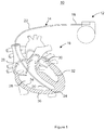
- FIG. 1 is a perspective view of an implantable cardiac rhythm management (CRM) system 10.
- the system 10 includes an implantable rhythm management device 12 and an implantable lead 14, which extends from a proximal end portion 18 to a distal end portion 20.
- the heart 16 includes a right atrium 26, a right ventricle 28, a left atrium 30, and a left ventricle 32.
- the heart 16 includes an endocardium 34 covering the myocardium 36.
- an anchoring mechanism e.g., a fixation helix
- 24 located at the distal end portion 20 of the lead 14 penetrates through the endocardium 34 and is embedded in the myocardium 36.
- the anchoring mechanism 24 is electrically active and thus, operates as a helical electrode for sensing the electrical activity of the heart 16 and/or applying a stimulating pulse to the right ventricle 28.
- the anchoring mechanism 24 includes a coupling feature for coupling with a stylet and a fixation feature for engaging and anchoring with tissue in or near the heart 16.
- the CRM system 10 includes a plurality of leads similar to the lead 14.
- first lead can be similar to the lead 14 adapted to convey electrical signals between the pulse generator (which can be the implantable rhythm management device) 12 and the right ventricle 28 and a second lead (not shown) adapted to convey electrical signals between the pulse generator 12 and the right atrium 26 or coronary veins (not shown).
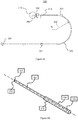
- FIGS. 2A-2C show various view and portions of a stylet 300 for assisting with delivery of the lead 14 to a desired location within or near the patient's heart.
- the stylet 300 includes an inner elongate member 302, an outer elongate member 304, and an actuating mechanism 326.
- the inner member 302 and outer member 304 are sized and shaped such that the inner member 302 can be disposed within the outer member 304, in such a manner that the inner member 302 can be translated and rotated within the outer member 304.
- This translation and rotation can be accomplished by the actuating mechanism 326 in various embodiments.
- the stylet 300 does not include an actuation mechanism 326. In these embodiments, this translation and rotation can be accomplished directly by a user (e.g., a physician) manipulating one or both of the inner member 302 and the outer member 304.
- the stylet 300 has a length defined by the length of the inner member 302, which has a length greater than a corresponding length of the outer member 304. As shown, the length of the inner member 302 exceeds the length of the outer member 304 by a distance "D."
- the inner member 302 includes a distal tip portion 306, which extends beyond a distal portion 312 of the outer member 304.
- the length of the medical stylet 300 is selected based on a corresponding length of the lead 14 that the stylet will be used to help implant. For example, the stylet 300 can have a sufficient length to extend from proximal to a lead proximal end to a location at or near a distal end of the lead.
- the length of the stylet 300 is between about 400 mm and about 600 mm. More specifically, in certain embodiments, the length of the stylet 300 is one of 450 mm, 520 mm, 580 mm, and 590 mm. In various embodiments, the distance "D" is between about 1 mm and about 20 mm.
- the inner member 302 has an outer diameter of between about 0.0040 inches (0.1016 mm) and 0.0100 inches (0.254 mm), and the outer member 304 has an outer diameter of between about 0.0050 inches (0.127 mm) and about 0.0250 inches (0.635 mm). In some embodiments, the outer diameter of the inner member 302 is 0.0080 inches (0.2032 mm), and the outer diameter of the outer member 304 is 0.017 inches (0.4318 mm).
- the implantable lead 14 including a silicone lead body, which is generally flexible and not configured to have a predetermined shape.
- the implantable lead 14 can be configured for placement in a variety of locations in or near the heart 16, including the atrial wall, the ventricular wall, the septal wall, or a location at or near the bundle of His (located at or near the atrioventricular node).
- the lead body is often made from a soft, silicone material
- a stylet 300 having a preset or predetermined shape.
- the lead Upon placing such a stylet within a lumen of the implantable lead, the lead will conform to the shape of the stylet 300.
- the stylet 300 is preformed, as further explained below, with a curved distal portion 320 having a radius of curvature 322.
- the outer member 304 includes an inner lumen extending along its length. The lumen is sized to accept the inner member 302 to form the stylet 300.
- the outer member 304 of the medical stylet 300 is formed of sufficiently stiff material to allow the outer member 304 to hold a predetermined shape.
- the outer member 304 is made from one or more of a steel, steel alloy (including, for example, stainless steel) titanium, titanium alloys, nickel, nickel alloy, nickel-titanium alloy (including, for example, Nitinol and MP35N), or a polymer (e.g., PEEK or polyamide).
- the outer member 304 is made from a stainless steel or a nickel cobalt alloy.
- the second elongate member 304 is configured to have a predefined J-shape, wherein the J-shape is selected to allow the lead 14 to be placed at a desired location in or near the heart 16.
- the outer member 304 has a distal curved portion having a radius of curvature 322 of between about 0.40 and 0.50 inches (10.16 and 12.7 mm). This radius of curvature can be selected to direct a distal portion of the implantable lead 14 to a desired location in the atrium.
- the curved portion is configured with a predetermined wider curve, or with an L-shape, for example to assist in directing a distal portion of the implantable lead to a location near the bundle of His.
- the inner member 302 of the stylet 300 includes a distal tip portion 306, which is configured to engage with a portion of the implantable lead 14. By engaging appropriately with a distal portion of the implantable lead, the stylet can operate to transmit a torque from a proximal end of the stylet to a component of the implantable lead.
- the inner member 302 can be configured to be substantially straight along its length and to have a substantially circular cross-section. The substantially straight shape of the first elongate member 302 facilitates delivery of torque along its length and ultimately to a component of the lead 14 to which it is rotationally coupled.
- the inner member 302 is made of a material having torsional stiffness.
- the inner member 302 is made from one or more of a steel, steel alloy (including, for example, stainless steel) titanium, titanium alloys, nickel, nickel alloy, nickel-titanium alloy (including, for example, Nitinol and MP35N), or a polymer (e.g., PEEK or polyamide).
- the distal tip portion 306 of the inner member 302 is formed of a polymer and the remaining length is formed of stainless steel or Nitinol.
- the distal tip portion 306 is formed of a metal and the remaining length of the inner member 302 is formed of a polymer.
- the inner member 302 may be formed as a tube, a wire, a cable, a coil, or any combination of these elements.
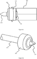
- FIG. 2B is a perspective view of the tip portion 306 of the inner member 302 extending from the proximal portion 312 of the second elongate member 304.
- the tip portion 306 includes a tip feature 310.
- This feature 310 can function to both facilitate engagement with a corresponding lead feature and to transfer torque from the inner member 302 to a corresponding lead feature.
- the tip feature 310 can be any shape capable of engaging with a corresponding shape on a lead feature, including, for example, a flat face, a triangular sectional shape, a square sectional shape, a star sectional shape, a hex sectional shape, a star shape (e.g., a Torx® profile), or other custom shape capable of transferring torque.
- the specific dimensions of the feature 310 are selected to provide a close (e.g., interference) fit with a corresponding feature on the component of the lead 14.
- FIG. 2C shows an exemplary tip portion 306 of the inner member 302 of the medical stylet 300.
- the tip portion 306 includes a proximal portion 328 and a distal portion 330.
- the tip portion 306 can include a length 340 extending from the proximal portion 328 to the distal portion 330.
- the length 340 can vary from 0.04 inches (1.016 mm) to 0.08 inches (2.032 mm). In some embodiments, the length 340 can be 0.06 inches (1.524 mm).
- the tip portion 306 can be configured to include a first swage point 338 along a plane 344.
- the first swage point 338 can be defined and configured so that the proximal portion 328 forms a first swage angle 350 ( ⁇ ) with the distal portion 330.
- the first swage point 338 can be the point where the proximal portion 328 meets the distal portion 330.
- the proximal portion 328 can be configured to be substantially straight.
- the tip portion 306 can be configured to define a second swage point 348 along a plane 346.
- the second swage point 348 can be defined and configured so that the proximal portion 328 forms a second swage angle 352 ( ⁇ ) with the distal portion 330.
- the second swage point 348 can define the point where the tip portion 306 meets other components of the first elongate member 302.
- the tip portion 306 can be configured so that the first swage angle 350 ( ⁇ ) can be substantially opposite to the second swage angle 352 ( ⁇ ).
- the first swage point 338, the first swage angle 350 ( ⁇ ), the second swage point 348, or the second swage angle 352 ( ⁇ ) can be positioned or configured so as to allow various shapes to be designed for the tip portion 306 such as to facilitate fixation of the tip portion 306 to the coupler 356 of the lead 14 for lead torque delivery or lead implantation.
- the tip feature 310 can be configured to have one of bladed, triangular cut, square cut, Philips, Torx®, hex, or any other custom keyed head for easy fixation with the coupler 356 placed inside the lead 14.
- the distal portion 330 of the tip portion 306 can be configured to define a width 342.
- the width 342 can be configured so that it decreases along the direction A1 starting from the first swage point 338 or the second swage point 348, and extending until an end point 354 located on the distal portion 330.
- the width 342 can vary between 0.005 inches (0.127 mm) and 0.009 inches (0.2286 mm).
- the width 342 can be 0.007 inches (0.1778 mm) at end point 354.
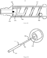
- FIG. 3A is a sectional view of components of an anchoring mechanism (e.g., a fixation helix) 24 of an implantable medical lead 14.
- the anchoring mechanism 24 is typically coupled at or near a distal end of the medical lead 14, and it operates to help anchor or secure the lead 14 at a desired location in or near the patient's heart.
- the anchoring mechanism 24 includes a housing 402 and a rotatable helical member (i.e., fixation feature) 406.
- the housing 402 and helical member 406 are configured such that upon rotation of the helical member, it will advance forward such that it extends from a distal end or the housing 402.
- the helical member 406 may extend into and engage tissue to perform an anchoring function.
- the housing 402 is active such that it operates as an electrode.
- an internal surface of the housing 402 is lined with a polymer liner 407 to prevent electrical communication between the housing and the helical member.
- the housing 402 further includes a peg, which holds the helical member 406 in place and allows the helical member 406 to extend from the housing 402 only upon rotation.
- the helical member 406 includes a structure 410 having coupling feature 418.
- the coupling feature 418 is configured to couple with the tip feature 310 of the inner member 302 in such a manner as to allow torque to transfer from the inner member 302 to the coupling feature 418. This torque will then operate to encourage rotation of the helical member 406.
- FIG. 3B shows the tip portion 306 of the inner member 302 extending from a distal portion of the outer member 304, according to other embodiments.
- the distal tip feature 310 (not shown) is coupled or mated with the coupling feature 418 of the implantable lead 14.
- the stylet 300 can be used to deliver torque to the lead feature by rotating the inner member 302.
- the inner member 302 is configured to have a torsional stiffness sufficient to deliver a torque input at the proximal end, along its length to the distal end to the anchoring mechanism (e.g., fixation helix) 24, with less than 360 degrees rotation (i.e., twisting) along the length of the inner member 302 (i.e., between the proximal end and the distal end).
- the inner member 302 has a torsional stiffness sufficient to deliver a torque to the fixation helix, with less than 360 degrees rotation along its length, in an amount in the range between about 10 and about 250 micronewton-meters.
- the inner member 302 has a torsional stiffness sufficient to deliver a torque to the fixation helix with less than 360 degrees rotation along its length, in an amount in the range between about 20 and about 100 micronewton-meters. In further embodiments, the inner member 302 has a torsional stiffness sufficient to deliver a torque to the fixation helix, with less than 360 degrees rotation along its length, in an amount in the range between about 30 and about 80 micronewton-meters. In further embodiments, the inner member 302 has a torsional stiffness sufficient to deliver a torque to the fixation helix, with less than 360 degrees rotation along its length, in an amount of at least about 40 micronewton-meters. According to various embodiments, the inner member 302 has sufficient torsional stiffness to deliver a torque to the fixation helix, with less than 24 degrees or rotation along its length, in any of the various amounts set forth above.
- FIGS. 4A and 4B show further embodiments of a stylet 300.
- the distal end portion 306 of the inner member 302 has a diameter larger than an inner diameter of the outer member 304.
- the end portion 306 is prevented from moving longitudinally into the lumen of the outer member 304. In this manner, the inner member 302 is restricted from moving longitudinally with respect to the outer member 304, but remains free to rotate with respect to the outer member 304.
- the mechanism can be operated to provide relative longitudinal and/or rotational movement between the inner member 302 and the outer member 304.
- the mechanism 326 is configured to advance the inner member 302 with respect to the outer member 304, so as to engage with the lead 14.
- the actuating mechanism 326 can be configured to actuate and move the inner member 302 back and forth within the lumen 316 of the outer member 304, for example, toward the coupling feature 418 of the lead 14.
- the actuating mechanism 326 can further be configured to retract the inner member 302 back into the lumen 316 after implant of the lead 14 at the desired implant location.
- the actuating mechanism 326 is coupled at the proximal end portion of the outer member 304. In other embodiments, the actuating mechanism 326 is operatively coupled to the inner member 302. In various embodiments, the actuating mechanism 326 can be a handle or a knob wherein rotating the handle or the knob can cause the inner member 302 to rotate and engage with the coupling feature 418 of the lead 14. In some embodiments, the actuating mechanism 326 can be a push button or a piston type arrangement that allows the movement of the inner member 302 forward and backward in order to engage with the lead 14.
- the stylet 300 can be inserted into the longitudinally extending lumen of the lead 14.
- the stylet 300 can be inserted such that the distal tip feature 310 engages the coupling feature 418 at or near a distal end of the lead 14.
- the outer member 304 of the stylet 300 imparts (wholly or partially) its predetermined shape onto the flexible lead body, such that the lead 14 may be effectively advanced through the patient's vasculature and directed to a desired implant location or site.
- the outer member 304 imparts a J-shape upon the lead 14.
- the J-shape of the outer member 304 of the medical stylet 300 allows the lead 14 to be placed in the right atrium 26 of the heart 16.
- the user Upon reaching the desired implant location near or in the patient's heart, the user (e.g., a physician) imparts a torque upon the inner member 302. This torque is then transferred by the distal tip feature 310 from the inner member 302 to coupling feature 418 on the lead. This torque causes rotation of the helical component, which then advances into and engages the tissue in or near the heart.
- FIG. 5 is a perspective view of a compound-shaped medical stylet 600 for imparting a shape to the lead 14 and for delivering torque to a distal anchoring mechanism of the lead 14.
- the compound shaped medical stylet 600 can be configured to have more than one curve to provide a compound shape to the lead 14.
- the compound shaped medical stylet 600 includes an inner member 608, an outer member 610, and an actuating mechanism 612.
- the inner member 608 can be similar to the inner member 302 in structure and function.
- the outer member 610 can be similar to the outer member 304 in structure and function.
- the actuating mechanism 612 can be similar to the actuating mechanism 326 in structure and function.
- the inner member 608 can include a distal end portion 618 and a proximal end portion 620.
- the outer member 610 can include a distal end portion 614 and a proximal end portion 616.
- the compound shaped medical stylet 600 can be configured so that the outer member 610, the proximal end portion 620, and the actuating mechanism 612 lie in a first plane 602.
- the distal end portion 618 of the first elongate member 608 can be configured to lie in a second plane 606 that is different from the first plane 602.
- the compound-shaped medical stylet 600 is configured so that the outer member 610 defines a curve shape 604 in the plane 606.
- the outer member 610 of the stylet 600 is configured to have a pre-defined shape, wherein the pre-defined shape can be a multi-planar shape.
- the medical stylet 600 is configured and shaped to be defined along more than two planes so as to provide a multi-planar shape to the compound-shaped medical stylet 600.
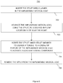
- FIG. 6 is a flowchart illustrating a method 700 of placing the lead 14 in the heart 16 using a medical stylet 300 or 600.
- the method 700 can include inserting the medical stylet that can be similar to the medical stylet 300 or the medical stylet 600 into the lumen 22 defined by the lead 14 in order to provide the desired shape to the lead 14 as illustrated at step 702.
- the medical stylet 300 or the medical stylet 600 can be configured to include a first elongate member and a second elongate member for at least partially enclosing the first elongate member; the second elongate member can be configured for providing a shape to the lead 14 in accordance with an anatomical passageway.
- the medical stylet can be similar to the medical stylet 300 or the compound shaped medical stylet 600.
- the second elongate member such as the second elongate member 304 of the stylet such as for example, the medical stylet 300 can be a pre-shaped member that can be configured to allow a shape to be provided to the lead 14, in accordance with the anatomical passageway.
- the method 700 can further include rotating the medical stylet 300 to cause the first elongate member similar to the first elongate member 302 to engage with the lead 14 to provide torque externally at step 704.
- rotating the medical stylet 300 can cause the tip portion 310 of the first elongate member 302 to engage with the lead 14 to externally provide torque to the lead 14.
- the tip portion 310 of the first elongate member 302 can be configured in different shapes, in accordance with the coupler 356 used in the lead 14.
- the method 700 can further include guiding the medical stylet 300 along the anatomical passageway to cause the placement of the lead 14 at step 706.
- the method 700 can include retracting the medical stylet 300 after placing the lead 14 at the anatomical location.
Landscapes
- Health & Medical Sciences (AREA)
- Heart & Thoracic Surgery (AREA)
- Nuclear Medicine, Radiotherapy & Molecular Imaging (AREA)
- Cardiology (AREA)
- Engineering & Computer Science (AREA)
- Biomedical Technology (AREA)
- Radiology & Medical Imaging (AREA)
- Life Sciences & Earth Sciences (AREA)
- Animal Behavior & Ethology (AREA)
- General Health & Medical Sciences (AREA)
- Public Health (AREA)
- Veterinary Medicine (AREA)
- Vascular Medicine (AREA)
- Electrotherapy Devices (AREA)
Claims (11)
- Medizinischer Mandrin (300) zur Verwendung bei der Zuführung und Verankerung einer implantierbaren medizinischen Leitung (14) zu einem gewünschten Ort nahe des oder in dem Herzen eines Patienten, welcher medizinische Mandrin (300) aufweist:ein inneres Teil (302) mit einem distalen Endbereich (306) und einem proximalen Endbereich, wobei der distale Endbereich (306) eine Spitzenvorrichtung (310) enthält, wobei die Spitzenvorrichtung (310) konfiguriert ist, mit einer Kopplungsvorrichtung (438) an einem oder nahe eines distalen Endes (20) der implantierbaren medizinischen Leitung (14) in Dreheingriff zu treten, wobei die Kopplungsvorrichtung (418) drehbar mit einem Verankerungsmechanismus (24), der eine Befestigungsvorrichtung enthält, gekoppelt ist, wobei das innere Teil (302) eine ausreichende Drehsteifigkeit hat, um ein Drehmoment von dem proximalen Endbereich zu der Kopplungsvorrichtung (418) so zu übertragen, dass der Verankerungsmechanismus (24) gedreht wird;ein äußeres Teil (304), das entlang seiner Länge ein Lumen definiert, wobei das Lumen konfiguriert ist, zumindest einen Bereich des inneren Teils (302) aufzunehmen und dessen Drehung zu ermöglichen, wobei das äußere Teil (304) eine vorbestimmte Form hat und eine ausreichende Steifigkeit hat, um die Form auf die Leitung (14) zu übermitteln, wobei die Form ausgewählt ist, die Zuführung der Leitung (14) zu dem gewünschten Implantierungsort zu unterstützen; undeinen Betätigungsmechanismus (326),wobei der proximale Endbereich des inneren Teils (302) konfiguriert ist, durch den Betätigungsmechanismus (326) gedreht zu werden, undwobei die Spitzenvorrichtung (310) konfiguriert ist, durch den Betätigungsmechanismus (326) so betätigt zu werden, dass sie in Eingriff mit der Kopplungsvorrichtung (418) der implantierbaren medizinischen Leitung (14) tritt.
- Medizinischer Mandrin nach Anspruch 1, bei dem das innere Teil (302) aus zumindest einem von Stahl, Titan, Nickel und einem Polymer besteht.
- Medizinischer Mandrin nach Anspruch 1, bei dem die Spitzenvorrichtung (310) des inneren Teils (302) eine nichtkreisförmige Form definiert.
- Medizinischer Mandrin nach Anspruch 1, bei dem die vorbestimmte Form des äußeren Teils (304) eine J-Form ist und der gewünschte Ort in einem Atrium des Herzens ist.
- Medizinischer Mandrin nach Anspruch 1, bei dem die vorbestimmte Form des äußeren Teils (304) eine L-Form ist und der gewünschte Ort ein His-Bündel des Herzens ist.
- Medizinischer Mandrin nach Anspruch 1, bei dem die vorbestimmte Form eine Mehrebenen-Form ist.
- Medizinischer Mandrin nach Anspruch 1, bei dem das äußere Teil (304) zumindest aus einem/einer von einem rostfreien Stahl und einer Nickel-Kobalt-Legierung besteht.
- Medizinischer Mandrin nach Anspruch 1, bei dem das innere Teil (302) eine Drehsteifigkeit hat, die ausreichend ist, ein Drehmoment zu der Kopplungsvorrichtung (418) mit weniger als einer 360 Grad-Drehung entlang seiner Länge in einer Größe zwischen 20 und 100 Mikronewtonmetern zu liefern.
- Herzleitungsanordnung, welche aufweist:eine implantierbare medizinische Leitung (14), enthaltend einen Leitungskörper mit einem proximalen Leitungsende (18) und einem distalen Leitungsende (20) und einem Leitungslumen, das sich durch diesen erstreckt, wobei die Leitung (14) weiterhin einen Verankerungsmechanismus (24) enthält, der an dem oder nahe des distalen Leitungsendes (20) angeordnet ist, und der Verankerungsmechanismus (24) eine Kopplungsvorrichtung (418) und eine Befestigungsvorrichtung (406) hat; undeinen Mandrin (300) zur Verwendung für die Führung der implantierbaren Leitung (14) zu einem gewünschten Implantierungsort, wobei der Mandrin (300) gemäß einem der Ansprüche 1 - 10 ist.
- Herzleitungsanordnung nach Anspruch 9, bei der der Verankerungsmechanismus (24) eine Wendel (406) enthält, die für den Eingriff und die Verankerung mit Gewebe in dem oder nahe des Herzens eines Patienten konfiguriert ist.
- Herzleitungsanordnung nach Anspruch 9, bei der die Befestigungsvorrichtung eine Fixierungswendel (406) ist.
Applications Claiming Priority (2)
| Application Number | Priority Date | Filing Date | Title |
|---|---|---|---|
| US201261693418P | 2012-08-27 | 2012-08-27 | |
| PCT/US2013/032842 WO2014035487A1 (en) | 2012-08-27 | 2013-03-18 | Compound-shaped stylet for torque transmission |
Publications (2)
| Publication Number | Publication Date |
|---|---|
| EP2887992A1 EP2887992A1 (de) | 2015-07-01 |
| EP2887992B1 true EP2887992B1 (de) | 2019-08-07 |
Family
ID=47998558
Family Applications (1)
| Application Number | Title | Priority Date | Filing Date |
|---|---|---|---|
| EP13712663.7A Active EP2887992B1 (de) | 2012-08-27 | 2013-03-18 | Mandrin mit zusammengesetzter form für drehmomentübertragung |
Country Status (4)
| Country | Link |
|---|---|
| US (1) | US9550058B2 (de) |
| EP (1) | EP2887992B1 (de) |
| JP (1) | JP6072917B2 (de) |
| WO (1) | WO2014035487A1 (de) |
Families Citing this family (15)
| Publication number | Priority date | Publication date | Assignee | Title |
|---|---|---|---|---|
| US8475525B2 (en) | 2010-01-22 | 2013-07-02 | 4Tech Inc. | Tricuspid valve repair using tension |
| US9307980B2 (en) | 2010-01-22 | 2016-04-12 | 4Tech Inc. | Tricuspid valve repair using tension |
| US10058323B2 (en) | 2010-01-22 | 2018-08-28 | 4 Tech Inc. | Tricuspid valve repair using tension |
| US8961594B2 (en) | 2012-05-31 | 2015-02-24 | 4Tech Inc. | Heart valve repair system |
| WO2014108903A1 (en) | 2013-01-09 | 2014-07-17 | 4Tech Inc. | Soft tissue anchors |
| US9907681B2 (en) | 2013-03-14 | 2018-03-06 | 4Tech Inc. | Stent with tether interface |
| EP3062709A2 (de) | 2013-10-30 | 2016-09-07 | 4Tech Inc. | Spannungssystem mit mehreren verankerungspunkten |
| US10022114B2 (en) | 2013-10-30 | 2018-07-17 | 4Tech Inc. | Percutaneous tether locking |
| US10052095B2 (en) | 2013-10-30 | 2018-08-21 | 4Tech Inc. | Multiple anchoring-point tension system |
| US9801720B2 (en) | 2014-06-19 | 2017-10-31 | 4Tech Inc. | Cardiac tissue cinching |
| JP6717820B2 (ja) | 2014-12-02 | 2020-07-08 | 4テック インコーポレイテッド | 偏心組織アンカー |
| WO2019079418A1 (en) | 2017-10-17 | 2019-04-25 | Medtronic, Inc. | DEVICES AND METHODS FOR STIMULATING THE BEAM BRANCH |
| US11679265B2 (en) | 2019-02-14 | 2023-06-20 | Medtronic, Inc. | Lead-in-lead systems and methods for cardiac therapy |
| US11752347B2 (en) | 2020-07-31 | 2023-09-12 | Medtronic, Inc. | Cardiac conduction system pacing |
| US12280260B2 (en) | 2020-12-02 | 2025-04-22 | Medtronic, Inc. | Evaluation and adjustment of left bundle branch (LBB) pacing therapy |
Family Cites Families (25)
| Publication number | Priority date | Publication date | Assignee | Title |
|---|---|---|---|---|
| US4046151A (en) | 1976-04-30 | 1977-09-06 | Medtronic, Inc. | Body implantable lead with stiffening stylet |
| US4136701A (en) | 1977-12-09 | 1979-01-30 | Barton Steven A | Retractable stimulation electrode apparatus |
| US4257428A (en) * | 1977-12-09 | 1981-03-24 | Barton Steven A | Retractable stimulation electrode apparatus and method |
| US4136703A (en) * | 1978-03-09 | 1979-01-30 | Vitatron Medical B.V. | Atrial lead and method of inserting same |
| US4215703A (en) | 1978-08-29 | 1980-08-05 | Willson James K V | Variable stiffness guide wire |
| US4209019A (en) * | 1979-01-05 | 1980-06-24 | Medtronic, Inc. | Stylet insertion guide and rotation control device for use with body implantable lead |
| US4350169A (en) * | 1979-01-05 | 1982-09-21 | Medtronic, Inc. | Flexible tip stiffening stylet for use with body implantable lead |
| US4458677A (en) * | 1979-09-19 | 1984-07-10 | Mccorkle Jr Charles E | Intravenous channel cardiac electrode and lead assembly and method |
| US4357946A (en) * | 1980-03-24 | 1982-11-09 | Medtronic, Inc. | Epicardial pacing lead with stylet controlled helical fixation screw |
| US4381013A (en) * | 1981-03-19 | 1983-04-26 | Medtronic, Inc. | "J" Stylet wire |
| US4479500A (en) * | 1982-09-16 | 1984-10-30 | Medtronic, Inc. | Pacing lead with A-V distance adapter |
| US5697936A (en) * | 1988-11-10 | 1997-12-16 | Cook Pacemaker Corporation | Device for removing an elongated structure implanted in biological tissue |
| US4924881A (en) | 1989-05-12 | 1990-05-15 | Intermedics, Inc. | Implantable endocardial lead with fixation device retractable by threaded stylet |
| US5056516A (en) | 1989-11-02 | 1991-10-15 | Intermedics, Inc. | Implantable endocordial lead with torque-transmitting lanyard |
| CA2114222A1 (en) * | 1991-08-28 | 1993-03-18 | Kenneth R. Brennen | Steerable stylet and manipulative handle assembly |
| US6837885B2 (en) * | 1998-05-22 | 2005-01-04 | Scimed Life Systems, Inc. | Surgical probe for supporting inflatable therapeutic devices in contact with tissue in or around body orifices and within tumors |
| US6909920B2 (en) * | 2001-04-27 | 2005-06-21 | Medtronic, Inc. | System and method for positioning an implantable medical device within a body |
| FR2835189B1 (fr) * | 2002-01-25 | 2004-03-19 | Ela Medical Sa | Necessaire de mise en place d'une sonde intracardiaque de stimulation ou de defibrillation du type a vis retractable |
| US6937897B2 (en) * | 2002-09-30 | 2005-08-30 | Medtronic, Inc. | Electrode for His bundle stimulation |
| US7280876B1 (en) * | 2004-11-18 | 2007-10-09 | Cardiac Pacemakers, Inc. | Lead delivery system having features to facilitate torquing |
| US20070055334A1 (en) | 2005-08-23 | 2007-03-08 | Cardiac Pacemakers, Inc. | Cardiac lead and stylet assembly |
| DE102007039553B4 (de) | 2007-08-22 | 2010-07-29 | Osypka, Peter, Dr.- Ing. | Herzschrittmacher-Elektrode mit Schraubwendel |
| EP2429633B1 (de) * | 2009-04-30 | 2014-12-17 | Medtronic, Inc. | Erdung einer abschirmung einer implantierbaren medizinischen elektrode |
| US8812134B2 (en) | 2009-11-12 | 2014-08-19 | Cardiac Pacemakers Inc. | Helix fixation mechanism |
| US8942829B2 (en) * | 2011-01-20 | 2015-01-27 | Medtronic, Inc. | Trans-septal lead anchoring |
-
2013
- 2013-03-18 EP EP13712663.7A patent/EP2887992B1/de active Active
- 2013-03-18 US US13/846,440 patent/US9550058B2/en not_active Expired - Fee Related
- 2013-03-18 JP JP2015529792A patent/JP6072917B2/ja not_active Expired - Fee Related
- 2013-03-18 WO PCT/US2013/032842 patent/WO2014035487A1/en not_active Ceased
Non-Patent Citations (1)
| Title |
|---|
| None * |
Also Published As
| Publication number | Publication date |
|---|---|
| US20140058405A1 (en) | 2014-02-27 |
| JP2015526241A (ja) | 2015-09-10 |
| WO2014035487A1 (en) | 2014-03-06 |
| US9550058B2 (en) | 2017-01-24 |
| EP2887992A1 (de) | 2015-07-01 |
| JP6072917B2 (ja) | 2017-02-01 |
Similar Documents
| Publication | Publication Date | Title |
|---|---|---|
| US9550058B2 (en) | Compound-shaped stylet for torque transmission | |
| US20220313310A1 (en) | Interventional medical systems and associated assemblies | |
| EP3134167B1 (de) | Medizinische elektrode mit aktiver fixierung | |
| US5246014A (en) | Implantable lead system | |
| EP2146776B1 (de) | Systeme zur fixierung transvenös implantierter medizinischer vorrichtungen | |
| US11759632B2 (en) | Fixation components for implantable medical devices | |
| EP3448490B1 (de) | Interventionelle medizinische systeme und zugehörige anordnungen | |
| US9061123B2 (en) | Pre-formed delivery catheters | |
| EP2526997A1 (de) | Stimulationssystem für His-Bündel | |
| US8942829B2 (en) | Trans-septal lead anchoring | |
| CN106659898A (zh) | 介入式医疗系统、装置和使用方法 | |
| US11786741B2 (en) | Systems and methods for implanting a medical device using an active guidewire | |
| US20080109042A1 (en) | Cardiac lead with a retractable helix | |
| JP2007505699A (ja) | 医療用電気リードの固定法 | |
| WO2015073477A2 (en) | Open channel implant tools and implant techniques utilizing such tools | |
| CN115192909A (zh) | 双腔室起搏 | |
| US20110071609A1 (en) | Biasing and fixation features on leads |
Legal Events
| Date | Code | Title | Description |
|---|---|---|---|
| PUAI | Public reference made under article 153(3) epc to a published international application that has entered the european phase |
Free format text: ORIGINAL CODE: 0009012 |
|
| 17P | Request for examination filed |
Effective date: 20150224 |
|
| AK | Designated contracting states |
Kind code of ref document: A1 Designated state(s): AL AT BE BG CH CY CZ DE DK EE ES FI FR GB GR HR HU IE IS IT LI LT LU LV MC MK MT NL NO PL PT RO RS SE SI SK SM TR |
|
| AX | Request for extension of the european patent |
Extension state: BA ME |
|
| DAX | Request for extension of the european patent (deleted) | ||
| GRAP | Despatch of communication of intention to grant a patent |
Free format text: ORIGINAL CODE: EPIDOSNIGR1 |
|
| STAA | Information on the status of an ep patent application or granted ep patent |
Free format text: STATUS: GRANT OF PATENT IS INTENDED |
|
| INTG | Intention to grant announced |
Effective date: 20180924 |
|
| GRAJ | Information related to disapproval of communication of intention to grant by the applicant or resumption of examination proceedings by the epo deleted |
Free format text: ORIGINAL CODE: EPIDOSDIGR1 |
|
| STAA | Information on the status of an ep patent application or granted ep patent |
Free format text: STATUS: REQUEST FOR EXAMINATION WAS MADE |
|
| GRAP | Despatch of communication of intention to grant a patent |
Free format text: ORIGINAL CODE: EPIDOSNIGR1 |
|
| STAA | Information on the status of an ep patent application or granted ep patent |
Free format text: STATUS: GRANT OF PATENT IS INTENDED |
|
| INTC | Intention to grant announced (deleted) | ||
| INTG | Intention to grant announced |
Effective date: 20190220 |
|
| INTG | Intention to grant announced |
Effective date: 20190227 |
|
| GRAS | Grant fee paid |
Free format text: ORIGINAL CODE: EPIDOSNIGR3 |
|
| GRAA | (expected) grant |
Free format text: ORIGINAL CODE: 0009210 |
|
| STAA | Information on the status of an ep patent application or granted ep patent |
Free format text: STATUS: THE PATENT HAS BEEN GRANTED |
|
| AK | Designated contracting states |
Kind code of ref document: B1 Designated state(s): AL AT BE BG CH CY CZ DE DK EE ES FI FR GB GR HR HU IE IS IT LI LT LU LV MC MK MT NL NO PL PT RO RS SE SI SK SM TR |
|
| REG | Reference to a national code |
Ref country code: GB Ref legal event code: FG4D |
|
| REG | Reference to a national code |
Ref country code: CH Ref legal event code: EP Ref country code: AT Ref legal event code: REF Ref document number: 1162869 Country of ref document: AT Kind code of ref document: T Effective date: 20190815 |
|
| REG | Reference to a national code |
Ref country code: DE Ref legal event code: R096 Ref document number: 602013058746 Country of ref document: DE |
|
| REG | Reference to a national code |
Ref country code: IE Ref legal event code: FG4D |
|
| REG | Reference to a national code |
Ref country code: NL Ref legal event code: MP Effective date: 20190807 |
|
| REG | Reference to a national code |
Ref country code: LT Ref legal event code: MG4D |
|
| PG25 | Lapsed in a contracting state [announced via postgrant information from national office to epo] |
Ref country code: BG Free format text: LAPSE BECAUSE OF FAILURE TO SUBMIT A TRANSLATION OF THE DESCRIPTION OR TO PAY THE FEE WITHIN THE PRESCRIBED TIME-LIMIT Effective date: 20191107 Ref country code: NO Free format text: LAPSE BECAUSE OF FAILURE TO SUBMIT A TRANSLATION OF THE DESCRIPTION OR TO PAY THE FEE WITHIN THE PRESCRIBED TIME-LIMIT Effective date: 20191107 Ref country code: SE Free format text: LAPSE BECAUSE OF FAILURE TO SUBMIT A TRANSLATION OF THE DESCRIPTION OR TO PAY THE FEE WITHIN THE PRESCRIBED TIME-LIMIT Effective date: 20190807 Ref country code: HR Free format text: LAPSE BECAUSE OF FAILURE TO SUBMIT A TRANSLATION OF THE DESCRIPTION OR TO PAY THE FEE WITHIN THE PRESCRIBED TIME-LIMIT Effective date: 20190807 Ref country code: PT Free format text: LAPSE BECAUSE OF FAILURE TO SUBMIT A TRANSLATION OF THE DESCRIPTION OR TO PAY THE FEE WITHIN THE PRESCRIBED TIME-LIMIT Effective date: 20191209 Ref country code: FI Free format text: LAPSE BECAUSE OF FAILURE TO SUBMIT A TRANSLATION OF THE DESCRIPTION OR TO PAY THE FEE WITHIN THE PRESCRIBED TIME-LIMIT Effective date: 20190807 Ref country code: LT Free format text: LAPSE BECAUSE OF FAILURE TO SUBMIT A TRANSLATION OF THE DESCRIPTION OR TO PAY THE FEE WITHIN THE PRESCRIBED TIME-LIMIT Effective date: 20190807 Ref country code: NL Free format text: LAPSE BECAUSE OF FAILURE TO SUBMIT A TRANSLATION OF THE DESCRIPTION OR TO PAY THE FEE WITHIN THE PRESCRIBED TIME-LIMIT Effective date: 20190807 |
|
| REG | Reference to a national code |
Ref country code: AT Ref legal event code: MK05 Ref document number: 1162869 Country of ref document: AT Kind code of ref document: T Effective date: 20190807 |
|
| PG25 | Lapsed in a contracting state [announced via postgrant information from national office to epo] |
Ref country code: GR Free format text: LAPSE BECAUSE OF FAILURE TO SUBMIT A TRANSLATION OF THE DESCRIPTION OR TO PAY THE FEE WITHIN THE PRESCRIBED TIME-LIMIT Effective date: 20191108 Ref country code: LV Free format text: LAPSE BECAUSE OF FAILURE TO SUBMIT A TRANSLATION OF THE DESCRIPTION OR TO PAY THE FEE WITHIN THE PRESCRIBED TIME-LIMIT Effective date: 20190807 Ref country code: AL Free format text: LAPSE BECAUSE OF FAILURE TO SUBMIT A TRANSLATION OF THE DESCRIPTION OR TO PAY THE FEE WITHIN THE PRESCRIBED TIME-LIMIT Effective date: 20190807 Ref country code: RS Free format text: LAPSE BECAUSE OF FAILURE TO SUBMIT A TRANSLATION OF THE DESCRIPTION OR TO PAY THE FEE WITHIN THE PRESCRIBED TIME-LIMIT Effective date: 20190807 Ref country code: ES Free format text: LAPSE BECAUSE OF FAILURE TO SUBMIT A TRANSLATION OF THE DESCRIPTION OR TO PAY THE FEE WITHIN THE PRESCRIBED TIME-LIMIT Effective date: 20190807 Ref country code: IS Free format text: LAPSE BECAUSE OF FAILURE TO SUBMIT A TRANSLATION OF THE DESCRIPTION OR TO PAY THE FEE WITHIN THE PRESCRIBED TIME-LIMIT Effective date: 20191207 |
|
| PG25 | Lapsed in a contracting state [announced via postgrant information from national office to epo] |
Ref country code: TR Free format text: LAPSE BECAUSE OF FAILURE TO SUBMIT A TRANSLATION OF THE DESCRIPTION OR TO PAY THE FEE WITHIN THE PRESCRIBED TIME-LIMIT Effective date: 20190807 |
|
| PG25 | Lapsed in a contracting state [announced via postgrant information from national office to epo] |
Ref country code: PL Free format text: LAPSE BECAUSE OF FAILURE TO SUBMIT A TRANSLATION OF THE DESCRIPTION OR TO PAY THE FEE WITHIN THE PRESCRIBED TIME-LIMIT Effective date: 20190807 Ref country code: RO Free format text: LAPSE BECAUSE OF FAILURE TO SUBMIT A TRANSLATION OF THE DESCRIPTION OR TO PAY THE FEE WITHIN THE PRESCRIBED TIME-LIMIT Effective date: 20190807 Ref country code: DK Free format text: LAPSE BECAUSE OF FAILURE TO SUBMIT A TRANSLATION OF THE DESCRIPTION OR TO PAY THE FEE WITHIN THE PRESCRIBED TIME-LIMIT Effective date: 20190807 Ref country code: AT Free format text: LAPSE BECAUSE OF FAILURE TO SUBMIT A TRANSLATION OF THE DESCRIPTION OR TO PAY THE FEE WITHIN THE PRESCRIBED TIME-LIMIT Effective date: 20190807 Ref country code: EE Free format text: LAPSE BECAUSE OF FAILURE TO SUBMIT A TRANSLATION OF THE DESCRIPTION OR TO PAY THE FEE WITHIN THE PRESCRIBED TIME-LIMIT Effective date: 20190807 Ref country code: IT Free format text: LAPSE BECAUSE OF FAILURE TO SUBMIT A TRANSLATION OF THE DESCRIPTION OR TO PAY THE FEE WITHIN THE PRESCRIBED TIME-LIMIT Effective date: 20190807 |
|
| PGFP | Annual fee paid to national office [announced via postgrant information from national office to epo] |
Ref country code: DE Payment date: 20200303 Year of fee payment: 8 Ref country code: GB Payment date: 20200311 Year of fee payment: 8 |
|
| PG25 | Lapsed in a contracting state [announced via postgrant information from national office to epo] |
Ref country code: IS Free format text: LAPSE BECAUSE OF FAILURE TO SUBMIT A TRANSLATION OF THE DESCRIPTION OR TO PAY THE FEE WITHIN THE PRESCRIBED TIME-LIMIT Effective date: 20200224 Ref country code: SM Free format text: LAPSE BECAUSE OF FAILURE TO SUBMIT A TRANSLATION OF THE DESCRIPTION OR TO PAY THE FEE WITHIN THE PRESCRIBED TIME-LIMIT Effective date: 20190807 Ref country code: SK Free format text: LAPSE BECAUSE OF FAILURE TO SUBMIT A TRANSLATION OF THE DESCRIPTION OR TO PAY THE FEE WITHIN THE PRESCRIBED TIME-LIMIT Effective date: 20190807 Ref country code: CZ Free format text: LAPSE BECAUSE OF FAILURE TO SUBMIT A TRANSLATION OF THE DESCRIPTION OR TO PAY THE FEE WITHIN THE PRESCRIBED TIME-LIMIT Effective date: 20190807 |
|
| REG | Reference to a national code |
Ref country code: DE Ref legal event code: R097 Ref document number: 602013058746 Country of ref document: DE |
|
| PLBE | No opposition filed within time limit |
Free format text: ORIGINAL CODE: 0009261 |
|
| STAA | Information on the status of an ep patent application or granted ep patent |
Free format text: STATUS: NO OPPOSITION FILED WITHIN TIME LIMIT |
|
| PG2D | Information on lapse in contracting state deleted |
Ref country code: IS |
|
| 26N | No opposition filed |
Effective date: 20200603 |
|
| PG25 | Lapsed in a contracting state [announced via postgrant information from national office to epo] |
Ref country code: SI Free format text: LAPSE BECAUSE OF FAILURE TO SUBMIT A TRANSLATION OF THE DESCRIPTION OR TO PAY THE FEE WITHIN THE PRESCRIBED TIME-LIMIT Effective date: 20190807 |
|
| PG25 | Lapsed in a contracting state [announced via postgrant information from national office to epo] |
Ref country code: MC Free format text: LAPSE BECAUSE OF FAILURE TO SUBMIT A TRANSLATION OF THE DESCRIPTION OR TO PAY THE FEE WITHIN THE PRESCRIBED TIME-LIMIT Effective date: 20190807 |
|
| REG | Reference to a national code |
Ref country code: CH Ref legal event code: PL |
|
| REG | Reference to a national code |
Ref country code: BE Ref legal event code: MM Effective date: 20200331 |
|
| PG25 | Lapsed in a contracting state [announced via postgrant information from national office to epo] |
Ref country code: LU Free format text: LAPSE BECAUSE OF NON-PAYMENT OF DUE FEES Effective date: 20200318 |
|
| PG25 | Lapsed in a contracting state [announced via postgrant information from national office to epo] |
Ref country code: FR Free format text: LAPSE BECAUSE OF NON-PAYMENT OF DUE FEES Effective date: 20200331 Ref country code: IE Free format text: LAPSE BECAUSE OF NON-PAYMENT OF DUE FEES Effective date: 20200318 Ref country code: LI Free format text: LAPSE BECAUSE OF NON-PAYMENT OF DUE FEES Effective date: 20200331 Ref country code: CH Free format text: LAPSE BECAUSE OF NON-PAYMENT OF DUE FEES Effective date: 20200331 |
|
| PG25 | Lapsed in a contracting state [announced via postgrant information from national office to epo] |
Ref country code: BE Free format text: LAPSE BECAUSE OF NON-PAYMENT OF DUE FEES Effective date: 20200331 |
|
| REG | Reference to a national code |
Ref country code: DE Ref legal event code: R119 Ref document number: 602013058746 Country of ref document: DE |
|
| GBPC | Gb: european patent ceased through non-payment of renewal fee |
Effective date: 20210318 |
|
| PG25 | Lapsed in a contracting state [announced via postgrant information from national office to epo] |
Ref country code: DE Free format text: LAPSE BECAUSE OF NON-PAYMENT OF DUE FEES Effective date: 20211001 Ref country code: GB Free format text: LAPSE BECAUSE OF NON-PAYMENT OF DUE FEES Effective date: 20210318 |
|
| PG25 | Lapsed in a contracting state [announced via postgrant information from national office to epo] |
Ref country code: MT Free format text: LAPSE BECAUSE OF FAILURE TO SUBMIT A TRANSLATION OF THE DESCRIPTION OR TO PAY THE FEE WITHIN THE PRESCRIBED TIME-LIMIT Effective date: 20190807 Ref country code: CY Free format text: LAPSE BECAUSE OF FAILURE TO SUBMIT A TRANSLATION OF THE DESCRIPTION OR TO PAY THE FEE WITHIN THE PRESCRIBED TIME-LIMIT Effective date: 20190807 |
|
| PG25 | Lapsed in a contracting state [announced via postgrant information from national office to epo] |
Ref country code: MK Free format text: LAPSE BECAUSE OF FAILURE TO SUBMIT A TRANSLATION OF THE DESCRIPTION OR TO PAY THE FEE WITHIN THE PRESCRIBED TIME-LIMIT Effective date: 20190807 |