EP2888015B1 - Dispositif de soupape et procédé permettant d'empêcher la propagation d'une explosion - Google Patents
Dispositif de soupape et procédé permettant d'empêcher la propagation d'une explosion Download PDFInfo
- Publication number
- EP2888015B1 EP2888015B1 EP13783222.6A EP13783222A EP2888015B1 EP 2888015 B1 EP2888015 B1 EP 2888015B1 EP 13783222 A EP13783222 A EP 13783222A EP 2888015 B1 EP2888015 B1 EP 2888015B1
- Authority
- EP
- European Patent Office
- Prior art keywords
- flame
- extinguishing substance
- closing body
- passage
- valve device
- Prior art date
- Legal status (The legal status is an assumption and is not a legal conclusion. Google has not performed a legal analysis and makes no representation as to the accuracy of the status listed.)
- Active
Links
Images
Classifications
-
- A—HUMAN NECESSITIES
- A62—LIFE-SAVING; FIRE-FIGHTING
- A62C—FIRE-FIGHTING
- A62C2/00—Fire prevention or containment
- A62C2/06—Physical fire-barriers
- A62C2/12—Hinged dampers
-
- A—HUMAN NECESSITIES
- A62—LIFE-SAVING; FIRE-FIGHTING
- A62C—FIRE-FIGHTING
- A62C3/00—Fire prevention, containment or extinguishing specially adapted for particular objects or places
-
- A—HUMAN NECESSITIES
- A62—LIFE-SAVING; FIRE-FIGHTING
- A62C—FIRE-FIGHTING
- A62C3/00—Fire prevention, containment or extinguishing specially adapted for particular objects or places
- A62C3/04—Fire prevention, containment or extinguishing specially adapted for particular objects or places for dust or loosely-baled or loosely-piled materials, e.g. in silos, in chimneys
-
- A—HUMAN NECESSITIES
- A62—LIFE-SAVING; FIRE-FIGHTING
- A62C—FIRE-FIGHTING
- A62C31/00—Delivery of fire-extinguishing material
- A62C31/02—Nozzles specially adapted for fire-extinguishing
- A62C31/22—Nozzles specially adapted for fire-extinguishing specially adapted for piercing walls, heaped materials, or the like
-
- A—HUMAN NECESSITIES
- A62—LIFE-SAVING; FIRE-FIGHTING
- A62C—FIRE-FIGHTING
- A62C35/00—Permanently-installed equipment
-
- A—HUMAN NECESSITIES
- A62—LIFE-SAVING; FIRE-FIGHTING
- A62C—FIRE-FIGHTING
- A62C37/00—Control of fire-fighting equipment
- A62C37/36—Control of fire-fighting equipment an actuating signal being generated by a sensor separate from an outlet device
-
- A—HUMAN NECESSITIES
- A62—LIFE-SAVING; FIRE-FIGHTING
- A62C—FIRE-FIGHTING
- A62C4/00—Flame traps allowing passage of gas but not of flame or explosion wave
-
- A—HUMAN NECESSITIES
- A62—LIFE-SAVING; FIRE-FIGHTING
- A62C—FIRE-FIGHTING
- A62C99/00—Subject matter not provided for in other groups of this subclass
- A62C99/0009—Methods of extinguishing or preventing the spread of fire by cooling down or suffocating the flames
-
- A—HUMAN NECESSITIES
- A62—LIFE-SAVING; FIRE-FIGHTING
- A62C—FIRE-FIGHTING
- A62C99/00—Subject matter not provided for in other groups of this subclass
- A62C99/009—Methods or equipment not provided for in groups A62C99/0009 - A62C99/0081
-
- E—FIXED CONSTRUCTIONS
- E21—EARTH OR ROCK DRILLING; MINING
- E21F—SAFETY DEVICES, TRANSPORT, FILLING-UP, RESCUE, VENTILATION, OR DRAINING IN OR OF MINES OR TUNNELS
- E21F5/00—Means or methods for preventing, binding, depositing, or removing dust; Preventing explosions or fires
Definitions
- the present invention relates to a valve device and to a method for avoiding explosion propagation in conduits or for limiting the consequences of explosion propagation in conduits.
- WO 87/03210 describes a device for eliminating fire risks resulting from the presence of glowing particles in a pipeline.
- An extinguishing agent is injected for this purpose via a line which debouches in the vicinity of the valve body.
- the glowing particles move at a process speed of typically 21 m/s.
- Such devices operate preventively and are intended for the purpose of avoiding explosion hazard, i.e. to ensure that no explosions occur.
- Such a device is not intended and not suitable for the purpose of preventing explosion propagation in conduits, since an explosion advances at a speed which is more than 10 times greater than that of glowing particles.
- the explosion propagation speed is typically around 300 m/s.
- the present invention relates to taking so-called curative, post-explosion measures which must ensure that a pressure wave front cannot advance in the conduit.
- Embodiments of the present invention have the object of obviating these drawbacks by providing a valve device and method which are simple but nevertheless guarantee that explosion propagation is prevented in reliable manner.
- valve device of the invention has the features of claim 1.
- the valve device comprises:
- the mechanical closing by the closing body need not be perfect in such an embodiment.
- a gap or opening resulting from an imperfect closure by the closing body can be quickly and efficiently dealt with or compensated.
- this gap or opening can for instance be the consequence of an imperfect seal resulting from for instance wear to a rubber ring, but also a consequence of the fact that the closing body has not yet fully reached the closing position, or has sprung back from the closing position.
- the location of the injecting means is preferably such that the flame-extinguishing substance makes contact with the closing body at the latest when the closing body reaches the closing position.
- the actuator is such that the closing body can reach the closing position from the open position in less than 30 ms.
- the valve device can also comprise a control for operating the actuator for the purpose of moving the closing body to the closing position and for operating the injecting means for the purpose of injecting the flame-extinguishing substance.
- the control ensures in advantageous manner that the flame-extinguishing substance is injected in good time and for long enough to prevent explosion propagation in reliable manner.
- the flame-extinguishing substance will preferably continue to be injected as long as there remains a risk of explosion propagation.
- the injecting means is preferably configured to inject the flame-extinguishing substance into the passage within a time period of less than 15 ms, preferably less than 10 ms, following detection of an explosion.
- the reservoir is preferably a closed reservoir in which the flame-extinguishing substance is stored under pressure and the injecting means preferably comprises an opening mechanism for opening the reservoir.
- the distance between the opening mechanism and a point of injection of the flame-extinguishing substance into the passage is preferably less than 20 cm, still more preferably less than 10 cm and most preferably less than 5 cm.
- the flame-extinguishing substance will in this way be able to reach the passage in the housing very quickly, preferably within 10 ms following detection of the explosion.
- the reservoir is preferably mounted on the housing. This will allow the distance between the opening mechanism and a point of injection of the flame-extinguishing substance into the passage to be kept small.
- the reservoir is preferably a bottle in which CO 2 is stored under pressure, still more preferably liquid CO 2 .
- the injecting means preferably comprises an actuator, such as for instance a gas generator, a single-shot actuator (a metron actuator) etc.
- the injecting means typically comprises one or more distribution conduits, injection nozzles and the like.
- the actuator of the injecting means can also function as actuator for the purpose of moving the closing body from the open position to the closing position. According to an alternative, two individual actuators are provided.
- the injecting means is configured to inject the flame-extinguishing substance such that the injection contributes toward movement of the closing body from the open position to the closing position.
- the flame-extinguishing substance can be injected in the direction of movement of the closing body from the open to the closing position. In this way the flame-extinguishingsubstance therefore has a dual function.
- the flame-extinguishing substance can for instance be one of the following substances or a combination thereof: an inert gas such as N 2 or a noble gas, CO 2 , extinguishing powder, water, halogen.
- an inert gas such as N 2 or a noble gas, CO 2 , extinguishing powder, water, halogen.
- the housing can be provided with one or more injection channels through which the flame-extinguishing substance is injectable. At least one injection channel for the flame-extinguishing substance is typically provided on the side of the passage intended for connection to a space in which explosion hazard is present. It is however also possible to provide one or more injection channels on both sides of the closing body. According to a possible embodiment, the crosing body itself can also be provided with injection channels through which the flame-extinguishing substance is injectable.
- the distance between an injection channel and the closing body in the closing position is preferably less than five times the largest dimension of the passage as seen in cross-section, i.e. in the case of a round passage less than five times the diameter of the passage.
- a device according to the invention can be used for a situation in which the explosion hazard comes from one side as well as for the situation where the explosion comes from two sides.
- the housing and the closing body can for instance be provided in the form of one of the following valve devices: butterfly valve, ball valve, valve with inflatable closing body (such as a quench valve), a guillotine valve, a hinge valve (flap valve), a non-return valve (for instance with a flap valve or a ball).
- a butterfly valve or throttle valve
- the closing body is formed by a disc rotating on its axis. The butterfly valve thus moves from open to closed, or vice versa, by rotating through a determined angle. The operation can for instance take place manually or automatically, for instance electrically or pneumatically.
- Butterfly valves are mainly advantageous in larger conduits.
- the closing body is formed by a full bore ball which rotates about its axis.
- the injecting means can be configured to inject the flame-extinguishing substance for the purpose of preventing explosion propagation resulting from a non-fully sealed closure by the closing body.
- the closing body is an inflatable or otherwise fillable body which is inflated in order to close the passage.
- openings will typically still be present in the closing position and the flame-extinguishing substance prevents in efficient manner the explosion propagation resulting from a non-fully sealed closure by the closing body.
- the valve device further comprises braking means for braking the movement when the closing body approaches the closing position.
- the closing body can be configured to deform plastically when it reaches the closing position, as is described in more detail in the Belgian patent application BE 2012/0742 in the name of applicant, which is included here by way of reference.
- the valve device further comprises detection means for detecting an explosion, which detection means are connected to a control for controlling the movement of the closing body from the open position to the closing position and for controlling the injection of the flame-extinguishing substance.
- Embodiments of the invention further relate to a method for preventing explosion propagation in a passage, comprising of closing the passage in mechanical manner by moving a closing body from an open position to a closing position in less than 100 ms, preferably in less than 30 ms, and injecting a flame-extinguishing substance into the passage for the purpose of preventing explosion propagation resulting from a non-fully sealed closure by the closing body.
- the method preferably further comprises a step consisting of detecting an explosion, and the flame-extinguishing substance is injected into the passage within a time period of less than 15 ms following detection of the explosion.
- the invention also relates to the use of a valve device according to any of the above described embodiments for preventing explosion propagation.
- the invention relates to a system comprising a valve device according to any of the above described embodiments and a container, typically a silo, in which explosion hazard is present, wherein the valve device is provided in a conduit which communicates with the container.
- the distance between the valve device and the container preferably lies between 0.5 m and 12 m.
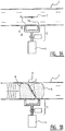
- the valve illustrated in figures 1A and 1B can for instance be a butterfly valve.
- the valve device comprises a housing 1 and a closing body 2 for closing a passage in housing 1 in mechanical manner.
- the closing body is movable between an open position ( figure 1A ) and a closing position ( figure 1B ). In the closing position, or close to the closing position, a gap 3 is present between housing 1 and closing body 2.
- the valve device further comprises a reservoir 4 for a flame-extinguishing substance, for instance a bottle of liquid CO 2 under pressure, and an injecting means 5 which is configured to inject the flame-extinguishing substance 6 into the passage for the purpose of preventing explosion propagation through gap 3.
- Injecting means 5 comprises an opening mechanism for opening a seal of reservoir 4 and two feed pipes leading to injection points 5a, 5b where the flame-extinguishing substance is injected into the passage in housing 1.
- the distance d between the opening mechanism and the injection points 5a, 5b is less than 20 cm, preferably less than 10 cm and still more preferably less than 5 cm.
- the valve device can further comprise an actuator (not shown) for moving closing body 2 from the open position to the closing position, and vice versa.
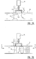
- FIGS 2A and 2B illustrate another variant according to the invention in which the closing body is an inflatable closing body 12 arranged in a housing 11 with a passage.
- the valve device further comprises a reservoir 14 for a flame-extinguishing substance which is also used in the illustrated embodiment to fill the closing body 12.
- two reservoirs are provided: a first reservoir with a substance for inflating the closing body and a second reservoir with a flame-extinguishing substance.
- An injecting means 15 is further provided for injecting the flame-extinguishing substance 16, on the one hand into closing body 12 and on the other into the passage in housing 11 on a side of the passage intended for connection to a space in which explosion hazard is present.
- Injecting means 15 comprises an opening mechanism for opening a seal of reservoir 14 and two feed pipes leading to an injection point 15a, where the flame-extinguishing substance is injected into the passage in housing 11, and an injection point 15b for inflating the closing body.
- Injection point 15a is located on the side where an explosion E can occur.
- the other side of closing body 12 is therefore a protected zone S.
- the distance d between the opening mechanism and injection point 15a is less than 20 cm, preferably less than 10 cm and still more preferably less than 5 cm.
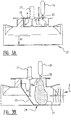
- FIGS 3A, 3B and 3C illustrate a third embodiment of a valve device according to the invention in the form of a non-return valve.
- the valve device comprises a housing 21 in which a passage extends.
- a closing body 22 for closing the passage.
- Closing body 22 is movable between an open position ( figure 3A ) and a closing position ( figure 3B ) .
- an actuator which here takes the form of a piston-cylinder assembly 27.
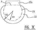
- Closing body 22 can be bent along an axis A and is provided with a fixing part 22a for fixing closing body 22 in housing 21 via one or more bolts 28.
- the passage has a substantially round form with a dimension R1 which is smaller than the corresponding dimension R2 of closing body 22.
- Designing the closing body 22 in such a manner ensures that the closing body deforms plastically during the movement of closing body 22 from the open position to the closing position.
- a peripheral part 29 can optionally take a weakened form, for instance by giving this part a wholly or partially thinner form, or by providing recesses therein.
- the peripheral part 29 of closing body 22 will be bent. Owing to this plastic deformation a part of the energy of closing body 22 is absorbed, in particular the kinetic energy, whereby the closing body is braked.
- closing body 22 can also be mounted hingedly in the housing, wherein fixing part 22a is then omitted.
- the passage can have any random form, wherein the design of the closing body is adapted to the design of the passage.
- the valve device comprises a reservoir 24 for storing a flame-extinguishing substance under pressure, typically CO 2 , and an opening mechanism 25 in the form of a valve to allow the flame-extinguishing substance through into the passage of housing 21.
- the flame-extinguishing substance is preferably injected in good time and for long enough to prevent or limit explosion propagation in reliable manner.
- the distance d between opening mechanism 25 and injection point 25a into the passage is preferably as small as possible.
- the distance d is preferably less than 10 cm, still more preferably less than 5 cm.
- the reservoir is preferably mounted for this purpose directly on housing 21.
- the injected flame-extinguishing substance 26 extends over the whole passage and thus prevents the possibility of an explosion E being propagated through possible gaps present between closing body 22 and the wall of the passage, see figure 3B .
Landscapes
- Health & Medical Sciences (AREA)
- Public Health (AREA)
- Business, Economics & Management (AREA)
- Emergency Management (AREA)
- Engineering & Computer Science (AREA)
- Mining & Mineral Resources (AREA)
- Life Sciences & Earth Sciences (AREA)
- General Life Sciences & Earth Sciences (AREA)
- Geochemistry & Mineralogy (AREA)
- Geology (AREA)
- Safety Valves (AREA)
- Lift Valve (AREA)
- Fire-Extinguishing By Fire Departments, And Fire-Extinguishing Equipment And Control Thereof (AREA)
- Feeding And Controlling Fuel (AREA)
Claims (15)
- Dispositif de soupape pour empêcher la propagation d'une explosion, comprenant :- un boîtier (1) et un corps de fermeture (2) pour fermer un passage dans le boîtier d'une manière mécanique, dans lequelle corps de fermeture est mobile entre une position ouverte et une position de fermeture ;- un actionneur (27) ;- un réservoir (4) pour une substance d'extinction de flamme (6) ;- un moyen d'injection (5) ;caractérisé en ce que l'actionneur est configuré pour déplacer le corps de fermeture de la position ouverte à la position de fermeture en moins de 100 ms ; que le moyen d'injection est configuré pour injecter la substance d'extinction de flamme dans le passage afin d'empêcher la propagation d'une explosion résultant d'une fermeture pas complètement hermétique par le corps de fermeture ; que le réservoir est un réservoir fermé dans lequel la substance d'extinction de flamme est stockée sous pression, que le moyen d'injection comprend un mécanisme d'ouverture (25) pour ouvrir le réservoir et que la distance entre le mécanisme d'ouverture et un point d'injection de la substance d'extinction de flamme dans le passage est inférieure à 20 cm.
- Dispositif de soupape selon la revendication 1, dans lequel l'actionneur est configuré pour déplacer le corps de fermeture de la position ouverte à la position de fermeture en moins de 30 ms.
- Dispositif de soupape selon la revendication 1 ou 2, comprenant en outre une commande pour faire fonctionner l'actionneur dans le but de déplacer le corps de fermeture vers la position de fermeture et pour faire fonctionner le moyen d'injection dans le but d'injecter la substance d'extinction de flamme ; et des moyens de détection pour détecter une explosion, lesquels moyens de détection sont reliés à la commande.
- Dispositif de soupape selon l'une quelconque des revendications précédentes, caractérisé en ce que le moyen d'injection est configuré pour injecter la substance d'extinction de flamme dans le passage dans une période de temps de moins de 15 ms, de préférence de moins de 10 ms, à la suite de la détection d'une explosion.
- Dispositif de soupape selon l'une quelconque des revendications précédentes, caractérisé en ce que la distance entre le mécanisme d'ouverture et un point d'injection de la substance d'extinction de flamme dans le passage est inférieure à 10 cm et de préférence inférieure à 5 cm.
- Dispositif de soupape selon l'une quelconque des revendications précédentes, caractérisé en ce que le réservoir est monté sur le boîtier.
- Dispositif de soupape selon l'une quelconque des revendications précédentes, caractérisé en ce que le moyen d'injection est configuré pour injecter la substance d'extinction de flamme de telle sorte que l'injection contribue au déplacement du corps de fermeture de la position ouverte à la position de fermeture.
- Dispositif de soupape selon l'une quelconque des revendications précédentes, caractérisé en ce que la substance d'extinction de flamme est l'une des substances suivantes ou une combinaison de celles-ci : CO2, poudre d'extinction, eau.
- Dispositif de soupape selon l'une quelconque des revendications précédentes, caractérisé en ce que le boîtier est pourvu d'un ou plusieurs canaux d'injection à travers lesquels la substance d'extinction de flamme peut être injectée ; et/ou en ce qu'au moins un canal d'injection pour la substance d'extinction de flamme est disposé sur le côté du passage destiné au raccordement à un espace dans lequel le risque d'explosion est présent ; et/ou en ce que le corps de fermeture est pourvu d'un ou plusieurs canaux d'injection à travers lesquels la substance d'extinction de flamme peut être injectée dans le passage.
- Dispositif de soupape selon l'une quelconque des revendications précédentes, caractérisé en ce qu'un espace est présent entre le corps de fermeture et le boîtier dans la position de fermeture, et que le moyen d'injection est configuré pour injecter la substance d'extinction de flamme dans le but d'empêcher la propagation d'une explosion à travers l'espace.
- Procédé pour empêcher la propagation d'une explosion dans un passage, comprenant la fermeture du passage d'une manière mécanique en déplaçant un corps de fermeture d'une position ouverte à une position de fermeture en moins de 100 ms, et l'injection d'une substance d'extinction de flamme depuis un réservoir dans le passage dans le but d'empêcher la propagation d'une explosion résultant d'une fermeture pas complètement hermétique par le corps de fermeture ; dans lequel l'injection est réalisée à l'aide d'un mécanisme d'ouverture pour ouvrir le réservoir, dans lequel la distance entre le mécanisme d'ouverture et un point d'injection de la substance d'extinction de flamme dans le passage est inférieure à 20 cm.
- Procédé selon la revendication 11, dans lequel le corps de fermeture est déplacé de la position ouverte à la position de fermeture en moins de 30 ms.
- Procédé selon la revendication 11 ou 12, comprenant en outre la détection d'une explosion, dans lequel la substance d'extinction de flamme est injectée dans le passage dans une période de temps de moins de 15 ms à la suite de la détection de l'explosion ; et/ou dans lequel la substance d'extinction de flamme est injectée de telle sorte que l'injection contribue au déplacement du corps de fermeture de la position ouverte à la position de fermeture ; et/ou dans lequel la substance d'extinction de flamme est injectée sur le côté du passage raccordé à un espace dans lequel le risque d'explosion est présent ; et/ou dans lequel un espace est présent entre le corps de fermeture et le boîtier dans la position de fermeture, et que la substance d'extinction de flamme est injectée dans le but d'empêcher la propagation d'une explosion à travers l'espace.
- Utilisation d'un dispositif de soupape selon l'une quelconque des revendications 1 à 10 pour empêcher la propagation d'une explosion.
- Système comprenant un dispositif de soupape selon l'une quelconque des revendications 1 à 10 et un contenant, habituellement un silo, dans lequel un risque d'explosion est présent, dans lequel le dispositif de soupape est disposé dans un conduit qui communique avec le contenant ; dans lequel la distance entre le dispositif de soupape et le contenant est comprise de préférence entre 0,5 m et 12 m.
Applications Claiming Priority (3)
| Application Number | Priority Date | Filing Date | Title |
|---|---|---|---|
| BE201200559A BE1020865A5 (nl) | 2012-08-27 | 2012-08-27 | Klepinrichting en werkwijze voor het verhinderen van explosiepropagatie. |
| BE2012/0742A BE1021418B1 (nl) | 2012-08-27 | 2012-10-29 | Klepinrichting en werkwijze voor het verhinderen van explosiepropagatie |
| PCT/BE2013/000042 WO2014032125A2 (fr) | 2012-08-27 | 2013-08-26 | Dispositif de soupape et procédé permettant d'empêcher la propagation d'une explosion |
Publications (2)
| Publication Number | Publication Date |
|---|---|
| EP2888015A2 EP2888015A2 (fr) | 2015-07-01 |
| EP2888015B1 true EP2888015B1 (fr) | 2020-03-11 |
Family
ID=49485458
Family Applications (2)
| Application Number | Title | Priority Date | Filing Date |
|---|---|---|---|
| EP13783222.6A Active EP2888015B1 (fr) | 2012-08-27 | 2013-08-26 | Dispositif de soupape et procédé permettant d'empêcher la propagation d'une explosion |
| EP13782643.4A Active EP2888014B1 (fr) | 2012-08-27 | 2013-08-26 | Élément de valve et procédé permettant d'empêcher une propagation d'explosion |
Family Applications After (1)
| Application Number | Title | Priority Date | Filing Date |
|---|---|---|---|
| EP13782643.4A Active EP2888014B1 (fr) | 2012-08-27 | 2013-08-26 | Élément de valve et procédé permettant d'empêcher une propagation d'explosion |
Country Status (4)
| Country | Link |
|---|---|
| US (1) | US9452303B2 (fr) |
| EP (2) | EP2888015B1 (fr) |
| AU (2) | AU2013308341B2 (fr) |
| WO (2) | WO2014032127A2 (fr) |
Families Citing this family (4)
| Publication number | Priority date | Publication date | Assignee | Title |
|---|---|---|---|---|
| CN104436478A (zh) * | 2014-12-04 | 2015-03-25 | 安徽理工大学 | 一种气固两相射流主动阻火抑爆方法 |
| US10758753B2 (en) * | 2015-10-30 | 2020-09-01 | Commonwealth Scientific And Industrial Research Organisation | Ducting system |
| WO2018213820A1 (fr) * | 2017-05-19 | 2018-11-22 | Bs&B Innovations Limited | Soupape à clapet anti-explosion |
| DE102018113770B4 (de) * | 2018-06-08 | 2026-02-12 | Leinemann Gmbh & Co. Kg | Verfahren zum Löschen einer Flammenfront und Löschvorrichtung |
Family Cites Families (9)
| Publication number | Priority date | Publication date | Assignee | Title |
|---|---|---|---|---|
| US2352378A (en) * | 1941-03-11 | 1944-06-27 | Reconstruction Finance Corp | Fire extinguishing method and apparatus |
| US3912015A (en) * | 1974-06-17 | 1975-10-14 | Armco Steel Corp | System for the safe handling of pulverized coal |
| SE455471B (sv) | 1985-11-29 | 1988-07-18 | Firefly Ab | Anordning for att forhindra risk for brand pa grund av brinnande eller glodande partiklar i en rorledning |
| US5402603A (en) * | 1992-01-03 | 1995-04-04 | Henley; Robert L. | Flapper plate detonation flame arrester |
| FR2697435B1 (fr) * | 1992-10-29 | 1994-12-16 | France Air | Ralentisseur thermique pour appareil de ventilation destiné à la protection contre l'incendie. |
| US5676712A (en) * | 1995-05-16 | 1997-10-14 | Atmi Ecosys Corporation | Flashback protection apparatus and method for suppressing deflagration in combustion-susceptible gas flows |
| GB2318975B (en) * | 1996-05-01 | 2000-03-08 | Nullifire Ltd | Fire resistant duct |
| DE19701678A1 (de) * | 1997-01-18 | 1998-07-23 | Stauber & Partner Beratende In | Brand- und Rauchschutzvorrichtung für eine Rohrleitung |
| US6112823A (en) * | 1999-11-09 | 2000-09-05 | O'leary; James | Waste fire suppression control device |
-
2013
- 2013-08-26 EP EP13783222.6A patent/EP2888015B1/fr active Active
- 2013-08-26 US US14/423,606 patent/US9452303B2/en active Active
- 2013-08-26 WO PCT/BE2013/000045 patent/WO2014032127A2/fr not_active Ceased
- 2013-08-26 AU AU2013308341A patent/AU2013308341B2/en active Active
- 2013-08-26 AU AU2013308339A patent/AU2013308339B2/en active Active
- 2013-08-26 EP EP13782643.4A patent/EP2888014B1/fr active Active
- 2013-08-26 WO PCT/BE2013/000042 patent/WO2014032125A2/fr not_active Ceased
Non-Patent Citations (1)
| Title |
|---|
| None * |
Also Published As
| Publication number | Publication date |
|---|---|
| WO2014032127A2 (fr) | 2014-03-06 |
| US9452303B2 (en) | 2016-09-27 |
| WO2014032125A2 (fr) | 2014-03-06 |
| EP2888014B1 (fr) | 2020-03-11 |
| US20150238787A1 (en) | 2015-08-27 |
| EP2888015A2 (fr) | 2015-07-01 |
| AU2013308339B2 (en) | 2017-04-13 |
| EP2888014A2 (fr) | 2015-07-01 |
| AU2013308341B2 (en) | 2017-03-02 |
| AU2013308339A1 (en) | 2015-03-12 |
| WO2014032125A3 (fr) | 2014-04-24 |
| WO2014032127A3 (fr) | 2014-04-24 |
| AU2013308341A1 (en) | 2015-03-12 |
Similar Documents
| Publication | Publication Date | Title |
|---|---|---|
| US9452303B2 (en) | Valve device and method for preventing explosion propagation | |
| JP2014522255A5 (fr) | ||
| US8381763B2 (en) | Gas filling and dispensing device, vessel with such device, and operational circuit | |
| CA2559950A1 (fr) | Ensemble de gavage et regulateur de debit avec fonctions sures de capacite de charge | |
| WO2018236223A2 (fr) | Dispositif d'étanchéité de soupape | |
| ES2500045T3 (es) | Racor de llenado, recipiente y procedimiento de llenado | |
| CA2971034C (fr) | Mecanisme de securite desactive de l'installation | |
| GB2511123B (en) | Butterfly valve | |
| KR102043164B1 (ko) | 화재진압 기동시스템 | |
| BE1020865A5 (nl) | Klepinrichting en werkwijze voor het verhinderen van explosiepropagatie. | |
| KR101412977B1 (ko) | 소화기용 밸브 | |
| KR20090001152U (ko) | 자동소화기용 실린더 밸브 | |
| RU2429187C1 (ru) | Муфта индикаторная поворотно-разрывная | |
| RU138048U1 (ru) | Предохранительный клапан | |
| ES2942149T3 (es) | Sistema y método para inyectar un agente extintor en el caso de peligro de explosión | |
| CN201065750Y (zh) | 一种油井油气磁控防盗阀门 | |
| EP2178712B1 (fr) | Système pour remplir un réservoir | |
| CN203627780U (zh) | 一种压力安全联锁装置 | |
| RU2308628C2 (ru) | Запорный клапан для топливного бака либо цистерны | |
| CN105370948A (zh) | 一种车用气瓶充装和使用的启、闭装置 | |
| CN104595502A (zh) | 具有高密封性能的截止阀 | |
| KR102048376B1 (ko) | 분사 기능을 가지는 컨베이어용 롤러 | |
| RU2220363C2 (ru) | Газовый баллон с предохранительным клапаном | |
| CN105593585A (zh) | 用于阀的锁定装置 | |
| NL2022748A (en) | Fire safety sprinkler head, fire prevention and/or extinguishing installation and method for protecting a fire prevention and/or extinguishing installation against corrosion |
Legal Events
| Date | Code | Title | Description |
|---|---|---|---|
| PUAI | Public reference made under article 153(3) epc to a published international application that has entered the european phase |
Free format text: ORIGINAL CODE: 0009012 |
|
| 17P | Request for examination filed |
Effective date: 20150313 |
|
| AK | Designated contracting states |
Kind code of ref document: A2 Designated state(s): AL AT BE BG CH CY CZ DE DK EE ES FI FR GB GR HR HU IE IS IT LI LT LU LV MC MK MT NL NO PL PT RO RS SE SI SK SM TR |
|
| AX | Request for extension of the european patent |
Extension state: BA ME |
|
| DAX | Request for extension of the european patent (deleted) | ||
| GRAP | Despatch of communication of intention to grant a patent |
Free format text: ORIGINAL CODE: EPIDOSNIGR1 |
|
| STAA | Information on the status of an ep patent application or granted ep patent |
Free format text: STATUS: GRANT OF PATENT IS INTENDED |
|
| INTG | Intention to grant announced |
Effective date: 20191031 |
|
| GRAS | Grant fee paid |
Free format text: ORIGINAL CODE: EPIDOSNIGR3 |
|
| GRAA | (expected) grant |
Free format text: ORIGINAL CODE: 0009210 |
|
| STAA | Information on the status of an ep patent application or granted ep patent |
Free format text: STATUS: THE PATENT HAS BEEN GRANTED |
|
| AK | Designated contracting states |
Kind code of ref document: B1 Designated state(s): AL AT BE BG CH CY CZ DE DK EE ES FI FR GB GR HR HU IE IS IT LI LT LU LV MC MK MT NL NO PL PT RO RS SE SI SK SM TR |
|
| REG | Reference to a national code |
Ref country code: GB Ref legal event code: FG4D |
|
| REG | Reference to a national code |
Ref country code: CH Ref legal event code: EP |
|
| REG | Reference to a national code |
Ref country code: AT Ref legal event code: REF Ref document number: 1242415 Country of ref document: AT Kind code of ref document: T Effective date: 20200315 |
|
| REG | Reference to a national code |
Ref country code: IE Ref legal event code: FG4D |
|
| REG | Reference to a national code |
Ref country code: DE Ref legal event code: R096 Ref document number: 602013066734 Country of ref document: DE |
|
| REG | Reference to a national code |
Ref country code: CH Ref legal event code: NV Representative=s name: ARNOLD AND SIEDSMA AG, CH |
|
| REG | Reference to a national code |
Ref country code: NL Ref legal event code: FP |
|
| PG25 | Lapsed in a contracting state [announced via postgrant information from national office to epo] |
Ref country code: RS Free format text: LAPSE BECAUSE OF FAILURE TO SUBMIT A TRANSLATION OF THE DESCRIPTION OR TO PAY THE FEE WITHIN THE PRESCRIBED TIME-LIMIT Effective date: 20200311 Ref country code: NO Free format text: LAPSE BECAUSE OF FAILURE TO SUBMIT A TRANSLATION OF THE DESCRIPTION OR TO PAY THE FEE WITHIN THE PRESCRIBED TIME-LIMIT Effective date: 20200611 Ref country code: FI Free format text: LAPSE BECAUSE OF FAILURE TO SUBMIT A TRANSLATION OF THE DESCRIPTION OR TO PAY THE FEE WITHIN THE PRESCRIBED TIME-LIMIT Effective date: 20200311 |
|
| PG25 | Lapsed in a contracting state [announced via postgrant information from national office to epo] |
Ref country code: SE Free format text: LAPSE BECAUSE OF FAILURE TO SUBMIT A TRANSLATION OF THE DESCRIPTION OR TO PAY THE FEE WITHIN THE PRESCRIBED TIME-LIMIT Effective date: 20200311 Ref country code: GR Free format text: LAPSE BECAUSE OF FAILURE TO SUBMIT A TRANSLATION OF THE DESCRIPTION OR TO PAY THE FEE WITHIN THE PRESCRIBED TIME-LIMIT Effective date: 20200612 Ref country code: LV Free format text: LAPSE BECAUSE OF FAILURE TO SUBMIT A TRANSLATION OF THE DESCRIPTION OR TO PAY THE FEE WITHIN THE PRESCRIBED TIME-LIMIT Effective date: 20200311 Ref country code: HR Free format text: LAPSE BECAUSE OF FAILURE TO SUBMIT A TRANSLATION OF THE DESCRIPTION OR TO PAY THE FEE WITHIN THE PRESCRIBED TIME-LIMIT Effective date: 20200311 Ref country code: BG Free format text: LAPSE BECAUSE OF FAILURE TO SUBMIT A TRANSLATION OF THE DESCRIPTION OR TO PAY THE FEE WITHIN THE PRESCRIBED TIME-LIMIT Effective date: 20200611 |
|
| REG | Reference to a national code |
Ref country code: LT Ref legal event code: MG4D |
|
| PG25 | Lapsed in a contracting state [announced via postgrant information from national office to epo] |
Ref country code: EE Free format text: LAPSE BECAUSE OF FAILURE TO SUBMIT A TRANSLATION OF THE DESCRIPTION OR TO PAY THE FEE WITHIN THE PRESCRIBED TIME-LIMIT Effective date: 20200311 Ref country code: SM Free format text: LAPSE BECAUSE OF FAILURE TO SUBMIT A TRANSLATION OF THE DESCRIPTION OR TO PAY THE FEE WITHIN THE PRESCRIBED TIME-LIMIT Effective date: 20200311 Ref country code: IS Free format text: LAPSE BECAUSE OF FAILURE TO SUBMIT A TRANSLATION OF THE DESCRIPTION OR TO PAY THE FEE WITHIN THE PRESCRIBED TIME-LIMIT Effective date: 20200711 Ref country code: PT Free format text: LAPSE BECAUSE OF FAILURE TO SUBMIT A TRANSLATION OF THE DESCRIPTION OR TO PAY THE FEE WITHIN THE PRESCRIBED TIME-LIMIT Effective date: 20200805 Ref country code: SK Free format text: LAPSE BECAUSE OF FAILURE TO SUBMIT A TRANSLATION OF THE DESCRIPTION OR TO PAY THE FEE WITHIN THE PRESCRIBED TIME-LIMIT Effective date: 20200311 Ref country code: CZ Free format text: LAPSE BECAUSE OF FAILURE TO SUBMIT A TRANSLATION OF THE DESCRIPTION OR TO PAY THE FEE WITHIN THE PRESCRIBED TIME-LIMIT Effective date: 20200311 Ref country code: RO Free format text: LAPSE BECAUSE OF FAILURE TO SUBMIT A TRANSLATION OF THE DESCRIPTION OR TO PAY THE FEE WITHIN THE PRESCRIBED TIME-LIMIT Effective date: 20200311 Ref country code: LT Free format text: LAPSE BECAUSE OF FAILURE TO SUBMIT A TRANSLATION OF THE DESCRIPTION OR TO PAY THE FEE WITHIN THE PRESCRIBED TIME-LIMIT Effective date: 20200311 |
|
| REG | Reference to a national code |
Ref country code: AT Ref legal event code: MK05 Ref document number: 1242415 Country of ref document: AT Kind code of ref document: T Effective date: 20200311 |
|
| REG | Reference to a national code |
Ref country code: DE Ref legal event code: R097 Ref document number: 602013066734 Country of ref document: DE |
|
| PLBE | No opposition filed within time limit |
Free format text: ORIGINAL CODE: 0009261 |
|
| STAA | Information on the status of an ep patent application or granted ep patent |
Free format text: STATUS: NO OPPOSITION FILED WITHIN TIME LIMIT |
|
| PG25 | Lapsed in a contracting state [announced via postgrant information from national office to epo] |
Ref country code: DK Free format text: LAPSE BECAUSE OF FAILURE TO SUBMIT A TRANSLATION OF THE DESCRIPTION OR TO PAY THE FEE WITHIN THE PRESCRIBED TIME-LIMIT Effective date: 20200311 Ref country code: AT Free format text: LAPSE BECAUSE OF FAILURE TO SUBMIT A TRANSLATION OF THE DESCRIPTION OR TO PAY THE FEE WITHIN THE PRESCRIBED TIME-LIMIT Effective date: 20200311 Ref country code: ES Free format text: LAPSE BECAUSE OF FAILURE TO SUBMIT A TRANSLATION OF THE DESCRIPTION OR TO PAY THE FEE WITHIN THE PRESCRIBED TIME-LIMIT Effective date: 20200311 Ref country code: IT Free format text: LAPSE BECAUSE OF FAILURE TO SUBMIT A TRANSLATION OF THE DESCRIPTION OR TO PAY THE FEE WITHIN THE PRESCRIBED TIME-LIMIT Effective date: 20200311 |
|
| 26N | No opposition filed |
Effective date: 20201214 |
|
| PG25 | Lapsed in a contracting state [announced via postgrant information from national office to epo] |
Ref country code: PL Free format text: LAPSE BECAUSE OF FAILURE TO SUBMIT A TRANSLATION OF THE DESCRIPTION OR TO PAY THE FEE WITHIN THE PRESCRIBED TIME-LIMIT Effective date: 20200311 Ref country code: SI Free format text: LAPSE BECAUSE OF FAILURE TO SUBMIT A TRANSLATION OF THE DESCRIPTION OR TO PAY THE FEE WITHIN THE PRESCRIBED TIME-LIMIT Effective date: 20200311 |
|
| PG25 | Lapsed in a contracting state [announced via postgrant information from national office to epo] |
Ref country code: MC Free format text: LAPSE BECAUSE OF FAILURE TO SUBMIT A TRANSLATION OF THE DESCRIPTION OR TO PAY THE FEE WITHIN THE PRESCRIBED TIME-LIMIT Effective date: 20200311 |
|
| PG25 | Lapsed in a contracting state [announced via postgrant information from national office to epo] |
Ref country code: LU Free format text: LAPSE BECAUSE OF NON-PAYMENT OF DUE FEES Effective date: 20200826 |
|
| PG25 | Lapsed in a contracting state [announced via postgrant information from national office to epo] |
Ref country code: IE Free format text: LAPSE BECAUSE OF NON-PAYMENT OF DUE FEES Effective date: 20200826 |
|
| PG25 | Lapsed in a contracting state [announced via postgrant information from national office to epo] |
Ref country code: TR Free format text: LAPSE BECAUSE OF FAILURE TO SUBMIT A TRANSLATION OF THE DESCRIPTION OR TO PAY THE FEE WITHIN THE PRESCRIBED TIME-LIMIT Effective date: 20200311 Ref country code: MT Free format text: LAPSE BECAUSE OF FAILURE TO SUBMIT A TRANSLATION OF THE DESCRIPTION OR TO PAY THE FEE WITHIN THE PRESCRIBED TIME-LIMIT Effective date: 20200311 Ref country code: CY Free format text: LAPSE BECAUSE OF FAILURE TO SUBMIT A TRANSLATION OF THE DESCRIPTION OR TO PAY THE FEE WITHIN THE PRESCRIBED TIME-LIMIT Effective date: 20200311 |
|
| PG25 | Lapsed in a contracting state [announced via postgrant information from national office to epo] |
Ref country code: MK Free format text: LAPSE BECAUSE OF FAILURE TO SUBMIT A TRANSLATION OF THE DESCRIPTION OR TO PAY THE FEE WITHIN THE PRESCRIBED TIME-LIMIT Effective date: 20200311 Ref country code: AL Free format text: LAPSE BECAUSE OF FAILURE TO SUBMIT A TRANSLATION OF THE DESCRIPTION OR TO PAY THE FEE WITHIN THE PRESCRIBED TIME-LIMIT Effective date: 20200311 |
|
| PGFP | Annual fee paid to national office [announced via postgrant information from national office to epo] |
Ref country code: NL Payment date: 20250826 Year of fee payment: 13 |
|
| PGFP | Annual fee paid to national office [announced via postgrant information from national office to epo] |
Ref country code: DE Payment date: 20250827 Year of fee payment: 13 |
|
| PGFP | Annual fee paid to national office [announced via postgrant information from national office to epo] |
Ref country code: BE Payment date: 20250827 Year of fee payment: 13 Ref country code: GB Payment date: 20250827 Year of fee payment: 13 |
|
| PGFP | Annual fee paid to national office [announced via postgrant information from national office to epo] |
Ref country code: FR Payment date: 20250825 Year of fee payment: 13 |
|
| PGFP | Annual fee paid to national office [announced via postgrant information from national office to epo] |
Ref country code: CH Payment date: 20250901 Year of fee payment: 13 |