EP2888444B1 - Système et procédé permettant de corriger la vitesse d'un train d'outils de fond de puits - Google Patents
Système et procédé permettant de corriger la vitesse d'un train d'outils de fond de puits Download PDFInfo
- Publication number
- EP2888444B1 EP2888444B1 EP12746160.6A EP12746160A EP2888444B1 EP 2888444 B1 EP2888444 B1 EP 2888444B1 EP 12746160 A EP12746160 A EP 12746160A EP 2888444 B1 EP2888444 B1 EP 2888444B1
- Authority
- EP
- European Patent Office
- Prior art keywords
- speed
- tool
- depth
- pow
- calculated
- Prior art date
- Legal status (The legal status is an assumption and is not a legal conclusion. Google has not performed a legal analysis and makes no representation as to the accuracy of the status listed.)
- Not-in-force
Links
- 238000000034 method Methods 0.000 title claims description 36
- 238000012937 correction Methods 0.000 claims description 60
- 230000005484 gravity Effects 0.000 claims description 28
- 238000004364 calculation method Methods 0.000 claims description 26
- 239000012530 fluid Substances 0.000 description 15
- 230000015572 biosynthetic process Effects 0.000 description 7
- 238000005755 formation reaction Methods 0.000 description 7
- 238000005259 measurement Methods 0.000 description 7
- 230000008859 change Effects 0.000 description 4
- 238000006243 chemical reaction Methods 0.000 description 4
- 230000003993 interaction Effects 0.000 description 4
- 238000005086 pumping Methods 0.000 description 4
- 230000000694 effects Effects 0.000 description 3
- 230000005251 gamma ray Effects 0.000 description 3
- 238000012544 monitoring process Methods 0.000 description 3
- 230000008569 process Effects 0.000 description 3
- 230000008878 coupling Effects 0.000 description 2
- 238000010168 coupling process Methods 0.000 description 2
- 238000005859 coupling reaction Methods 0.000 description 2
- 238000007435 diagnostic evaluation Methods 0.000 description 2
- 238000005553 drilling Methods 0.000 description 2
- 239000004215 Carbon black (E152) Substances 0.000 description 1
- 230000009471 action Effects 0.000 description 1
- 230000002411 adverse Effects 0.000 description 1
- 238000000429 assembly Methods 0.000 description 1
- 230000000712 assembly Effects 0.000 description 1
- 230000005540 biological transmission Effects 0.000 description 1
- 238000004891 communication Methods 0.000 description 1
- 238000010586 diagram Methods 0.000 description 1
- 238000005516 engineering process Methods 0.000 description 1
- 238000010304 firing Methods 0.000 description 1
- 229930195733 hydrocarbon Natural products 0.000 description 1
- 150000002430 hydrocarbons Chemical class 0.000 description 1
- 238000005461 lubrication Methods 0.000 description 1
- 239000000463 material Substances 0.000 description 1
- 238000012986 modification Methods 0.000 description 1
- 230000004048 modification Effects 0.000 description 1
- 230000002285 radioactive effect Effects 0.000 description 1
- 230000004044 response Effects 0.000 description 1
- 239000000126 substance Substances 0.000 description 1
- 238000004441 surface measurement Methods 0.000 description 1
- 230000008961 swelling Effects 0.000 description 1
- 238000011144 upstream manufacturing Methods 0.000 description 1
Images



Classifications
-
- E—FIXED CONSTRUCTIONS
- E21—EARTH OR ROCK DRILLING; MINING
- E21B—EARTH OR ROCK DRILLING; OBTAINING OIL, GAS, WATER, SOLUBLE OR MELTABLE MATERIALS OR A SLURRY OF MINERALS FROM WELLS
- E21B47/00—Survey of boreholes or wells
- E21B47/04—Measuring depth or liquid level
-
- E—FIXED CONSTRUCTIONS
- E21—EARTH OR ROCK DRILLING; MINING
- E21B—EARTH OR ROCK DRILLING; OBTAINING OIL, GAS, WATER, SOLUBLE OR MELTABLE MATERIALS OR A SLURRY OF MINERALS FROM WELLS
- E21B47/00—Survey of boreholes or wells
- E21B47/01—Devices for supporting measuring instruments on drill bits, pipes, rods or wirelines; Protecting measuring instruments in boreholes against heat, shock, pressure or the like
Definitions
- the present disclosure relates to systems and methods for conveying perforating and/or logging tools (hereinafter referred to as a "tool string”) in a wellbore where adverse conditions may be present to challenge downward movement of the tool string in the wellbore.
- a tool string perforating and/or logging tools
- Diagnostic evaluation well logs are generated by data obtained by diagnostic tools (referred to in the industry as logging tools) that are lowered into the wellbore and passed across geologic formations that may contain hydrocarbon substances. Examples of well logs and logging tools are known in the art. Examples of such diagnostic well logs include Neutron logs, Gamma Ray logs, Resistivity logs and Acoustic logs. Logging tools frequently are used for log data acquisition in a wellbore by logging in an upward (up hole) direction, from a bottom portion of the wellbore to an upper portion of the wellbore.
- wellbores can be highly deviated, or can include a substantially horizontal section. Such wellbores make downward movement of the logging tools in the wellbore difficult, as gravitational force becomes insufficient to convey the logging tools downhole.
- the present disclosure relates to a method and system for correcting the downhole speed at which perforating and/or logging tools (hereinafter referred to as a "tool string”) are moving in a wellbore.
- the disclosed systems, assemblies, and methods can reduce risk of damage to the tool string and increase speed and reliability of moving the tool string into and out of wellbores.
- certain wells can be drilled in a deviated manner or with a substantially horizontal section.
- the wells may be drilled through geologic formations that are subject to swelling or caving, or may have fluid pressures that make passage of the tool string unsuitable for common conveyance techniques.
- the present disclosure overcomes these difficulties and provides several technical advances.
- the present disclosure relates generally to a system and method for correcting the speed of tool strings that are being lowered into or pulled out of a wellbore.
- the tool strings may be connected to the lower end of an electric wireline or slickline cable that is spooled off a truck located at the surface.
- an electric wireline or slickline cable that is spooled off a truck located at the surface.
- the terms “cable” and “line” and “wireline” are used interchangeably and unless described with more specificity may include an electric wireline cable or a slickline cable.
- the tool string may be lowered into the wellbore via a drill pipe string, a coiled tubing string, and a conventional tubing string.
- the subject method and system are used in some implementations in a cased wellbore or in other implementations are applicable in a partially cased wellbore.
- the tool string is adapted for use in highly deviated wellbores wherein it is a known practice to pump fluid from the surface behind a tool string to assist the tool in moving down the deviated wellbore.
- the tool string of the present disclosure includes a device that measures the tension in the cable at the cable head and transmits that data as an analog signal to the surface via an electric wireline cable or other transmission means, and uses that data to control pumps and/or line speed.
- the tool string of the present disclosure may include a device that calculates the speed of the downhole tool string at the cable head and transmits that data as an analog signal.
- a device that calculates the speed of the downhole tool string at the cable head and transmits that data as an analog signal.
- Examples of such devices include an accelerometer and/or a casing collar locator.
- a casing collar locator may be used to correct the downhole speed calculations.
- a method of correcting a downhole speed of a tool string moving in a wellbore comprising: (a) inserting a tool string into a proximal upper end of the wellbore, said tool string comprising: a cable head connected at a first end to a cable; a casing collar locator; an accelerometer; at least one downhole tool selected from the group consisting of a logging tool and a perforating tool; (b) spooling out cable at the surface allowing the tool string to move into the wellbore; (c) obtaining data with an accelerometer and providing said data to a processor that calculates the downhole speed of the tool string based on the data from the accelerometer; (d) moving the tool string past at least two casing collars and sending data to the processor including the depth of each of the collars and time that the casing collar locator passes each of the casing collars; (e) calculating by the processor an average tool speed over the interval between collar
- the method can also include determining by the processor that the average calculated downhole tool speed is less than or greater than the measured line speed, determining a correction factor, and determining a corrected downhole tool speed.
- the method can include determining by the processor that the casing collar is recorded at a measured depth where expected, determining a correction factor, and determining a corrected downhole tool speed.
- the method can include determining by the processor that the casing collar at calculated depth is shallower/deeper than expected, determining a correction factor, and determining a corrected downhole tool speed.
- the correction factor can be calculated using measured casing collar depth, time, and calculated casing collar depth.
- a method of correcting a downhole speed of a tool string moving in a wellbore comprising: (a) inserting a tool string into a proximal upper end of the wellbore, said tool string comprising: a cable head connected at a first end to a cable; a casing collar locator; at least one downhole tool selected from the group consisting of a logging tool and a perforating tool; (b) spooling out cable at the surface allowing the tool string to move into the wellbore; (c) moving the tool string past at least two casing collars and sending data to a processor including the depth of each of the collars and time that the casing collar locator passes each of the casing collars; (d) calculating the average tool speed over the interval between collars using the depth of each of the collars and time that the casing collar locator passes each of the casing collars; (e) determining that the average calculated downhole tool speed is less than or
- the method can include determining that a casing collar is recorded at a measured depth where expected, determining a correction factor, and determining a corrected downhole tool speed.
- the method can include determining that a casing collar at calculated depth is shallower/deeper than expected, determining a correction factor, and determining a corrected downhole tool speed.
- the correction factor can be calculated using measured casing collar depth, time, and calculated casing collar depth.
- a well logging system 100 said system including: a tool string 200 comprising: a cable head 211 connected at a first end to a cable 111; a casing collar locator 220; an accelerometer 221; at least one downhole tool selected from the group consisting of a logging tool 231; 241; 243; 251 and a perforating tool 250; and a processor adapted to: receive data from the accelerometer 221 and calculate a downhole tool speed; receive data from the casing collar locator 220 including the depth of each of the collars 116 and time when the casing collar locator 230 passes at least two different casing collars 116; calculate the average downhole tool speed over the interval between collars 116; compare the downhole tool speed as calculated by the processor using the data from the accelerometer (221) to the average downhole tool speed calculated by the processor based on the time and casing collar location; determine that the average calculated downhole tool speed is less than or greater than downhole speed calculated
- the system can also include the processor being adapted for determining that the casing collar is recorded at a measured depth where expected, determining a correction factor, and determining a corrected downhole tool speed.
- the system can also include the processor being adapted for determining that the casing collar at calculated depth is shallower/deeper than expected, determining a correction factor, and determining a corrected downhole tool speed.
- the correction factor can be calculated using measured casing collar depth, time, and calculated casing collar depth.
- a well logging system 100 said system including: a tool string 200 comprising: a cable head 211 connected at a first end to a cable 111; a casing collar locator 220; at least one downhole tool selected form the group consisting of a logging tool 231; 241; 243; 251 and a perforating tool 250; and a processor adapted to: receive data from the casing collar locator 220 including the depth of each of the collars 116 and time when the casing collar locator 220 passes at least two different casing collars 116; and calculate the average downhole tool speed over the interval between collars 116; determine that the average calculated downhole tool speed is less than or greater than a measured line speed at the surface; determine a correction factor; and determine a corrected downhole tool speed.
- a tool string 200 comprising: a cable head 211 connected at a first end to a cable 111; a casing collar locator 220; at least one downhole tool selected form the group consisting of a logging tool 2
- the system can also include the processor being adapted for determining that the casing collar is recorded at a measured depth where expected, determining a correction factor, and determining a corrected downhole tool speed.
- the system can also include the processor being adapted for determining that the casing collar at calculated depth is shallower/deeper than expected, determining a correction factor, and determining a corrected downhole tool speed.
- the correction factor can be calculated using measured casing collar depth, time, and calculated casing collar depth.
- any use of any form of the terms “connect,” “engage,” “couple,” “attach,” or any other term describing an interaction between elements is not meant to limit the interaction to direct interaction between the elements and may also include indirect interaction between the elements described.
- Reference to up or down will be made for purposes of description with “up,” “upper,” “upwardly” or “upstream” meaning toward the surface of the well and with “down,” “lower,” “downwardly” or “downstream” meaning toward the terminal end of the well, regardless of the wellbore orientation.
- the pump rate of a pump unit (or units), the line speed for a logging/perforating (L/P) unit, and the line tension for the L/P unit may be automatically monitored and controlled to enable efficient pump down operations.
- pump down operations may be based on a predetermined line speed, a predetermined line tension and/or a predetermined pump rate. However, if any of these parameters change during pump down operations, the other parameters will be adjusted automatically.
- the techniques disclosed herein improve safety of pump down operations by eliminating the possibility of pumping the tools off the end of the wireline cable or other catastrophes.
- the line speed will be automatically reduced to maintain the desired line tension and the pump rate will be reduced in accordance with the amount of change in the line speed. Thereafter, if the monitored line tension drops below the predetermined threshold, the line speed will be automatically increased (up to a desired line speed) and the pump rate will be increased in accordance with the line speed.
- changes in the monitored pump rate during pump down operations may result in automated changes to the line tension and/or line speed of the L/P unit.
- FIG. 1 illustrates an example operation of a tool string 200.
- the system 100 includes surface equipment above the ground surface 105 and a wellbore 150 and its related equipment and instruments below the ground surface 105.
- surface equipment provides power, material, and structural support for the operation of the pump down tool string 200.
- the surface equipment includes a drilling rig 102 and associated equipment, and a data logging and control truck 115.
- the rig 102 may include equipment such as a rig pump 122 disposed proximal to the rig 102.
- the rig 102 can include equipment used when a well is being logged or later perforated such as a tool lubrication assembly 104 and a pack off pump 120.
- a blowout preventer 103 will be attached to a casing head 106 that is attached to an upper end of a well casing 112.
- the rig pump 122 provides pressurized drilling fluid to the rig and some of its associated equipment.
- a wireline and control truck 115 monitors the data logging operation and receives and stores logging data from the logging tools and/or controls and directs perforation operations.
- Below the rig 102 is the wellbore 150 extending from the surface 105 into the earth 110 and passing through a plurality of subterranean geologic formations 107.
- the wellbore 150 penetrates through the formations 107 and in some implementations forms a deviated path, which may include a substantially horizontal section as illustrated in FIG. 1 .
- the wellbore 150 may be reinforced with one or more casing strings 112 and 114.
- the tool string 200 may be attached with a cable/wireline 111 via a cable head 211.
- the conveying process is conducted by pumping a fluid from the rig pump 122 into the upper proximal end of the casing string 112 (or 114) above the tool string 200 to assist, via fluid pressure on the tool string 200, movement of the tool string 200 down the wellbore 150.
- the pump pressure of the fluid above the tool string 200 is monitored, for example, by the truck 115, because the fluid pressure can change during the conveying process and exhibit patterns indicating events such as sticking of the tool string in the wellbore.
- the cable 111 is spooled out at the surface by the truck 115.
- the tool string will have sufficient weight that gravity will convey the tool string down the wellbore without the assistance of pump fluid pressure.
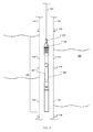
- FIGS. 2A to 2E are side views of an example logging tool string 200 applicable to the operations illustrated in FIG. 1 .
- the tool string 200 may include various data logging instruments used for data acquisition; for example, a casing collar locator 220, a telemetry gamma ray tool 231, a density neutron logging tool 241, a borehole sonic array logging tool 243, a compensated true resistivity tool array 251, among others as are well known in the art.
- the tool string is securely connected with the cable 111 by cable head tool 211.
- the rate at which the cable 111 is spooled out maintains movement control of the tool string 200 at a desired speed.
- an accelerometer 221 may be included in the tool string 200 at various locations.
- One acceptable location is illustrated in Fig. 2A and Fig. 3 .
- the tool string 200 further includes the telemetry gamma ray tool 231.
- the telemetry gamma ray tool 231 can record naturally occurring gamma rays in the formations adjacent to the wellbore. This nuclear measurement can indicate the radioactive content of the formations.
- the tool string 200 further includes the density neutron logging tool 241 and the borehole sonic array logging tool 243.
- the tool string 200 further includes the compensated true resistivity tool array 251.
- the tool string 200 may include other data logging instruments besides those discussed in FIGS. 2A through 2E , or may include a subset of the presented instruments.
- the tool string 200 may include the casing collar locator 221, a firing head and perforating gun 250, as are well known in the art.
- the tool string 200 includes a load cell and/or triaxial accelerometer device.
- Casing collars 116 are couplings that connect two joints of pipe together.
- the coupling adds mass to the casing string 114 at the connections and the change in mass can be measured.
- the term "measured depth” 412 is used to describe the depth of the casing collar determined using surface measurement of the amount of cable spooled out into the wellbore with or without line tension correction.
- the term “calculated depth” 413 is used to describe the depth of the casing collar determined using depth information calculated from accelerometers, line tension, and/or other sensors, and may include measured depth in the calculation.
- the term “expected depth” 416 is used to describe the depth of the casing collar determined based on correlation logs or other references, and is considered to be the true depth or actual known depth.
- a casing collar at a known depth will be recorded and the current depth will be adjusted or the delta will be noted 402.
- the line will be spooled into the well, the casing collar locator data 404, accelerometer data 406, as well as the downhole line tension data 408 will be transmitted uphole to a surface processor that is part of the system.
- Downhole tension data 408 is used in speed correction algorithms that use line tension 410.
- the measured depth of the collar 412 will be noted as well as the time.
- the average tool speed over the interval between collars will be calculated and compared to the average line speed measured at the surface 414 and the average calculated downhole tool speed.
- the recorded depth 413 of the casing collar will be compared 418 to the expected actual depth 416.
- the expected actual depth 416 of the casing collar is based on previously recorded measurements used to determine the actual depth of the casing collar. This could be a Gamma Ray/CCL log or some other method of correlating the casing collar depth to the reference depth for the well.
- the aforementioned measurements and calculations can be used to determine a course of action across several possible scenarios.
- the calculated downhole tool speed is greater than measured line speed 420
- the casing collar is recorded at a measured depth 412 shallower than expected 418
- the casing collar at a calculated depth 413 is found where expected 422.
- the reaction is to do nothing 426, since the downhole calculation is determined to be correct.
- the calculated downhole tool speed is greater than measured line speed 420, the casing collar is recorded at a measured depth shallower than expected 418, and the casing collar at a calculated depth 413 is found where expected 422. In such examples, the reaction is to do nothing 426, since the downhole calculation is determined to be correct.
- the calculated downhole line speed is less than measured line speed 420, the casing collar is recorded at a measured depth deeper than expected 418, and the casing collar at calculated depth is found where expected 422. In such examples, the reaction is to do nothing 426, since the downhole calculation is determined to be correct.
- the average calculated downhole line speed is less than or greater than measured line speed 420
- the casing collar is recorded at a measured depth 412 where expected
- the casing collar at calculated depth is shallower/deeper than expected 422.
- the reaction is to do nothing 426, since the downhole calculation is determined to be correct.
- coefficients are recalculated 424 to calculate a new correction factor.
- the correction factor is calculated using measured casing collar depth 412, time, and calculated casing collar depth 413. Examples of equations that can be used to calculate the correction factor are given below:
- logging and/or perforating operations as described above and illustrated in FIGS. 1-4 may include the pump down operations with automated monitoring and control of various operational parameters.
- the pump rate of a pump unit (or units), the line speed for a logging/perforating (L/P) unit, and the line tension for the L/P unit may be automatically monitored and controlled to enable efficient pump down operations.
- the automatic monitoring and control of parameters such as the propelling force and rate for advancing the tool string into the borehole, the line speed for a wireline unit, and the line tension for the wireline unit is useful for any wireline tool in which the tool string is conveyed into the borehole (cased or uncased) and where it is desired to coordinate control of both the pumping unit and the feed of the tool on the wireline.
- Such principles may be applied to any wireline logging tool, and perforating tool string.
- a pumping unit is typical for use in pump down operations, other driving units are known which may be used for advancing wireline tools, such as powered tractors, and it is equally important that the driving force be balanced with wireline speed and wireline tension for such tools also.
- the method 400 may include fewer steps than those illustrated or more steps than those illustrated.
- the illustrated steps of the method 400 may be performed in the respective orders illustrated or in different orders than that illustrated.
- the method 400 may be performed simultaneously (e.g., substantially or otherwise).
- Other variations in the order of steps are also possible. Accordingly, other implementations are within the scope of the following claims.
Landscapes
- Geology (AREA)
- Physics & Mathematics (AREA)
- Life Sciences & Earth Sciences (AREA)
- Engineering & Computer Science (AREA)
- Mining & Mineral Resources (AREA)
- Environmental & Geological Engineering (AREA)
- Fluid Mechanics (AREA)
- General Life Sciences & Earth Sciences (AREA)
- Geophysics (AREA)
- Geochemistry & Mineralogy (AREA)
- Geophysics And Detection Of Objects (AREA)
- Earth Drilling (AREA)
- Excavating Of Shafts Or Tunnels (AREA)
- Length Measuring Devices With Unspecified Measuring Means (AREA)
Claims (16)
- Procédé de correction d'une vitesse de descente en fond de trou d'un train d'outils se déplaçant dans un trou de forage, ledit procédé comprenant les étapes consistant à :(a) insérer un train d'outils (200) dans une extrémité supérieure proximale du trou de forage (150), ledit train d'outils comprenant :une tête de câble (211) connectée à une première extrémité d'un câble (111) ;un localisateur de manchon (220) ;un accéléromètre (221) ;au moins un outil de descente en fond de trou sélectionné dans le groupe consistant en un outil de diagraphie (231 ; 241 ; 243 ; 251) et un outil de perforation (250) ;(b) dévider le câble à la surface en permettant au train d'outils de se déplacer dans le trou de forage ;(c) obtenir des données avec un accéléromètre et fournir lesdites données à un processeur qui calcule la vitesse de descente en fond de trou du train d'outils sur la base des données de l'accéléromètre ;(d) faire passer le train d'outils devant au moins deux manchons (116) et envoyer les données au processeur en incluant la profondeur de chacun des manchons et l'instant où le localisateur de manchon passe chacun des manchons ;(e) faire calculer par le processeur une vitesse d'outil moyenne sur l'intervalle entre manchons ; et(f) comparer la vitesse de descente en fond de trou du train d'outils telle que calculée par le processeur en utilisant les données de l'accéléromètre à la vitesse moyenne de l'outil calculée par le processeur sur la base du temps et des manchons.
- Procédé selon la revendication 1, comprenant en outre la détermination par le processeur :de ce que la vitesse moyenne de l'outil de descente en fond de trou calculée est inférieure à ou supérieure à la vitesse du train d'outils telle que calculée par le processeur en utilisant les données de l'accéléromètre, en déterminant un facteur de correction et en déterminant une vitesse d'outil de descente en fond de trou corrigée ; oude ce que le manchon est enregistré à une profondeur mesurée là où cela est attendu, en déterminant un facteur de correction et en déterminant une vitesse corrigée d'outil de descente en fond de trou ; oude ce que le manchon à la profondeur calculée est plus à la surface/plus en profondeur que ce qui est attendu, en déterminant un facteur de correction et en déterminant une vitesse corrigée d'outil de descente en fond de trou.
- Procédé selon la revendication 2, dans lequel le facteur de correction est calculé en utilisant une profondeur de manchon mesurée, un temps et une profondeur de manchon calculée.
- Procédé selon la revendication 2, dans lequel le facteur de correction est déterminé en partie en utilisant le calcul d'un coefficient de gravité donné par l'équation : gravité = pow(pow(AccX,2) + pow(AccY,2) + pow(AccZ,2), 0,5) et, facultativement, dans lequel le facteur de correction est déterminé en partie en utilisant un calcul d'une vitesse d'outil de descente en fond de trou donnée par l'équation : vitesse = 0,5 x pow(gravité,2.0)*pow(IntTime,2.0).
- Procédé de correction d'une vitesse de descente en fond de trou d'un train d'outils se déplaçant dans un trou de forage, ledit procédé comprenant les étapes consistant à :(a) insérer un train d'outils (200) dans une extrémité supérieure proximale du trou de forage (150), ledit train d'outils comprenant :une tête de câble (211) connectée à une première extrémité à un câble (111) ;un localisateur de manchon (220) ;au moins un outil de descente en fond de trou sélectionné parmi le groupe consistant en un outil de diagraphie (231, 241, 243, 251) et un outil de perforation (250) ;(b) dévider le câble à la surface en permettant au train d'outils de se déplacer dans le trou de forage ;(c) faire passer le train d'outils devant au moins deux manchons (116) et envoyer les données à un processeur en incluant la profondeur de chacun des manchons et l'instant auquel le localisateur de manchon passe devant chacun des manchons ;(d) calculer la vitesse moyenne d'outil sur l'intervalle entre manchons en utilisant la profondeur de chacun des manchons et l'instant auquel le localisateur de manchon passe chacun des manchons ;(e) déterminer le fait que la vitesse moyenne calculée de l'outil de descente en fond de trou est inférieure à ou supérieure à une vitesse de train mesurée à la surface ;(f) déterminer une vitesse corrigée d'outil de descente en fond de trou et(g) déterminer une vitesse corrigée d'outil de descente en fond de trou.
- Procédé selon la revendication 5, comprenant en outre la détermination que :un manchon (116) est enregistré à une profondeur mesurée là où cela est attendu ; ouun manchon (116) à une profondeur calculée est plus en surface/plus en profondeur que ce qui est attendu.
- Procédé selon les revendications 5 ou 6, dans lequel le facteur de correction est calculé en utilisant une profondeur de manchon mesurée, un temps et une profondeur de manchon calculée.
- Procédé selon l'une quelconque des revendications 5 ou 6, dans lequel le facteur de correction est déterminé en partie en utilisant un calcul d'un coefficient de gravité donné par l'équation : gravité = pow(pow(AccX,2) + pow(AccY,2) + pow(AccZ,2), 0.5) et, facultativement, dans lequel le facteur de correction est déterminé en partie en utilisant un calcul de vitesse d'outil de descente en fond de trou donnée par l'équation : vitesse = 0,5 * pow(gravité, 2.0) * pow(IntTime, 2.0).
- Système de diagraphie de puits (100), ledit système incluant :un train d'outils (200) comprenant :une tête de câble (211) connectée à une première extrémité à un câble (111) ;un localisateur de manchon (220) ;un accéléromètre (221) ;au moins un outil de descente en fond de trou sélectionné dans le groupe consistant en un outil de diagraphie (231, 241, 243, 251) et un outil de perforation (250) ; etun processeur adapté pour :recevoir des données de l'accéléromètre (221) et calculer une vitesse d'outil de descente en fond de trou ;recevoir des données du localisateur de manchon (220) incluant la profondeur de chacun des manchons (116) et l'instant où le localisateur (230) de manchon passe au moins deux manchons différents (116) ;calculer la vitesse moyenne d'outil de descente en fond de trou sur l'intervalle entre manchons (116) ;comparer la vitesse d'outil de descente en fond de trou telle que calculée par le processeur en utilisant les données de l'accéléromètre (221) à la vitesse moyenne d'outil de descente en fond de trou calculée par le processeur sur la base de l'instant et de la localisation du manchon ;déterminer le fait que la vitesse moyenne calculée de l'outil de descente en fond de trou est inférieure à ou supérieure à la vitesse de descente en fond de trou calculée par le processeur en utilisant les données de l'accéléromètre ;déterminer un facteur de correction ; etdéterminer une vitesse corrigée d'outil de descente en fond de trou.
- Système selon la revendication 9, dans lequel le processeur est en outre adapté pour déterminer :que le manchon est enregistré à une profondeur mesurée là où cela est attendu ouque le manchon à une profondeur calculée se trouve plus en surface/plus en profondeur que ce qui est attendu.
- Système selon la revendication 9 ou 10, dans lequel le facteur de correction est calculé à l'aide de la profondeur du manchon mesuré, un temps et la profondeur du manchon calculée.
- Système selon l'une des revendications 9 ou 10, dans lequel le facteur de correction est déterminé en partie en utilisant le calcul d'un coefficient de gravité donné par l'équation : gravité = pow(pow(AccX,2) + pow(AccY, 2) + pow(AccZ, 2), 0,5) et, facultativement, dans lequel le facteur de correction est déterminé en partie en utilisant un calcul d'une vitesse d'outil de descente en fond de trou donnée par l'équation : vitesse = 0,5 * pow(gravité, 2.0) * pow(intTime, 2.0).
- Système de diagraphie de puits (100), ledit système incluant :un train d'outils (200) comprenant :une tête de câble (211) connectée à une première extrémité à un câble (111) ;un localisateur de manchon (220) ;au moins un outil de descente en fond de trou sélectionné dans le groupe composé d'un outil de diagraphie (231, 241, 243, 251) et d'un outil de perforation (250) ; etun processeur adapté pour :recevoir des données du localisateur de manchon (220) incluant la profondeur de chacun des manchons (116) et l'instant où le localisateur de manchon (220) passe au moins deux manchons différents (116) etcalculer la vitesse moyenne d'outil de descente en fond de trou sur l'intervalle entre manchons (116) ;déterminer le fait que la vitesse moyenne d'outil de descente en fond de trou calculée est inférieure à ou supérieure à une vitesse de ligne mesurée à la surface ;déterminer un facteur de correction etdéterminer une vitesse corrigée d'outil de descente en fond de trou.
- Système selon la revendication 13, dans lequel le processeur est en outre adapté pour déterminer :que le manchon (116) est enregistré à une profondeur mesurée là où cela est attendu ouque le manchon (116) à une profondeur calculée est plus en surface/en profondeur que ce qui est attendu.
- Système selon les revendications 13 ou 14, dans lequel le facteur de correction est calculé en utilisant une profondeur de manchon mesurée, un instant et une profondeur de manchon calculée.
- Système selon la revendication 13 ou 14, dans lequel le facteur de correction est déterminé en partie en utilisant le calcul d'un coefficient de gravité donné par l'équation : gravité = pow(pow(AccX,2) + pow(AccY,2) + pow(AccZ,2), 0,5) et, facultativement, dans lequel le facteur de correction est déterminé en partie en utilisant le calcul d'une vitesse d'outil de descente en fond de trou donnée par l'équation : vitesse = 0,5 * pow (gravité, 2,0) * pow(intTime, 2,0).
Applications Claiming Priority (1)
| Application Number | Priority Date | Filing Date | Title |
|---|---|---|---|
| PCT/US2012/046867 WO2014014441A1 (fr) | 2012-07-16 | 2012-07-16 | Système et procédé permettant de corriger la vitesse d'un train d'outils de fond de puits |
Publications (2)
| Publication Number | Publication Date |
|---|---|
| EP2888444A1 EP2888444A1 (fr) | 2015-07-01 |
| EP2888444B1 true EP2888444B1 (fr) | 2016-11-16 |
Family
ID=46650870
Family Applications (1)
| Application Number | Title | Priority Date | Filing Date |
|---|---|---|---|
| EP12746160.6A Not-in-force EP2888444B1 (fr) | 2012-07-16 | 2012-07-16 | Système et procédé permettant de corriger la vitesse d'un train d'outils de fond de puits |
Country Status (7)
| Country | Link |
|---|---|
| US (1) | US8875785B2 (fr) |
| EP (1) | EP2888444B1 (fr) |
| AU (1) | AU2012385502B2 (fr) |
| BR (1) | BR112015000854A2 (fr) |
| CA (1) | CA2879415A1 (fr) |
| MX (1) | MX351730B (fr) |
| WO (1) | WO2014014441A1 (fr) |
Families Citing this family (10)
| Publication number | Priority date | Publication date | Assignee | Title |
|---|---|---|---|---|
| US9410419B2 (en) * | 2013-09-26 | 2016-08-09 | Halliburton Energy Services, Inc. | Device for measuring and transmitting downhole tension |
| WO2017123249A1 (fr) * | 2016-01-15 | 2017-07-20 | Halliburton Energy Services, Inc. | Appareil, procédé et système pour l'ajustement du débit de fluide annulaire autour d'un train de tiges d'outil |
| CN109653730B (zh) * | 2018-12-12 | 2021-12-14 | 中法渤海地质服务有限公司 | 一种用于钻杆地层测试作业井下射孔井段深度校准方法 |
| WO2020176352A1 (fr) * | 2019-02-25 | 2020-09-03 | Impact Selector International, Llc | Pompage automatisé |
| US11118425B2 (en) | 2019-08-19 | 2021-09-14 | Halliburton Energy Services, Inc. | Pumpdown regulator |
| US11125076B1 (en) * | 2020-07-21 | 2021-09-21 | Saudi Arabian Oil Company | Accelerometer based casing collar locator |
| WO2022126237A1 (fr) * | 2020-12-15 | 2022-06-23 | Intelligent Wellhead Systems Inc. | Système et procédé de commande d'opérations dans un puits |
| US12523138B2 (en) * | 2022-12-29 | 2026-01-13 | Halliburton Energy Services, Inc. | Autonomous start of pump-down operation |
| WO2025019411A1 (fr) * | 2023-07-14 | 2025-01-23 | Schlumberger Technology Corporation | Technique de positionnement d'outil |
| US12486762B2 (en) | 2024-01-11 | 2025-12-02 | Saudi Arabian Oil Company | Systems and methods for untethered wellbore investigation using modular autonomous device |
Family Cites Families (27)
| Publication number | Priority date | Publication date | Assignee | Title |
|---|---|---|---|---|
| US4252190A (en) | 1979-02-22 | 1981-02-24 | Standard Oil Company (Indiana) | Wireline stabilization method and apparatus |
| US4597440A (en) | 1985-04-04 | 1986-07-01 | Schlumberger Technology Corporation | Method and apparatus for displacing logging tools in deviated wells |
| US4662209A (en) * | 1986-02-07 | 1987-05-05 | Robert L. Brown | Course length measurement |
| FR2703727B1 (fr) | 1993-04-09 | 1995-06-30 | Schlumberger Services Petrol | Procédé et dispositif pour déterminer une correction de profondeur pour un outil de diagraphie dans un puits de pétrole. |
| GB2327501B (en) | 1997-07-22 | 2002-03-13 | Baroid Technology Inc | Improvements in or relating to aided inertial navigation systems |
| US6148263A (en) * | 1998-10-27 | 2000-11-14 | Schlumberger Technology Corporation | Activation of well tools |
| US6394184B2 (en) * | 2000-02-15 | 2002-05-28 | Exxonmobil Upstream Research Company | Method and apparatus for stimulation of multiple formation intervals |
| US6704655B2 (en) | 2000-10-12 | 2004-03-09 | Schlumberger Technology Corporation | Method and apparatus for correcting the depth index for well-log data |
| US6662645B2 (en) | 2001-02-08 | 2003-12-16 | Baker Hughes Incorporated | Apparatus and method for measuring forces on well logging instruments |
| US6618675B2 (en) | 2001-02-27 | 2003-09-09 | Halliburton Energy Services, Inc. | Speed correction using cable tension |
| US6896056B2 (en) | 2001-06-01 | 2005-05-24 | Baker Hughes Incorporated | System and methods for detecting casing collars |
| US7066284B2 (en) | 2001-11-14 | 2006-06-27 | Halliburton Energy Services, Inc. | Method and apparatus for a monodiameter wellbore, monodiameter casing, monobore, and/or monowell |
| US7696901B2 (en) | 2002-03-22 | 2010-04-13 | Schlumberger Technology Corporation | Methods and apparatus for photonic power conversion downhole |
| US6957580B2 (en) | 2004-01-26 | 2005-10-25 | Gyrodata, Incorporated | System and method for measurements of depth and velocity of instrumentation within a wellbore |
| US20050241835A1 (en) * | 2004-05-03 | 2005-11-03 | Halliburton Energy Services, Inc. | Self-activating downhole tool |
| US7142985B2 (en) | 2004-08-26 | 2006-11-28 | Baker Hughes Incorporated | Method and apparatus for improving wireline depth measurements |
| US7475486B1 (en) | 2007-08-21 | 2009-01-13 | Schlumberger Technology Corporation | Creep determination technique |
| US20090107725A1 (en) | 2007-10-30 | 2009-04-30 | Christy Thomas M | System and method for logging soil properties in a borehole |
| US7870900B2 (en) | 2007-11-16 | 2011-01-18 | Lufkin Industries, Inc. | System and method for controlling a progressing cavity well pump |
| US8037934B2 (en) | 2008-01-04 | 2011-10-18 | Intelligent Tools Ip, Llc | Downhole tool delivery system |
| US8061443B2 (en) | 2008-04-24 | 2011-11-22 | Schlumberger Technology Corporation | Downhole sample rate system |
| US7886847B2 (en) | 2008-05-23 | 2011-02-15 | Tesco Corporation | Monitoring flow rates while retrieving bottom hole assembly during casing while drilling operations |
| US8136591B2 (en) | 2009-06-01 | 2012-03-20 | Schlumberger Technology Corporation | Method and system for using wireline configurable wellbore instruments with a wired pipe string |
| WO2011149597A1 (fr) * | 2010-05-26 | 2011-12-01 | Exxonmobil Upstream Research Company | Ensemble et procédé pour stimulation de fracture multizone d'un réservoir utilisant des unités tubulaires autonomes |
| GB2497439B (en) | 2010-08-10 | 2017-06-14 | Halliburton Energy Services Inc | Automated controls for pump down operations |
| MY166617A (en) * | 2010-12-17 | 2018-07-17 | Exxonmobil Upstream Res Co | Method for automatic control and positioning of autonomous downhole tools |
| US9903192B2 (en) * | 2011-05-23 | 2018-02-27 | Exxonmobil Upstream Research Company | Safety system for autonomous downhole tool |
-
2012
- 2012-07-16 EP EP12746160.6A patent/EP2888444B1/fr not_active Not-in-force
- 2012-07-16 WO PCT/US2012/046867 patent/WO2014014441A1/fr not_active Ceased
- 2012-07-16 US US14/236,044 patent/US8875785B2/en not_active Expired - Fee Related
- 2012-07-16 CA CA2879415A patent/CA2879415A1/fr not_active Abandoned
- 2012-07-16 AU AU2012385502A patent/AU2012385502B2/en not_active Ceased
- 2012-07-16 BR BR112015000854A patent/BR112015000854A2/pt not_active Application Discontinuation
- 2012-07-16 MX MX2014015874A patent/MX351730B/es active IP Right Grant
Also Published As
| Publication number | Publication date |
|---|---|
| CA2879415A1 (fr) | 2014-01-23 |
| MX2014015874A (es) | 2015-08-14 |
| BR112015000854A2 (pt) | 2017-06-27 |
| WO2014014441A1 (fr) | 2014-01-23 |
| AU2012385502A1 (en) | 2015-01-22 |
| US8875785B2 (en) | 2014-11-04 |
| US20140202691A1 (en) | 2014-07-24 |
| MX351730B (es) | 2017-10-26 |
| EP2888444A1 (fr) | 2015-07-01 |
| AU2012385502B2 (en) | 2015-01-29 |
Similar Documents
| Publication | Publication Date | Title |
|---|---|---|
| EP2888444B1 (fr) | Système et procédé permettant de corriger la vitesse d'un train d'outils de fond de puits | |
| US9657540B2 (en) | System and method for wireline tool pump-down operations | |
| US10928537B2 (en) | Prediction of formation and stratigraphic layers while drilling | |
| US11761327B2 (en) | Depth positioning using gamma-ray correlation and downhole parameter differential | |
| US10113413B2 (en) | Method and apparatus for determining wellbore position | |
| US9376906B2 (en) | Downhole cable sensor | |
| US20120097452A1 (en) | Downhole Tool Deployment Measurement Method and Apparatus | |
| EP2748430B1 (fr) | Appareil et procédé pour commander une opération d'achèvement | |
| US7770639B1 (en) | Method for placing downhole tools in a wellbore | |
| EP3368742B1 (fr) | Détermination de volume d'usure tubulaire par correction par étirage | |
| US11448059B2 (en) | Production logging tool | |
| US20210131208A1 (en) | Method for reducing stick-slip logging tools |
Legal Events
| Date | Code | Title | Description |
|---|---|---|---|
| PUAI | Public reference made under article 153(3) epc to a published international application that has entered the european phase |
Free format text: ORIGINAL CODE: 0009012 |
|
| 17P | Request for examination filed |
Effective date: 20150113 |
|
| AK | Designated contracting states |
Kind code of ref document: A1 Designated state(s): AL AT BE BG CH CY CZ DE DK EE ES FI FR GB GR HR HU IE IS IT LI LT LU LV MC MK MT NL NO PL PT RO RS SE SI SK SM TR |
|
| AX | Request for extension of the european patent |
Extension state: BA ME |
|
| DAX | Request for extension of the european patent (deleted) | ||
| 17Q | First examination report despatched |
Effective date: 20160405 |
|
| GRAP | Despatch of communication of intention to grant a patent |
Free format text: ORIGINAL CODE: EPIDOSNIGR1 |
|
| INTG | Intention to grant announced |
Effective date: 20160708 |
|
| GRAS | Grant fee paid |
Free format text: ORIGINAL CODE: EPIDOSNIGR3 |
|
| GRAA | (expected) grant |
Free format text: ORIGINAL CODE: 0009210 |
|
| AK | Designated contracting states |
Kind code of ref document: B1 Designated state(s): AL AT BE BG CH CY CZ DE DK EE ES FI FR GB GR HR HU IE IS IT LI LT LU LV MC MK MT NL NO PL PT RO RS SE SI SK SM TR |
|
| REG | Reference to a national code |
Ref country code: GB Ref legal event code: FG4D |
|
| REG | Reference to a national code |
Ref country code: CH Ref legal event code: EP |
|
| REG | Reference to a national code |
Ref country code: IE Ref legal event code: FG4D |
|
| REG | Reference to a national code |
Ref country code: AT Ref legal event code: REF Ref document number: 846149 Country of ref document: AT Kind code of ref document: T Effective date: 20161215 |
|
| REG | Reference to a national code |
Ref country code: DE Ref legal event code: R096 Ref document number: 602012025452 Country of ref document: DE |
|
| PG25 | Lapsed in a contracting state [announced via postgrant information from national office to epo] |
Ref country code: LV Free format text: LAPSE BECAUSE OF FAILURE TO SUBMIT A TRANSLATION OF THE DESCRIPTION OR TO PAY THE FEE WITHIN THE PRESCRIBED TIME-LIMIT Effective date: 20161116 |
|
| REG | Reference to a national code |
Ref country code: NL Ref legal event code: MP Effective date: 20161116 |
|
| REG | Reference to a national code |
Ref country code: LT Ref legal event code: MG4D |
|
| REG | Reference to a national code |
Ref country code: AT Ref legal event code: MK05 Ref document number: 846149 Country of ref document: AT Kind code of ref document: T Effective date: 20161116 |
|
| PG25 | Lapsed in a contracting state [announced via postgrant information from national office to epo] |
Ref country code: GR Free format text: LAPSE BECAUSE OF FAILURE TO SUBMIT A TRANSLATION OF THE DESCRIPTION OR TO PAY THE FEE WITHIN THE PRESCRIBED TIME-LIMIT Effective date: 20170217 Ref country code: NO Free format text: LAPSE BECAUSE OF FAILURE TO SUBMIT A TRANSLATION OF THE DESCRIPTION OR TO PAY THE FEE WITHIN THE PRESCRIBED TIME-LIMIT Effective date: 20170216 Ref country code: SE Free format text: LAPSE BECAUSE OF FAILURE TO SUBMIT A TRANSLATION OF THE DESCRIPTION OR TO PAY THE FEE WITHIN THE PRESCRIBED TIME-LIMIT Effective date: 20161116 Ref country code: NL Free format text: LAPSE BECAUSE OF FAILURE TO SUBMIT A TRANSLATION OF THE DESCRIPTION OR TO PAY THE FEE WITHIN THE PRESCRIBED TIME-LIMIT Effective date: 20161116 Ref country code: LT Free format text: LAPSE BECAUSE OF FAILURE TO SUBMIT A TRANSLATION OF THE DESCRIPTION OR TO PAY THE FEE WITHIN THE PRESCRIBED TIME-LIMIT Effective date: 20161116 |
|
| PG25 | Lapsed in a contracting state [announced via postgrant information from national office to epo] |
Ref country code: AT Free format text: LAPSE BECAUSE OF FAILURE TO SUBMIT A TRANSLATION OF THE DESCRIPTION OR TO PAY THE FEE WITHIN THE PRESCRIBED TIME-LIMIT Effective date: 20161116 Ref country code: PL Free format text: LAPSE BECAUSE OF FAILURE TO SUBMIT A TRANSLATION OF THE DESCRIPTION OR TO PAY THE FEE WITHIN THE PRESCRIBED TIME-LIMIT Effective date: 20161116 Ref country code: ES Free format text: LAPSE BECAUSE OF FAILURE TO SUBMIT A TRANSLATION OF THE DESCRIPTION OR TO PAY THE FEE WITHIN THE PRESCRIBED TIME-LIMIT Effective date: 20161116 Ref country code: PT Free format text: LAPSE BECAUSE OF FAILURE TO SUBMIT A TRANSLATION OF THE DESCRIPTION OR TO PAY THE FEE WITHIN THE PRESCRIBED TIME-LIMIT Effective date: 20170316 Ref country code: FI Free format text: LAPSE BECAUSE OF FAILURE TO SUBMIT A TRANSLATION OF THE DESCRIPTION OR TO PAY THE FEE WITHIN THE PRESCRIBED TIME-LIMIT Effective date: 20161116 Ref country code: HR Free format text: LAPSE BECAUSE OF FAILURE TO SUBMIT A TRANSLATION OF THE DESCRIPTION OR TO PAY THE FEE WITHIN THE PRESCRIBED TIME-LIMIT Effective date: 20161116 Ref country code: RS Free format text: LAPSE BECAUSE OF FAILURE TO SUBMIT A TRANSLATION OF THE DESCRIPTION OR TO PAY THE FEE WITHIN THE PRESCRIBED TIME-LIMIT Effective date: 20161116 |
|
| PG25 | Lapsed in a contracting state [announced via postgrant information from national office to epo] |
Ref country code: DK Free format text: LAPSE BECAUSE OF FAILURE TO SUBMIT A TRANSLATION OF THE DESCRIPTION OR TO PAY THE FEE WITHIN THE PRESCRIBED TIME-LIMIT Effective date: 20161116 Ref country code: SK Free format text: LAPSE BECAUSE OF FAILURE TO SUBMIT A TRANSLATION OF THE DESCRIPTION OR TO PAY THE FEE WITHIN THE PRESCRIBED TIME-LIMIT Effective date: 20161116 Ref country code: EE Free format text: LAPSE BECAUSE OF FAILURE TO SUBMIT A TRANSLATION OF THE DESCRIPTION OR TO PAY THE FEE WITHIN THE PRESCRIBED TIME-LIMIT Effective date: 20161116 Ref country code: RO Free format text: LAPSE BECAUSE OF FAILURE TO SUBMIT A TRANSLATION OF THE DESCRIPTION OR TO PAY THE FEE WITHIN THE PRESCRIBED TIME-LIMIT Effective date: 20161116 Ref country code: CZ Free format text: LAPSE BECAUSE OF FAILURE TO SUBMIT A TRANSLATION OF THE DESCRIPTION OR TO PAY THE FEE WITHIN THE PRESCRIBED TIME-LIMIT Effective date: 20161116 |
|
| PGFP | Annual fee paid to national office [announced via postgrant information from national office to epo] |
Ref country code: GB Payment date: 20170508 Year of fee payment: 6 |
|
| REG | Reference to a national code |
Ref country code: DE Ref legal event code: R097 Ref document number: 602012025452 Country of ref document: DE |
|
| PG25 | Lapsed in a contracting state [announced via postgrant information from national office to epo] |
Ref country code: IT Free format text: LAPSE BECAUSE OF FAILURE TO SUBMIT A TRANSLATION OF THE DESCRIPTION OR TO PAY THE FEE WITHIN THE PRESCRIBED TIME-LIMIT Effective date: 20161116 Ref country code: BG Free format text: LAPSE BECAUSE OF FAILURE TO SUBMIT A TRANSLATION OF THE DESCRIPTION OR TO PAY THE FEE WITHIN THE PRESCRIBED TIME-LIMIT Effective date: 20170216 Ref country code: BE Free format text: LAPSE BECAUSE OF FAILURE TO SUBMIT A TRANSLATION OF THE DESCRIPTION OR TO PAY THE FEE WITHIN THE PRESCRIBED TIME-LIMIT Effective date: 20161116 Ref country code: SM Free format text: LAPSE BECAUSE OF FAILURE TO SUBMIT A TRANSLATION OF THE DESCRIPTION OR TO PAY THE FEE WITHIN THE PRESCRIBED TIME-LIMIT Effective date: 20161116 |
|
| PLBE | No opposition filed within time limit |
Free format text: ORIGINAL CODE: 0009261 |
|
| STAA | Information on the status of an ep patent application or granted ep patent |
Free format text: STATUS: NO OPPOSITION FILED WITHIN TIME LIMIT |
|
| 26N | No opposition filed |
Effective date: 20170817 |
|
| PG25 | Lapsed in a contracting state [announced via postgrant information from national office to epo] |
Ref country code: SI Free format text: LAPSE BECAUSE OF FAILURE TO SUBMIT A TRANSLATION OF THE DESCRIPTION OR TO PAY THE FEE WITHIN THE PRESCRIBED TIME-LIMIT Effective date: 20161116 |
|
| REG | Reference to a national code |
Ref country code: DE Ref legal event code: R119 Ref document number: 602012025452 Country of ref document: DE |
|
| REG | Reference to a national code |
Ref country code: CH Ref legal event code: PL |
|
| REG | Reference to a national code |
Ref country code: IE Ref legal event code: MM4A |
|
| REG | Reference to a national code |
Ref country code: FR Ref legal event code: ST Effective date: 20180330 |
|
| PG25 | Lapsed in a contracting state [announced via postgrant information from national office to epo] |
Ref country code: CH Free format text: LAPSE BECAUSE OF NON-PAYMENT OF DUE FEES Effective date: 20170731 Ref country code: DE Free format text: LAPSE BECAUSE OF NON-PAYMENT OF DUE FEES Effective date: 20180201 Ref country code: IE Free format text: LAPSE BECAUSE OF NON-PAYMENT OF DUE FEES Effective date: 20170716 Ref country code: LI Free format text: LAPSE BECAUSE OF NON-PAYMENT OF DUE FEES Effective date: 20170731 |
|
| PG25 | Lapsed in a contracting state [announced via postgrant information from national office to epo] |
Ref country code: FR Free format text: LAPSE BECAUSE OF NON-PAYMENT OF DUE FEES Effective date: 20170731 |
|
| PG25 | Lapsed in a contracting state [announced via postgrant information from national office to epo] |
Ref country code: LU Free format text: LAPSE BECAUSE OF NON-PAYMENT OF DUE FEES Effective date: 20170716 |
|
| PG25 | Lapsed in a contracting state [announced via postgrant information from national office to epo] |
Ref country code: MT Free format text: LAPSE BECAUSE OF NON-PAYMENT OF DUE FEES Effective date: 20170716 |
|
| GBPC | Gb: european patent ceased through non-payment of renewal fee |
Effective date: 20180716 |
|
| PG25 | Lapsed in a contracting state [announced via postgrant information from national office to epo] |
Ref country code: GB Free format text: LAPSE BECAUSE OF NON-PAYMENT OF DUE FEES Effective date: 20180716 |
|
| PG25 | Lapsed in a contracting state [announced via postgrant information from national office to epo] |
Ref country code: HU Free format text: LAPSE BECAUSE OF FAILURE TO SUBMIT A TRANSLATION OF THE DESCRIPTION OR TO PAY THE FEE WITHIN THE PRESCRIBED TIME-LIMIT; INVALID AB INITIO Effective date: 20120716 Ref country code: MC Free format text: LAPSE BECAUSE OF FAILURE TO SUBMIT A TRANSLATION OF THE DESCRIPTION OR TO PAY THE FEE WITHIN THE PRESCRIBED TIME-LIMIT Effective date: 20161116 |
|
| PG25 | Lapsed in a contracting state [announced via postgrant information from national office to epo] |
Ref country code: CY Free format text: LAPSE BECAUSE OF FAILURE TO SUBMIT A TRANSLATION OF THE DESCRIPTION OR TO PAY THE FEE WITHIN THE PRESCRIBED TIME-LIMIT Effective date: 20161116 |
|
| PG25 | Lapsed in a contracting state [announced via postgrant information from national office to epo] |
Ref country code: MK Free format text: LAPSE BECAUSE OF FAILURE TO SUBMIT A TRANSLATION OF THE DESCRIPTION OR TO PAY THE FEE WITHIN THE PRESCRIBED TIME-LIMIT Effective date: 20161116 |
|
| PG25 | Lapsed in a contracting state [announced via postgrant information from national office to epo] |
Ref country code: TR Free format text: LAPSE BECAUSE OF FAILURE TO SUBMIT A TRANSLATION OF THE DESCRIPTION OR TO PAY THE FEE WITHIN THE PRESCRIBED TIME-LIMIT Effective date: 20161116 |
|
| PG25 | Lapsed in a contracting state [announced via postgrant information from national office to epo] |
Ref country code: AL Free format text: LAPSE BECAUSE OF FAILURE TO SUBMIT A TRANSLATION OF THE DESCRIPTION OR TO PAY THE FEE WITHIN THE PRESCRIBED TIME-LIMIT Effective date: 20161116 Ref country code: IS Free format text: LAPSE BECAUSE OF FAILURE TO SUBMIT A TRANSLATION OF THE DESCRIPTION OR TO PAY THE FEE WITHIN THE PRESCRIBED TIME-LIMIT Effective date: 20170316 |