EP2888581B1 - Vorrichtung und verfahren für verarmungszonenisotachophorese - Google Patents
Vorrichtung und verfahren für verarmungszonenisotachophorese Download PDFInfo
- Publication number
- EP2888581B1 EP2888581B1 EP13759862.9A EP13759862A EP2888581B1 EP 2888581 B1 EP2888581 B1 EP 2888581B1 EP 13759862 A EP13759862 A EP 13759862A EP 2888581 B1 EP2888581 B1 EP 2888581B1
- Authority
- EP
- European Patent Office
- Prior art keywords
- zone
- analyte
- channel
- depletion
- zones
- Prior art date
- Legal status (The legal status is an assumption and is not a legal conclusion. Google has not performed a legal analysis and makes no representation as to the accuracy of the status listed.)
- Active
Links
Images






Classifications
-
- G—PHYSICS
- G01—MEASURING; TESTING
- G01N—INVESTIGATING OR ANALYSING MATERIALS BY DETERMINING THEIR CHEMICAL OR PHYSICAL PROPERTIES
- G01N27/00—Investigating or analysing materials by the use of electric, electrochemical, or magnetic means
- G01N27/26—Investigating or analysing materials by the use of electric, electrochemical, or magnetic means by investigating electrochemical variables; by using electrolysis or electrophoresis
- G01N27/416—Systems
- G01N27/447—Systems using electrophoresis
-
- G—PHYSICS
- G01—MEASURING; TESTING
- G01N—INVESTIGATING OR ANALYSING MATERIALS BY DETERMINING THEIR CHEMICAL OR PHYSICAL PROPERTIES
- G01N27/00—Investigating or analysing materials by the use of electric, electrochemical, or magnetic means
- G01N27/26—Investigating or analysing materials by the use of electric, electrochemical, or magnetic means by investigating electrochemical variables; by using electrolysis or electrophoresis
- G01N27/416—Systems
- G01N27/447—Systems using electrophoresis
- G01N27/44756—Apparatus specially adapted therefor
- G01N27/44773—Multi-stage electrophoresis, e.g. two-dimensional electrophoresis
Definitions
- the present invention generally relates to the field of analytical electrophoresis systems and methods. More specifically, this invention focuses on highly selective isotachophoresis and electrokinetic transport for the extraction of charged molecules, and a method for assessing the position of a focused analyte zone that is created by means of depletion zone isotachophoresis, by positioning at least part of the zone or an adjacent or positionally linked zone in front of a sensing element.
- the method thus relates to an apparatus and a method for concentrating, separating and/or isolating a plurality of charged analytes contained in a sample by depletion zone isotachophoresis.
- Concentration polarization is a well known phenomenon in which part of a liquid is depleted of ions.
- electrophoresis is often employed and has found widespread applications.
- the sensitivity and selectivity to accurately handle and separate substances in tubing is limited, thus requiring efficient sample preconcentration methods.
- ITP isotachophoresis
- ITP uses an imposed electrophoretic mobility gradient to create concentrated analyte zones with non-dispersing interfaces in an elongated channel.
- Analyte ions to be stacked and separated are typically introduced between a leading and a trailing electrolyte with an effective mobility respectively higher and lower than those of the analytes.
- analyte ions redistribute themselves into sequential zones in order of reducing effective mobility, starting from the leading, and ending with the trailing electrolyte.
- ITP based separations typically result in adjacent, contiguous zones of analytes moving at identical speed downstream in a main separation channel.
- isotachophoresis for separation and detection of charged components typically requires additional steps, typically also involving a secondary separation method. Examples include pre-concentration of compounds by isotachophoresis followed by electrophoresis and analysis, as disclosed in US-A-2006/0254915 , US-A-2002/0189946 ; isotachophoresis followed by zone electrophoretic separation.
- Transient isotachophoresis couples the concentration characteristics of isotachophoresis with the resolving power of zone electrophoresis.
- tITP is of significant complexity, as it requires injection of three electrolyte zones (background electrolyte, sample, background electrolyte) and the moment of transience is difficult to monitor.
- tITP may require the use of a electrolytes with specific chemical and physical properties, as exemplified in US-A-5,817,225 and WO-A-2009/079028 .
- JOS QUIST ET AL Single-Electrolyte Isotachophoresis Using a Nanochannel-Induced Depletion Zone
- ANALYTICAL CHEMISTRY vol. 83, no. 20, 15 October 2011 (2011-10-15)
- pages 7910-7915, XP055083414, ISSN 0003-2700 .
- the present invention discloses a method and an apparatus according to independent claims 1 and 13.
- the present invention relates to a method for concentrating, separating and/or isolating a plurality of charged analytes contained in a sample by depletion zone isotachophoresis, in an apparatus comprising at least a main separation channel (C) comprising an electrolyte, the channel (C) comprising a downstream end (D) and an upstream end (U), and a depletion zone formation means (N) placed in or connected to an intermediate region between the upstream end and the downstream end, the method comprising the steps of: introducing the sample into the electrolyte at an upstream channel region adjacent to the upstream end (U), and forming and/or maintaining an ion depleted zone in the separation channel (C) and adjacent to the depletion zone formation means at a depletion rate (R) using the depletion zone formation means, and applying an electric field (E1) between the downstream end (D) and the upstream
- E1 electric field
- the subject invention relates to the use of an apparatus according to the present invention for the separation of analytes in a sample by depletion zone isotachophoresis. Further aspects of the invention are embodied in the claims.
- the present invention relates to depletion zone isotachophoresis, which synergetically combines the strengths of on-chip ITP with the merits of nanofluidic concentration devices.
- Methods and apparatus of this invention may advantageously be used in several fields such as diagnostics, life science, biodefense, food and water industries, and agricultural and environmental sensing.
- Analytes to be separated may include charged molecules such as amino acids, peptides, proteins, glycoproteins, biomarkers, hormones, metabolites, organelles, membranes, liposomes, lipids, saccharides and derivatives thereof, antibodies, antibody complexes, nucleic acids, nucleic acid - protein complexes, food additives, pathogens, viruses, drugs, heavy metals, toxins, toxic industrial chemicals, explosives, chemical weapons, biological weapons, ions, and/or the like.
- charged molecules such as amino acids, peptides, proteins, glycoproteins, biomarkers, hormones, metabolites, organelles, membranes, liposomes, lipids, saccharides and derivatives thereof, antibodies, antibody complexes, nucleic acids, nucleic acid - protein complexes, food additives, pathogens, viruses, drugs, heavy metals, toxins, toxic industrial chemicals, explosives, chemical weapons, biological weapons, ions, and/or the like.
- a sensing element such as a laser, electrodes, other (temperature), CMOS sensor etc.
- the analyte zone of interest needs to be within reach of the sensor, or alternatively, the analyte zone of interest needs to be related to a second zone that is within reach of the sensor.
- the invention therefore preferably comprises a method for positioning an analyte concentration zone, such that its width and position can be determined.
- the method preferably comprises (I) creation an ion depleted zone, (II) focussing of analytes at the border of that zone; (III) separating analytes in multiple zones according to isotachophoretic principles, and (IV) tuning the balance of the flow through the focusing channel and the ion depletion flux such that the analyte zone or its related zones are positioned in the sensing area.
- ICP ion concentration polarization
- ICP thereby refers to an electrochemical transport phenomenon wherein an ion concentration becomes polarized across the membrane.
- the ion concentration would decrease around the anodic side of the membrane and increase around the cathodic side of that. Those two regions are referred to as “'ion depletion zone” and “ion enrichment zone”, respectively.
- the invention further preferably also relates to a method to determine the growth rate of an analyte zone; and/or to determine the leakage rate of an analyte zone along the depletion zone; and to determine the mobility of an analyte zone; to a method for transporting a selected analyte zone away, and to the use of spacer compounds, and its use to determine reaction constants and products.
- the method may be beneficially operated either by keeping the depletion flux constant, and varying the flow of analytes; or keeping the analyte flow constant, while varying the depletion rate, i.e. stopping the depletion rate. Either method permits to determine the position of the depletion zone.
- device actuation may be performed based on algorithmic analysis of detector signals, for instance by a feedback loop between actuation of a dzITP device and detection of dzITP marker compound zones.
- algorithmic analysis of detector signals for instance by a feedback loop between actuation of a dzITP device and detection of dzITP marker compound zones.
- any method may be used that shifts the balance between fluid flow and depletion zone formation, including changes of applied currents, electric fields, voltages and/or pressures. This actuation preferably results in positioning of the marker compound zones.
- a suitable algorithm may be employed to determine whether or not a dzITP zone of a marker compound is present at the detector position.
- the actuation of the dzITP device may be changed periodically, moving the marker compound zone back and forth, resulting in alternating presence and absence of the marker compound zone at the detector position. If the periods of these alterations are short, this will lead to an approximately stable position of the marker zone edge.
- the algorithm/feedback loop can be used to stabilize marker zone edges within channel sections between the detection points.
- detectors are used that can create line scans or images, the precise positions of one or multiple marker zones can be determined and stabilized.
- the sample containing the analytes may be a clinical sample derived from a body fluid or tissue sample, or it can be from an environmental source, for example.
- the analyte to be extracted may be an extract to sampled derived from an immunoassay, protein sequencing, mass spectrometry, gels, PGR, isothermal amplification, hybridization reactions, microarrays, protein-DNA binding.
- a sample may be treated with a lysing buffer if the analyte molecules are contained in cells, releasing the analytes into solution for subsequent processing.
- Electrocapture herein refers to a method which utilizes capillaries with perm-selective membrane junctions for trapping and localisation.
- the present invention employs an apparatus comprising a main separation channel (C) comprising a proximal end (P) and a distal end (D), and a concentration polarization means (N) placed in an intermediate region between the proximal end and the distal end.
- C main separation channel
- P proximal end
- D distal end
- N concentration polarization means
- the concentration polarization means which may also be referred to as the depletion zone formation means, according to the invention may be any means that allows generating the concentration polarization.
- the concentration polarization means is a nanochannel, i.e. a channel with an average diameter in the nanometer range.
- ion distribution of counter- and co-ions may be affected significantly by wall surface charge.
- the current carries electrolyte counter- and co-ions asymmetrically, resulting in concentration polarization.
- a bulk flow through the microchannel promotes the growth of the depletion zone downstream to the nanochannel, while upstream its growth is limited.
- This bulk flow might be an electro-osmotic flow (EOF), a pressure-driven flow, or a combination of these.
- EEF electro-osmotic flow
- the upstream border of the depletion zone can have a very stable position over time, thus becoming quasi-static.
- At least two parallel microchannels are connected by a nanochannel, over which an electric field is applied, see for instance figures 1 , 2 and 3 (a) .
- Asymmetric distribution of anions and cations makes the nanochannel perm-selective, and thus leading to concentration polarization. This causes the formation of a depletion zone in the anodic microchannel.
- a tangential electro osmotic flow (EOF) through this microchannel transports analytes toward the border of the depletion zone, where they are trapped ( Figure 3b ).
- the border of the depletion zone is a concentration gradient and therefore gives rise to a gradient in electric field.
- co-ions e.g. anions in the case of glass channels
- the focusing of a co-ion occurs at a position on the gradient where its net velocity becomes zero.
- Co-ions with different mobility will focus at different positions on the electric field gradient, as depicted in figure 2 .
- analytes may reach concentrations which are dominant compared to the background electrolyte concentration, resulting in isotachophoretic separation and plateau formation. This is referred to as “depletion zone isotachophoresis (dzITP)".
- ITP isotachophoresis
- the present process may be operated under plateau mode, i.e. when the charged analyte molecules are present at sufficiently high initial concentration to form focused zones with a plateau concentration profile at steady state.
- the zone width can be on the order of the interface width, also referred to as peak mode, where concentration profiles of the focused zones are approximately Gaussian rather than plateau shaped.
- peak mode spacer molecules may be used to separate analytes with different ionic mobilities.
- the interface width in peak mode ITP is governed by the electric field gradient.
- the electrolyte preferably has a pH suitable with respect to the isoelectric points of the analyte molecules.
- the pH value of the electrolyte is selected such that all analyte molecules are either negatively or positively charged, typically having a pH value between 3 and 10.
- pH value and concentration can be chosen such that contaminating molecules and analyte molecules have different effective electrophoretic mobilities.
- an electro-kinetic or pressure-driven flow is applied along the extraction channels, crossing the main separation channel, and therefore injecting the focused analytes into the extraction channel.
- This transfer process is only applied briefly until the analyte zones are inside the extraction channels.
- the extraction purity and yield can be increased by optimizing the widths of the extraction channels at the cross or integrating shaping electrodes to optimize the electric field or flow lines.
- the electric field along the main separation channel may advantageously be reapplied to transport further charged molecules in this channel to extraction channel, or to a waste reservoir.
- the fluid flow through the extraction channel is reinitiated to transport the analyte molecules into the extraction reservoir, which are preferably located at the end of the channels.
- the sample may be introduced into the main separation channel between the proximal channel region and distal channel region through specific injection channels.
- the sample may comprise spacer compounds.
- applying an electric field along the main separation channel preferably results in the bracketing of analytes by predefined spacers, preferably at least two, one upstream and one downstream.
- the analytes and spacers may be selected such that they are preconcentrated and separated in alternating and adjacent zones.
- the electrolyte chemistry of the spacers is preferably conceived such that the composition, ionic strength, and pH value lead to plateau mode ITP with predefined lengths of the plateaus.
- the analytes are typically focused in peak mode ITP because they are present at lower concentrations.
- the distance between the individual analytes may be set, and these distances typically correspond to the flow require to move a certain analyte band to the extraction channels , and preferably controlled by the detection of the focused zones.
- the analytes may advantageously be collected after separated by isotachophoresis.
- a transversal flow is applied carried until an analyte has reached a collection zone located at an end of the extraction part of the respective extraction channel (E).
- the step of applying a transversal flow is interrupted when an analyte has accumulated in a zone of the respective extraction channel (E) displaced from the main separation channel (C), preferably followed by a step of reapplying the electric field and thus causing further analyte present in the main separation channel (C) to move forward towards the distal end (D), followed by switching off the electric field (E) and reapplying the transversal flow until this analyte as reached a collection zone located at the distal end of the extraction part of the extraction channel (E).
- the analytes can be extracted into an extraction buffer (EB) that is different from the electrolyte.
- the means for detecting focused zones may comprise electrodes arranged in the main separation channel (C) and/or in the extraction channel (E) and/or in the collection zone.
- the present invention also provides systems and methods for robust and repeatable extractions of at least one specific analyte from a complex sample.
- the analytes are preferably separated at a given distance from each other, and these charged species are focused in a microchannel.
- the thus preconcentrated and self-focused analyte zones travel downstream, and once they arrive at their predetermined site as being continuously controlled, they are all subsequently transferred into an extraction channel by an applied fluid flow perpendicular to the main separation channel.
- the analytes may then be dispensed into reservoirs, and/or typically subjected to detailed analysis, or they may isolated further to achieve increased extraction purities.
- the present method advantageously allows the realization of miniaturized, portable, and automated sample preparation modules, which can be integrated in instruments for point-of-care diagnostics, life science, biodefense, food and water industries, and agricultural and environmental sensing.
- these instruments can be manufactured cost-effectively, being of interest to the drug discovery industry and R&D labs working with gel electrophoresis.
- the method may be employed for the separation of proteins from nucleic acids, the fractionation of proteins by size or charge, or the fractionation of nucleic acids by length, for example.
- the methods, apparatus and required electrolytes can be provided as a kit for carrying out separation, preconcentration and isolation of analytes, wherein the apparatus includes disposable or semi-disposable microfluidic devices with integrated channels. For dispatching purposes, these channels can be dry, prefilled with custom electrolytes at the final concentration or as a concentrated stock solution, or the electrolytes can be present in a lyophilized form.
- the electrolytes can be provided as prefilled amounts for one or multiple measurements. This allows the user to perform measurements on the field, in the lab or anywhere else by adding the required amount of custom electrolytes or water.
- Isotachophoretic separations are triggered at the border of a nanochannel-induced ion-depleted zone.
- This depletion zone acts as a terminating electrolyte and is created by concentration polarization over the nanochannel.
- the process is suited for both continuous and discrete sample injections, and separation of up to four analytes was proven.
- Continuous injection of a spacer compound may advantageously be used for selective analyte elution. Zones were kept focused for over one hour, while shifting less than 700 ⁇ m. Moreover, zones could be deliberately positioned in the separation channel and focusing strength could be precisely tuned employing a three-point voltage actuation scheme.
- dzITP depletion zone isotachophoresis
- Isotachophoresis is a powerful electrokinetic technique for the concentration, separation, purification, and quantification of ionic analytes, especially when downscaled to microfluidic devices.1,2
- Walker et al. were among the first to demonstrate on-chip ITP using Raman spectroscopy to detect herbicides, see also Walker, et al, Anal. Chem. 1998, 70, 3766-3769 .
- Kanianski et al. in Anal. Chem. 2000, 72, 3596-3604 , coupled ITP to capillary electrophoresis (CE) on a chip and showed isotachopherograms of up to 14 analytes.
- CE capillary electrophoresis
- RNAs with molecular beacons by ITP Hybridization of RNAs with molecular beacons by ITP, as described in Persat, A. et al., Anal. Chem. 2011, 83, 2310-2316 was applied to bacterial rRNAs from urine, see also Bercovici, M. et al., Anal. Chem. 2011, 83, 4110-4117 , demonstrating the potential of on-chip ITP for biochemical assays.
- a major recent achievement was the integration of an ITP chip and laser-induced-fluorescence (LIF) detection into a single handheld device, see Kaigala, G. V. et al., Lab Chip 2010, 10, 2242-2250 .
- LIF laser-induced-fluorescence
- ITP has still to come to its full potential, as until now it has not been widely used for bioanalytical applications, see Ahmed, F. E. J. Chromatogr., B 2009, 877, 1963-1981 and Suntornsuk, L. Anal. Bioanal. Chem. 2010, 398, 29-52 .
- a major limitation is that ITP requires a sample to be injected between a leading electrolyte and a terminating electrolyte. Compared to, e.g., capillary electrophoresis (CE), which uses a single electrolyte only, handling and method development is not straightforward.
- CE capillary electrophoresis
- Another limitation of conventional ITP is that analyte zone positions are difficult to control.
- a preferred embodiment of the subject invention relates to a tunable low-pas filter based on ionic mobility.
- the micro/nanofluidic filter preferably employs depletion zone isotachophoresis (dzITP) for separation of compounds that are selectively released along the nanochannel-induced depletion zone.
- dzITP depletion zone isotachophoresis
- Applicants could demonstrate quantitative control of the release of fluorescent compounds through the filter using current and voltage actuation. Two modes of operation are presented. In continuous mode, synchronous supply, focusing, separation and release of compounds preferably yields a filter with tuneable ionic mobility cut-off.
- individual zone release is preferably controlled by visual feedback.
- the filter was applied to analyze diluted raw urine to which fluorescein was added for indirect detection of several compounds within a specific ionic mobility window.
- Tuneable ionic mobility filtering is an important addition to dzITP and a further proof of its versatility and applicability for biochemical assays.
- controlled filtration is popular amongst sample pretreatment methods as it is fast and simple to implement.
- electrostatic or size-based exclusion is used as a filtering principle.
- An approach which is less prone to clogging and more interesting from an electrokinetic perspective is the use of a ion-depleted zone, preferably nanochannel-induced.
- a depletion zone can be formed by concentration polarization, a process that occurs upon application of an electric field over perm-selective conduits; that is, inside a nanochannel the surface charge of the walls permits passage of counter ions, but excludes co-ions.
- the depletion zone can be maintained at a stable position adjacent to the nanochannel entrance, even if placed in a fluid flow.
- the high electric field in the depletion zone blocks charged compounds from passing, making such devices suited for highly efficient analyte trapping and water purification applications.
- electrocapture devices which used nanoporous membranes for depletion zone formation, have indicated that they can be used filters that separate between ionic mobilities. However, this approach is preferably suitable for analytes with rather low mobilities.
- the process according to the present invention advantageously permits to focus analytes at the border of an ion-depleted zone and to separate them into adjacent zones, which are ordered according to their ionic mobilities.
- dzITP is a single-electrolyte isotachophoretic method, which is an important simplification over conventional ITP. Moreover, dzITP exhibits great versatility, because analyte zones can be precisely positioned by tuning the balance between fluid flow through the separation channel and depletion zone growth.
- the versatility of the dzITP according to the invention is further enhanced by introducing a novel filtering principle that selects compounds based on ionic mobility.
- This dzITP filter is a tunable low-pass filter, which allows to controllably release analyte compounds along the depletion zone.
- Ionic mobility cut-offs are preferably established by synchronous isotachophoretic focusing, separation and release of one or multiple focused analyte zones.
- the operation for dzITP filtering may be employed indifferent modes,. Preferably, it is operated in a continuous mode, or in a pulsed mode, or combinations thereof. In continuous mode, supply and release of compounds are balanced in order to establish an ionic mobility cut-off, preferably aided by a partially released marker compound.
- the flow rate is temporarily increased to allow one or more individual zones to be released aided by visual feedback control.
- the device and method according to the invention may advantageously be used for trapping and indirect detection of metabolites from biological samples, e.g. urine using fluorescein as an indirect marker, demonstrating the applicability of dzITP filtering for real-time monitoring and analysis of complex biological samples.
- the applications for zone positioning and selective leakage of analyte zones may advantageously be employed for an number of different uses and a great variety of applications, including, but not limited to indirect detection, low abundant compound enrichment, downstream analysis and/or sensor scanning.
- Indirect detection herein relates to the following method: Given a sample containing analytes that are focused and separated in separate ITP zones. A marker molecule is flushed through the zones in order to indirectly visualize the focused analytes. However, too much of this marker molecule would cover the complete readout window, therefore it is important to selectively release the marker molecule while keeping the analytes of interest trapped in their zones. To do this, the release of marker molecules has to be controlled by positioned the first zone of analyte of interest in close vicinity of the depletion zone formation means.
- a similar scheme occurs when a labelling reaction is done.
- a marker molecule is coupled to an analyte of interest.
- This may be a reporter molecule in e.g. a bioassay.
- the non coupled molecules need to be removed from the readout window and can therefore be selectively released.
- Sensor scanning An interesting application of full control of zone positioning is scanning one or more focused zones in front of a sensor, such as a laser induced fluorescent setup or a impedance sensor. These sensor systems are typical point sensors. However in order to still gather information about zone width, broadening and intensity profiles, the complete zone needs to be "imaged". This can be achieved by controllably moving one or more zones along the sensor window. The procedure can be repeated multiple times in order to increase signal to noise ratio.
- Selective release can also be used for further downstream analysis of a released compound.
- An example is the coupling of the channel to a mass spectrometer, e.i. by electrospray injection.
- the selective release concept enables release of analyte zones one after the other. This zone-by-zone injection reduces risk of interference between various compounds.
- An example of such interference is ion-suppression in electrospray ionization.
- salt removal in complex biological samples can be trapped in dzITP zones, while analytes of proteins, e.g. hormones or metabolites are continuously released and sent to a down stream detector, optionally concentrated in a second dzITP unit.
- analytes of proteins e.g. hormones or metabolites
- Lithium carbonate was obtained from Acros Organics (Geel, Belgium), disodium fluorescein was obtained from Riedel-de Haen (Seelze, Germany), 6-carboxyfluorescein was obtained from Sigma-Aldrich (Steinheim, Germany), and sodium acetate was obtained from Merck (Darmstadt, Germany).
- FITC-labelled amino acids were synthesized as described in the Supporting Information. In all experiments, 2.0 mmol/L lithium carbonate, pH 10.6, was used as the background electrolyte. Solutions were prepared fresh before experiments.
- Chips were fabricated in Pyrex wafers using standard lithography techniques and deep reactive ion etching (DRIE). The chip fabrication procedure is described in detail in the Supporting Information.
- the microchannels had 1.7 ⁇ m depth and 20 ⁇ m width. MicroChannel lengths between fluid reservoirs and the nanochannel were 0.91 cm.
- the nanochannel that connected the two microchannels was 60 nm deep, 25 ⁇ m wide, and 50 ⁇ m long.
- the chip was prefilled with ethanol to eliminate air trapping, after which the chip was flushed at least 15 min with 100 mmol/L NaOH, 15 min with demineralised water, and 15 min with background electrolyte (2.0mmol/ L lithium carbonate).
- Fluid replacement and flushing was accomplished by leaving the fluid reservoir at one end of a microchannel empty. A combination of capillary action and evaporation of fluid generated a flow which was sufficient to replace all fluid in a microchannel in approximately 3 min. Reservoirs were washed 3 times after fluid replacement. After flushing, all channels and reservoirs were filled with the background electrolyte (2.0 mmol/L lithium carbonate).
- Access holes were extended with fluidic reservoirs (volume 100 ⁇ L) using a custom-build interface that was attached to the chip surface using a vacuum.
- the fluidic reservoirs were electrically connected using gold electrodes.
- Two power supplies (ES 0300 045, Delta Elektronika BV, Zierikzee, The Netherlands) were controlled via the analogue outputs of an NI USB 6221 data acquisition system using LabVIEW 8.2 software (National Instruments, Austin, TX).
- LabVIEW 8.2 software National Instruments, Austin, TX.
- For fluorescence microscopy an Olympus IX71 microscope (Olympus, Zoeterwoude, The Netherlands) was used in combination with an Hamamatsu Orca-ER digital camera and Hokawo version 2.1 imaging software (Hamamatsu Photonics, Nuremberg, Germany). The magnification was 40. To minimize photo-bleaching, low lamp intensities were combined with 1.0 s integration times.
- Spatiotemporal plots ( Figure 6 ) were composed using MATLAB, by adjoining fluorescence profiles obtained from image sequences that were recorded during the experiments. Fluorescence profiles were obtained by averaging 50 image lines and correcting them for background signal. False colours were assigned to represent fluorescence intensity.
- Raw CCD images were used in Figure 3 . Fluorescence profiles were obtained from the CCD images and were smoothed by averaging over 5 pixels. Slope values were determined at the inflection points of the smoothed profiles and normalized with respect to the maximum intensity value of the corresponding analyte zone. Locations of the edges of the zones were obtained by determining the position of the inflection point relative to the upstream edge of the nanochannel.
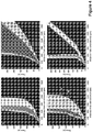
- Figure 3a, b shows the general device operation for dzlTP.
- the upper channel in Figure 3a, b is the separation channel; this is the channel where isotachophoretic zones are formed during the experiment.
- Three-point voltage actuation is utilized: to each of the access holes of the separation channel a voltage source is connected, while the other channel is connected to ground.
- concentration polarization takes place: an ion depletion zone forms in the separation channel, while in the other channel an ion enrichment zone forms (not shown here).
- Asymmetric voltage application over the separation channel yields an EOF through this channel.
- the channel arm between the higher voltage and the nanochannel is referred to as the "upstream channel”, while the arm between the lower voltage and the nanochannel is referred to as the “downstream channel” (see Figure 4a ).
- the depletion zone continues to grow until the fluid reservoir is reached. This process sometimes appears to lead to fluctuations during the first 30 to 60s of an experiment.
- depletion zone growth becomes balanced by the opposing EOF.
- the downstream depletion zone reaches the outlet, the electrical resistance in this channel reaches a more stable value, resulting in a near-stable position for the upstream depletion zone border.
- analytes are focused based on a difference in ion density (for detailed theory, see Zangle et al.35).
- the depletion zone serves here as a terminating electrolyte, and the background electrolyte takes the function of the leading electrolyte. They define the ionic mobility window of analytes that can be focused. The upper boundary of this mobility window is defined by the mobility of the leading ion in the background electrolyte: analytes with higher mobilities will be transported toward the reservoir. The lower boundary depends on the electric field in the depletion zone, which is very high. For example, Kim et al. measured a 30-fold amplified electric field in the depletion zone; see Langmuir 2009, 25, 7759-7765 . Only analytes with very low mobilities are transported through this barrier by EOF.
- the channels have a negative surface charge. Consequently, only anions are focused and separated at the depletion zone border.
- the surface charge of the device should be reversed by applying a surface coating or by choosing a different substrate.
- dzITP Discrete and Continuous Injections: dzITP was demonstrated for both discrete and continuous injections (see Figure 4a, b ). Fluorescein, 50 ⁇ mol/L, and 6-carboxyfluorescein, 50 ⁇ mol/L, were used as analytes; applied voltages were 120 V (upstream) and 40 V (downstream). For discrete injections, only the separation channel was filled with sample, while remaining channels and fluid reservoirs contained background electrolyte only. This resulted in a 309 pL injection volume, as calculated from the microchannel dimensions. Figure 4a shows that isotachophoretic separation continues until all analytes from the discrete sample are focused, after which the zone widths become constant.
- Zone broadening speed of the lower mobility compound (fluorescein) is higher than that of the higher mobility compound (6- carboxyfluorescein), again due to a higher net velocity.
- Continuous injections are therefore most advantageous for the extraction and focusing of low-concentration, low-mobility analytes, while discrete injections are useful in the quantitative analysis of multiple analytes.
- Figure 4c shows concentration and separation of four compounds.
- FIG. 4d A combination of a continuous and a discrete injection is shown in Figure 4d .
- the upstream fluid reservoir was filled with electrolyte containing 100 ⁇ mol/L sodium acetate as a spacer compound, but no analytes.
- the separation channel was filled with electrolyte containing 30 ⁇ mol/L of both fluorescein and 6-carboxyfluorescein as analytes, but no spacer compound.
- External voltages were 120 V (upstream) and 40 V (downstream).
- fluorescein and 6-carboxyfluorescein are focused in adjacent zones.
- acetate which has an ionic mobility in between that of fluorescein and 6-carboxyfluorescein, arrives and spaces the two compounds.
- the fluorescein zone remains focused at the depletion zone border, while the 6-carboxyfluorescein zone is pushed away in upstream direction by the continuously broadening acetate zone.
- Spacer addition enables baseline separation of fluorescent compounds enabling more precise identification and quantification. Furthermore, a single compound or a specific group of compounds can be selectively transported away from the depletion zone and can eventually be eluted from the system, while other compounds remain at their near-stationary position at the border of the depletion zone. Advantageously, all compounds remain focused during this process. Thus, spacer addition is a powerful method for purification and transport. Positional Stability. A crucial feature of dzITP is the positional stability of the depletion zone border. A near-stationary condition is reached after a rather short period, typically on the order of 100 s (see Figure 4 ), in which depletion rate and EOF velocity reach a balance.
- Figure 5 Three-Point Voltage Actuation: In Figure 5 applicants demonstrate the versatility that is provided by a three-point voltage actuation approach.
- Figure 5 a,b the magnitude of the upstream and downstream voltages was varied, while maintaining the ratio between them. This enables tuning of the extent to which analytes are focused. For low voltages the two zones are barely distinguishable, while for high voltages sharp edges of the zones can be observed.
- Figure 5b shows normalized slope values in fluorescence intensity per micrometer. The results suggest a linear trend between voltage magnitude and zone sharpness. Analyte zone positions are not greatly influenced by a change of the voltage magnitude as long as the ratio between upstream and downstream voltages is kept constant. In principle, this enables a free choice of the maximum field strength and resulting focusing strength.
- dzITP provides synergies that emerge from the combination of ITP and nanofluidic concentration devices, as provided by dzlTP. Except for the requirement of multiple electrolytes, dzITP has all key characteristics of ITP: focusing toward plateau concentrations and separation into adjacent zones t hat are ordered according to ionic mobility. Spacer compounds may be used to segregate adjacent zones. From nanofluidic concentration devices, dzITP takes the single electrolyte advantage, as well as positional stability. Three-point voltage actuation adds to this synergy the possibility of precise control of focusing strength and zone positioning.
- dzITP requires only a single electrolyte to be injected and can be performed easily with both discrete and continuous injections.
- a spacer was inserted to improve baseline separation of fluorescent compounds, and to induce selective transport of analytes while maintaining sharply focused zones.
- full control over analyte position and zone sharpness was demonstrated using the unique three-point voltage control of dzlTP.
- Scanning of analyte zones using three-point voltage actuation will enable simple integration of sensors such as surface-enhanced Raman spectroscopy (SERS), surface plasmon resonance (SPR), and conductimetry or electrochemical detection.
- SERS surface-enhanced Raman spectroscopy
- SPR surface plasmon resonance
- electrochemical detection As dzITP is much easier to use than conventional ITP, integration into a microfluidic platform for everyday laboratory use will be very attractive, as exemplified by the Agilent 2100 Bioanalyzer for on-chip capillary electrophoresis. Integration in hand-held analysis devices, as has been recently done for conventional ITP, see Kaigala, G. V. et al., Lab Chip 2010, 10, 2242-2250 , may find interesting applications in water quality monitoring, explosive detection, point-of-care screening, etc.
- Chips, Setup and Microscopy were as in Example 1.
- current actuation was performed via the electrode connected to the upstream (sample) reservoir, while the downstream reservoir was connected to a constant voltage.
- only one of the reservoirs of the bottom channel was connected to ground (see figure 5a ).
- the pulsed mode experiments figure 6
- both the upstream and downstream reservoir were connected to voltage sources, while both reservoirs of the bottom channel were connected to ground.
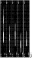
- RESULTS AND DISCUSSION Analyte Release: The filter is enabled by the fact that analytes in dzITP zones can be released along the depletion zone into the downstream part of the separation channel, as shown in figure 6 .
- a depletion zone is formed in the separation channel upon voltage actuation.
- the analyte, 150 ⁇ mol/L of fluorescein is focused at the upstream border of the depletion zone and forms an isotachophoretic zone. 2.5 mM lithium carbonate was used as the electrolyte.
- the fluorescein zone could be positioned at varying distances from the nanochannel by changing the ratio between the voltages and/or currents at the upstream and downstream fluid reservoirs.
- two laminar streams can be discerned, one containing ion-rich fluid from the upstream channel and one containing ion-depleted liquid resulting from the concentration polarization process over the nanochannel ( figure 6c ,d).
- the two streams Downstream from the nanochannel, the two streams rapidly mix through dispersion, forming a homogeneous dilution of the released analytes.
- the contribution of the fluorescein-rich fluid stream becomes much larger, resulting in a corresponding increase in the fluorescence intensity in the downstream channel.
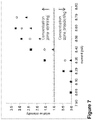
- the graph in figure 7 shows how the intensity of released fluorescein in the downstream channel depends on the applied current.
- a zone of concentrated fluorescein was established by conventional dzITP and subsequently released using different currents on the sample reservoir, while maintaining a constant voltage of 40V at the downstream reservoir.
- the results of three experimental series using the same conditions are shown, to indicate reproducibility.
- a threshold current can be derived from the graph.
- the threshold current was defined as the value for the current at the upstream fluid reservoir at which the analyte starts to be released (given a constant voltage at the downstream fluid reservoir).
- these threshold currents also can be estimated by interpolation of the point where fluorescence intensity becomes zero. These estimated values vary in the order of 2.5%. Even though between the experimental series the variation in threshold currents is quite small, the corresponding variations in fluorescence intensity are significant.
- Figure 8 shows how the dzITP filter is operated in order to collect compounds above a certain mobility cut-off while continuously releasing other compounds.
- fluorescein, 6-carboxyfluorescein and FITC-leucine each 50 ⁇ mol/L, were injected continuously by placing the sample solution in the upstream reservoir.
- a depletion zone was established and subsequently the current that was applied through the upstream reservoir was tuned just above the threshold current ( figure 8a ). This resulted in continuous release of analyte along the depletion zone.
- the flux of released analyte that was released was smaller than the flux of fluorescein that was supplied. Therefore, fluorescein was only partly released, while the concentrated zone continued to broaden.
- the filtering condition is (V): J fluorescein + J FITC-leucine ⁇ J release ⁇ J fluorescein + J FITC-leucine + J 6 ⁇ -carboxyfluorescein
- V J fluorescein + J FITC-leucine ⁇ J release ⁇ J fluorescein + J FITC-leucine + J 6 ⁇ -carboxyfluorescein
- the continuous filtering mode can be automated by setting the zone width of a specific, continuously injected "marker compound" to a predefined value, using a real-time image analysis algorithm as a feedback for applied voltages and currents. Such a procedure implies partial release of the marker compound.
- the ionic mobility of the marker compound precisely defines the ionic mobility cut-off of the dzITP filter: isotachophoretic principles guarantee that all ions with lower mobilities than the marker compound will be co-released while all higher mobility compounds will be focused and separated adjacent to the marker zone.
- the dzITP filtration is based on release along the depletion zone, yielding a temporary two-stream profile of analyte and depletion zone (see figures 6c and d).
- This mechanism is in contrast with another mechanism, in which compounds are released through the depletion zone. Release through the depletion zone occurs when the contribution of electrophoretic drift of compounds in the depletion zone is smaller than the electro-osmotic flow. This occurs for compounds with low ionic mobilities first.
- This mechanism is a probable explanation for the ion-selectivity observed in electro-capture devices, in which peptides and other compounds could be released sequentially across enrichment and depletion zones formed by concentration polarization.
- Figure 9 shows dzITP filtering in pulsed mode.
- a discrete amount of fluorescein (60 ⁇ mol/L), 6-carboxyfluorescein, FITC-leucine, and FITC-glutamate, (each 30 ⁇ mol/L) was injected by filling the separation channel with electrolyte plus sample solution, while the upstream "sample” reservoir contained electrolyte without sample.
- a depletion zone was established in the upstream part of the channel, at the border of which the analytes were focused. Fluorescein focused closest to the depletion zone border, followed by FITC-leucine, 6-carboxyfluorescein and finally FITC-glutamate.
- analytes can be released with regular time intervals to fractionate the dzITP-separation while accepting that a single compound might appear in multiple fractions, or that a single fraction contains multiple compounds.
- FIG 9 shows a proof of principle for the application of the dzITP filter to a complex biological sample, using fluorescein as a marker compound.
- a continuous dzITP injection was performed. Without low-pass filtering, fluorescein and undesired low-mobility compounds would accumulate, rapidly swamping the complete read-out window. Therefore, voltages were tuned such that a fluorescein zone was established with an approximately stable width. Behind this fluorescein zone, compounds from the urine sample formed several other zones ( figure 10a ). The zones are visualized by indirect detection. In isotachophoretic separations, each zone has its specific conductivity. The continuously injected fluorescein travels through these zones and co-adjusts its concentration to the local conductivity.
- the fluorescein thus is not only used as a marker, but also acts as tracer; (a so-called "underspeeder”).
- the fluorescence profile in figure 10b five putative analyte zones are indicated. As in each isotachophoretic separation, the zones have overlap at the borders. The putative zone borders are therefore indicated at the inflection points between the zones in the fluorescence profile. Theoretically, with this mode of indirect detection a staircase-like fluorescence profile is expected, with increasing fluorescence intensities for each zone closer to the fluorescein zone.
- zone III in figure 10b has significantly lower fluorescence intensity. Possibly, this zone contains an analyte which quenches fluorescence.
- the fluorescein marker and the carbonate electrolyte define a window of ionic mobilities, which contains only a limited number of metabolites out of the thousands of compounds in urine. These probably include only very small molecules or molecules that have, like fluorescein, at least a doubly negative charge.
- Notable metabolites that fulfil these conditions include acetate, aspartate, glutamate and several citric acid cycle products.
- the carbonate electrolyte defines the upper limit of the mobility window and excludes some small ions, particularly chloride.
- Low-mobility compounds are co-released with the fluorescein. It is probable that more than five urine metabolites are retained in the dzITP zones, however they might have very low concentrations and therefore are not forming individual zones, but rather focused in non-detectable peaks between the zones. For sample analysis it is therefore desirable to continue this continuous filtration step with a number of pulsed releases as described above. This way, fractions of enriched analytes can be sent to a detector located along the downstream channel for identification and quantification.
- the dzITP filter will be highly enabling, because it can be used to remove at least two undesired classes of compounds from ultra-small complex samples: proteins, which have lower mobility, and salts, which have higher mobilities than most metabolites.
- a device with two dzITP filters in series is employed, wherein salts can be trapped in the first filter, and metabolites in the second filter, while proteins are removed.
- Example 2 illustrates the potential of the dynamic low-pass filter that separates compounds based on ionic mobility according to a preferred embodiment of the invention.
- the dzITP filter advantageously works by voltage or current-controlled release of compounds along a nanochannel-induced depletion zone.
- dzITP-separated compounds are fractionated in plugs that are released sequentially along the depletion zone.
- a certain (marker) compound may be partially released, whereby the ionic mobility of this compound defines the cut-off of the filter.
- Compounds with lower mobility are co-released, compounds with higher mobility are trapped in isotachophoretic zones.
- this cut-off can be simply and rapidly tuned by voltage or current actuation. This in contrast to many other filtering techniques, which require modification of chemical or physical properties for tuning.
- the dzITP filter has been demonstrated with diluted raw urine sample, using fluorescein as a marker. Out of the thousands of compounds in urine, a small ionic mobility window was selected wherein five analyte zones were indirectly detected. The dzITP filter can thus enrich specific compounds from complex biological samples and enable real-time monitoring and detection.
Landscapes
- Health & Medical Sciences (AREA)
- Life Sciences & Earth Sciences (AREA)
- Molecular Biology (AREA)
- Chemical & Material Sciences (AREA)
- Chemical Kinetics & Catalysis (AREA)
- Electrochemistry (AREA)
- Physics & Mathematics (AREA)
- Analytical Chemistry (AREA)
- Biochemistry (AREA)
- General Health & Medical Sciences (AREA)
- General Physics & Mathematics (AREA)
- Immunology (AREA)
- Pathology (AREA)
- Investigating, Analyzing Materials By Fluorescence Or Luminescence (AREA)
Claims (15)
- Verfahren, um eine Vielzahl von in einer Probe enthaltenen geladenen Analyten durch Verarmungszonen-Isotachophorese in einer Vorrichtung zu konzentrieren, zu separieren und/oder zu isolieren, die mindestens umfasst: einen Haupttrennkanal (C), einen Elektrolyten, wobei der Kanal (C) ein stromabwärtiges Ende (D) und ein stromaufwärtiges Ende (U) und ein Verarmungszonen-Entwicklungsmittel (N) aufweist, das in einem Zwischenbereich zwischen dem stromaufwärtigen Ende und dem stromabwärtigen Ende angeordnet oder mit diesem verbunden ist, wobei das Verfahren diese Schritte umfasst:(i) die Probe an einem stromaufwärtigen Kanalbereich neben dem stromaufwärtigen Ende (U) in den Elektrolyten einbringen und(ii) im Trennkanal (C) und neben den Verarmungszonen-Entwicklungsmitteln unter Verwendung der Verarmungszonen-Entwicklungsmittel eine ionenverarmte Zone bei einer Verarmungsrate (R) bilden und/oder aufrechterhalten und(iii) zwischen dem stromabwärtigen Ende (D) und dem stromaufwärtigen Ende (U) ein elektrisches Feld (Ê1) und eine stromabwärtige Fluidströmung (F) anlegen, wodurch die Analyten fokussiert und getrennt werden bzw. entsprechend fokussierte Analyten-Zonen im Trennkanal (C) und neben der ionenarmen Zone gebildet werden und(iv) gegebenenfalls die Position und/oder Zusammensetzung der fokussierten Zonen erfassen und(v) die Verarmungsrate (R) und gegebenenfalls die Fluidströmung (F) einstellen, um mindestens eine fokussierte Analysesubstanz-Zone in eine stromaufwärtige und/oder stromabwärtige Richtung zu bewegen und/odereine oder mehrere fokussierte Analysesubstanz-Zonen an einer gewünschten Position im Trennkanal (C) positionieren.
- Verfahren gemäß Anspruch 1, wobei ein zweites elektrisches Feld (Ê2) über den Verarmungszonen-Entwicklungsmitteln (N) vorhanden ist, die die Verarmungsraten (R) und/oder die Position von mindestens einer fokussierten Analyten-Zone kontrollieren.
- Verfahren gemäß Anspruch 1 oder Anspruch 2, wobei das Verarmungszonen-Entwicklungsmittel (N) eine semipermeable Membran, eine Nanopore oder ein Nanokanal ist und wobei die Bildung der ionenarmen Zone durch Ionenkonzentrationspolarisation induziert wird, wobei das Verarmungszonen-Entwicklungsmittel (N) gegebenenfalls ein Nanokanal ist, der das stromaufwärtige und das stromabwärtige Ende des Kanals (C) stömungstechnisch verbindet.
- Verfahren gemäß einem der vorhergehenden Ansprüche, wobei die Längsströmung (F) eine elektroosmotische Strömung, eine durch Druck erzeugte Strömung oder eine Kombination davon ist.
- Verfahren gemäß einem der vorhergehenden Ansprüche, wobei Schritt (v) umfasst, das elektrische Feld (Ê1) und/oder (Ê2) und/oder die durch Druck erzeugte Strömung zu variieren.
- Verfahren gemäß einem der vorhergehenden Ansprüche, wobei das elektrische Feld (Ê1) und/oder (Ê2) durch Strom- oder Spannungsquellen oder eine Kombination davon, vorzugsweise durch Anlegen einer Dreipunktspannungsdifferenz über der Vorrichtung, gesteuert werden.
- Verfahren gemäß einem der vorhergehenden Ansprüche, wobei das Vorhandensein oder Fehlen eines fokussierten Analyten und/oder dessen sofortige Konzentration in (iii) elektrisch, thermisch oder optisch erkannt wird, wobei die elektrische Detektion gegebenenfalls durch Messen eines Strom- oder Widerstandsplateaus erfolgt oder wobei die optische Detektion durch Fluoreszenz-, Emissions- oder Absorptionsspektroskopie erfolgt.
- Verfahren gemäß einem der vorhergehenden Ansprüche, wobei die Probe zumindest einen ersten und einen zweiten fokussierten und getrennten Analyten enthält und wobei der erste Analyt relativ zum zweiten Analyten stromabwärts positioniert ist, wobei das Verfahren ferner den Schritt umfasst, die Position des zweiten Analyten so einzustellen, dass die erste Analyten-Zone teilweise oder vollständig in eine stromabwärtige Richtung entlang der ionenarmen Zone transportiert wird, wobei der erste Analyt gegebenenfalls ein Markermolekül ist, das zum direkten oder indirekten Nachweis eines Reaktionsprodukts und/oder einer reichlich vorhandenen Verbindung geeignet ist, wobei der erste Analyt gegebenenfalls zur weiteren Analyse zu einem Nachweismittel (u.a. Massenspektroskopie, Raman-IR-Spektroskopie) oder zu einer Rückgewinnungskammer, wie einem Phytotron oder einer Sammelkammer transportiert wird.
- Verfahren gemäß einem der vorhergehenden Ansprüche, wobei die Position von mindestens einer Analyten-Zone oder deren Grenze durch einen Sensor erfasst wird, wobei der Sensor gegebenenfalls ein Teil eines Steuersystems ist, das die Position von mindestens einer Analyten-Zone oder deren Grenze misst, wobei das Steuersystem gegebenenfalls einen geschlossenen Regelkreis umfasst.
- Verfahren gemäß einem der vorhergehenden Ansprüche, umfassend eine Vorrichtung zu verwenden, die mehrere Verarmungszonen-Entwicklungsmittel umfasst.
- Verfahren gemäß einem der Ansprüche 1 bis 10, wobei ein Extraktionskanal (E) an der Verbindungsstelle mit dem stromabwärtigen Ende des Kanals (C) vorgesehen ist, das in Bezug auf den Haupttrennkanal (C) quer ausgerichtet ist und ein Extraktionsteil aufweist, das aus dem Haupttrennkanal herausführt; und wobei eine Transversalströmung angelegt wird, wenn ein fokussiertes Analysesubstanz-Band die Verbindungsstelle zwischen Kanal (C) und Extraktionskanal (E) erreicht hat.
- Verfahren gemäß einem der Ansprüche 1 bis 11, wobei neben der Probe ein oder mehrere weitere Spacer-Verbindungen (S) vorhanden sind.
- Vorrichtung zum Vorkonzentrieren und Isolieren mehrerer in einer Probe enthaltener geladener Analyten durch Verarmungszonen-Isotachophorese umfassend:(a) einen Haupttrennkanal (C) mit einem Elektrolyten, wobei der Kanal (C) ein stromaufwärtiges Ende (U) und ein stromabwärtiges Ende (D) aufweist und(b) ein Verarmungszonen-Entwicklungsmittel (N), das in einem Zwischenbereich zwischen dem stromaufwärtigen Ende und dem stromabwärtigen Ende angeordnet ist und gegebenenfalls(c) einen Extraktionskanal (E) mit einer Verbindung zum Hauptkanal an der stromabwärtigen Seite des Verarmungszonen-Entwicklungsmittels (N), das in Bezug auf den Haupttrennkanal (C) quer ausgerichtet ist und ein Extraktionsteil aufweist, das aus dem Haupttrennkanal herausführt,(d) Mittel, um eine Probe in ein internes Segment des Haupttrennkanals einzuführen, das sich zwischen dem stromaufwärtigen Ende (U) und dem stromabwärtigen Ende (D) befindet;(e) Mittel, um ein erstes elektrisches Feld (Ê1) zwischen dem stromaufwärtigen Ende (U) und dem stromabwärtigen Ende (D) anzulegen und(f) Mittel, um ein zweites elektrisches Feld (Ê2) über dem Verarmungszonen-Entwicklungsmittel (N) anzulegen; und(g) Mittel, um eine Strömung entlang der Längsrichtung des Haupttrennkanals anzulegen;(h) gegebenenfalls Mittel, um fokussierte Spacer-Zonen und/oder fokussierte Analyten-Zonen im Trennkanal (C) und/oder in den Verarmungszonen-Entwicklungsmitteln (N) zu erfassen;(i) gegebenenfalls Mittel, um die Strömungsgeschwindigkeit entlang einer Längsachse des Trennkanals zu messen; und(v) Mittel, um die Verarmungsrate (R) und gegebenenfalls die Fluidströmung (F) einzustellen, um mindestens eine fokussierte Analyten-Zone in eine stromaufwärtige und/oder stromabwärtige Richtung zu bewegen und/odereine oder mehrere fokussierte Analyten-Zonen an einer gewünschten Position im Trennkanal (C) positionieren.
- Vorrichtung gemäß Anspruch 13, wobei das Verarmungszonen-Entwicklungsmittel (N) gegebenenfalls ein Nanokanal ist, der das stromabwärtige und das stromaufwärtige Ende des Kanals (C) strömungstechnisch verbindet.
- Vorrichtung gemäß einem der Ansprüche 13 bis 14, wobei der Extraktionskanal (E) eine Sammelzone umfasst, die sich an einem Ende des Extraktionsteils befindet und/oder Mittel, um das elektrische Feld (Ê1) und/oder (Ê2) und/oder die durch Druck erzeugte Strömung zu variieren, wobei der Extraktionskanal (E) gegebenenfalls ferner ein Einspritzteil umfasst, das zur Verwaltung einer Transversalströmung in den Haupttrennkanal führt.
Applications Claiming Priority (2)
| Application Number | Priority Date | Filing Date | Title |
|---|---|---|---|
| US201261691560P | 2012-08-21 | 2012-08-21 | |
| PCT/NL2013/050608 WO2014030997A1 (en) | 2012-08-21 | 2013-08-21 | Apparatus and process for depletion zone isotachophoresis |
Publications (2)
| Publication Number | Publication Date |
|---|---|
| EP2888581A1 EP2888581A1 (de) | 2015-07-01 |
| EP2888581B1 true EP2888581B1 (de) | 2020-04-08 |
Family
ID=49151289
Family Applications (1)
| Application Number | Title | Priority Date | Filing Date |
|---|---|---|---|
| EP13759862.9A Active EP2888581B1 (de) | 2012-08-21 | 2013-08-21 | Vorrichtung und verfahren für verarmungszonenisotachophorese |
Country Status (3)
| Country | Link |
|---|---|
| US (1) | US9575031B2 (de) |
| EP (1) | EP2888581B1 (de) |
| WO (1) | WO2014030997A1 (de) |
Families Citing this family (9)
| Publication number | Priority date | Publication date | Assignee | Title |
|---|---|---|---|---|
| EP3916090B1 (de) | 2016-01-29 | 2025-07-23 | Purigen Biosystems, Inc. | Isotachophorese zur reinigung von nukleinsäuren |
| US10775345B2 (en) * | 2016-10-27 | 2020-09-15 | Arkray, Inc. | Analytical method and analytical system |
| US20200110054A1 (en) * | 2017-04-03 | 2020-04-09 | Technion Research & Development Foundation Limited | Microfluidic devices and methods using the same |
| US11364499B2 (en) * | 2017-05-15 | 2022-06-21 | Technion Research & Development Foundation Limited | Devices and methods for improved single-molecule detection |
| US10669572B2 (en) | 2017-05-31 | 2020-06-02 | University Of Notre Dame Du Lac | Ultra-sensitive multi-target lateral flow molecular assay with field-induced precipitation |
| KR20190006719A (ko) | 2017-07-11 | 2019-01-21 | 광주과학기술원 | 진단 키트, 진단 방법 및 진단 장치 |
| SG11202000871WA (en) * | 2017-08-02 | 2020-02-27 | Purigen Biosystems Inc | Systems, devices, and methods for isotachophoresis |
| KR102092230B1 (ko) * | 2019-06-25 | 2020-03-23 | 광주과학기술원 | 진단 키트, 진단 방법 및 진단 장치 |
| AU2022264249A1 (en) * | 2021-04-30 | 2023-10-26 | University Of Tasmania | Sample transfer method and system |
Family Cites Families (7)
| Publication number | Priority date | Publication date | Assignee | Title |
|---|---|---|---|---|
| SE390766B (sv) * | 1972-12-19 | 1977-01-17 | Lkb Produkter Ab | Forfarande vid motflodesisotachofores |
| US5817225A (en) | 1996-08-16 | 1998-10-06 | Exxon Research And Engineering Company | Electrophoresis system for the purification, concentration and size fractionation of nucleic acids |
| US20020189946A1 (en) | 2000-02-11 | 2002-12-19 | Aclara Biosciences, Inc. | Microfluidic injection and separation system and method |
| EP2541239B1 (de) * | 2003-09-05 | 2019-05-01 | Caliper Life Sciences, Inc. | Verfahren zur Isotachophorese |
| JP2006317357A (ja) | 2005-05-13 | 2006-11-24 | Shimadzu Corp | マイクロチップ電気泳動方法及び装置 |
| US8080144B2 (en) * | 2006-10-04 | 2011-12-20 | The United States of America as represented by the Secretary of Commerce, the National Institute of Standards and Technology | Gradient elution electrophoresis |
| WO2009079028A1 (en) | 2007-12-14 | 2009-06-25 | Johns Hopkins University | Purification and concentration of proteins and dna from a complex sample using isotachophoresis and a device to perform the purification |
-
2013
- 2013-08-21 US US14/422,736 patent/US9575031B2/en active Active
- 2013-08-21 WO PCT/NL2013/050608 patent/WO2014030997A1/en not_active Ceased
- 2013-08-21 EP EP13759862.9A patent/EP2888581B1/de active Active
Non-Patent Citations (1)
| Title |
|---|
| None * |
Also Published As
| Publication number | Publication date |
|---|---|
| EP2888581A1 (de) | 2015-07-01 |
| US20150219594A1 (en) | 2015-08-06 |
| US9575031B2 (en) | 2017-02-21 |
| WO2014030997A1 (en) | 2014-02-27 |
Similar Documents
| Publication | Publication Date | Title |
|---|---|---|
| EP2888581B1 (de) | Vorrichtung und verfahren für verarmungszonenisotachophorese | |
| JP6750084B2 (ja) | 検体の解析方法 | |
| Garcia et al. | Electrokinetic molecular separation in nanoscale fluidic channels | |
| Son et al. | Engineered nanofluidic preconcentration devices by ion concentration polarization | |
| JP5323933B2 (ja) | 増幅動電流体のポンプ供給切り換えおよび脱塩 | |
| Johnson et al. | Micro free flow electrophoresis | |
| CA2595840C (en) | Electrokinetic concentration device and methods of use thereof | |
| US8585883B2 (en) | Isotachophoretic analyte extraction | |
| Yue et al. | Novel multi-depth microfluidic chip for single cell analysis | |
| Jung et al. | Detection of 100 aM fluorophores using a high-sensitivity on-chip CE system and transient isotachophoresis | |
| Kelly et al. | Phase-changing sacrificial materials for interfacing microfluidics with ion-permeable membranes to create on-chip preconcentrators and electric field gradient focusing microchips | |
| Louër et al. | Pressure-assisted selective preconcentration in a straight nanochannel | |
| Quist et al. | Tunable ionic mobility filter for depletion zone isotachophoresis | |
| Zhao et al. | Droplet-based in situ compartmentalization of chemically separated components after isoelectric focusing in a Slipchip | |
| KR101749600B1 (ko) | 샘플 농축 장치 및 이를 이용하여 농축된 샘플 추출 방법 | |
| Esene et al. | High-performance microchip electrophoresis separations of preterm birth biomarkers using 3D printed microfluidic devices | |
| Quist et al. | Single-electrolyte isotachophoresis using a nanochannel-induced depletion zone | |
| US20200061616A1 (en) | Electrokinetically separating, encapsulating and extracting analytes on a microfluidic device | |
| Aïzel et al. | Electropreconcentration of nanoparticles using a radial micro-nanofluidic device | |
| US20230381778A1 (en) | Devices, systems, and methods related to nucleic acid isolation | |
| Gou et al. | Multi-CEM-embedded microfluidic system for simultaneous molecular enrichment and separation by multi-stage ion concentration polarization | |
| Anwar et al. | An integrated micro-nanofluidic system for sample preparation and preconcentration of proteins | |
| Quist | Single-electrolyte isotachophoresis: on-chip analyte focusing and separation | |
| Anwar et al. | An integrated micro/nanofluidic system for processing of protein samples | |
| Park et al. | Combined On-Chip Ion-Concentration Polarization-Based Biomolecule Preconcentration and Solution Exchange Operations Toward Enhanced Biosensing |
Legal Events
| Date | Code | Title | Description |
|---|---|---|---|
| PUAI | Public reference made under article 153(3) epc to a published international application that has entered the european phase |
Free format text: ORIGINAL CODE: 0009012 |
|
| 17P | Request for examination filed |
Effective date: 20150305 |
|
| AK | Designated contracting states |
Kind code of ref document: A1 Designated state(s): AL AT BE BG CH CY CZ DE DK EE ES FI FR GB GR HR HU IE IS IT LI LT LU LV MC MK MT NL NO PL PT RO RS SE SI SK SM TR |
|
| AX | Request for extension of the european patent |
Extension state: BA ME |
|
| DAX | Request for extension of the european patent (deleted) | ||
| GRAP | Despatch of communication of intention to grant a patent |
Free format text: ORIGINAL CODE: EPIDOSNIGR1 |
|
| STAA | Information on the status of an ep patent application or granted ep patent |
Free format text: STATUS: GRANT OF PATENT IS INTENDED |
|
| GRAJ | Information related to disapproval of communication of intention to grant by the applicant or resumption of examination proceedings by the epo deleted |
Free format text: ORIGINAL CODE: EPIDOSDIGR1 |
|
| GRAP | Despatch of communication of intention to grant a patent |
Free format text: ORIGINAL CODE: EPIDOSNIGR1 |
|
| INTG | Intention to grant announced |
Effective date: 20191007 |
|
| INTG | Intention to grant announced |
Effective date: 20191017 |
|
| GRAS | Grant fee paid |
Free format text: ORIGINAL CODE: EPIDOSNIGR3 |
|
| GRAA | (expected) grant |
Free format text: ORIGINAL CODE: 0009210 |
|
| STAA | Information on the status of an ep patent application or granted ep patent |
Free format text: STATUS: THE PATENT HAS BEEN GRANTED |
|
| AK | Designated contracting states |
Kind code of ref document: B1 Designated state(s): AL AT BE BG CH CY CZ DE DK EE ES FI FR GB GR HR HU IE IS IT LI LT LU LV MC MK MT NL NO PL PT RO RS SE SI SK SM TR |
|
| REG | Reference to a national code |
Ref country code: AT Ref legal event code: REF Ref document number: 1255075 Country of ref document: AT Kind code of ref document: T Effective date: 20200415 Ref country code: CH Ref legal event code: EP |
|
| REG | Reference to a national code |
Ref country code: DE Ref legal event code: R096 Ref document number: 602013067710 Country of ref document: DE |
|
| REG | Reference to a national code |
Ref country code: IE Ref legal event code: FG4D |
|
| REG | Reference to a national code |
Ref country code: NL Ref legal event code: FP |
|
| REG | Reference to a national code |
Ref country code: CH Ref legal event code: NV Representative=s name: DR. LUSUARDI AG, CH |
|
| REG | Reference to a national code |
Ref country code: LT Ref legal event code: MG4D |
|
| PG25 | Lapsed in a contracting state [announced via postgrant information from national office to epo] |
Ref country code: FI Free format text: LAPSE BECAUSE OF FAILURE TO SUBMIT A TRANSLATION OF THE DESCRIPTION OR TO PAY THE FEE WITHIN THE PRESCRIBED TIME-LIMIT Effective date: 20200408 Ref country code: NO Free format text: LAPSE BECAUSE OF FAILURE TO SUBMIT A TRANSLATION OF THE DESCRIPTION OR TO PAY THE FEE WITHIN THE PRESCRIBED TIME-LIMIT Effective date: 20200708 Ref country code: SE Free format text: LAPSE BECAUSE OF FAILURE TO SUBMIT A TRANSLATION OF THE DESCRIPTION OR TO PAY THE FEE WITHIN THE PRESCRIBED TIME-LIMIT Effective date: 20200408 Ref country code: LT Free format text: LAPSE BECAUSE OF FAILURE TO SUBMIT A TRANSLATION OF THE DESCRIPTION OR TO PAY THE FEE WITHIN THE PRESCRIBED TIME-LIMIT Effective date: 20200408 Ref country code: PT Free format text: LAPSE BECAUSE OF FAILURE TO SUBMIT A TRANSLATION OF THE DESCRIPTION OR TO PAY THE FEE WITHIN THE PRESCRIBED TIME-LIMIT Effective date: 20200817 Ref country code: GR Free format text: LAPSE BECAUSE OF FAILURE TO SUBMIT A TRANSLATION OF THE DESCRIPTION OR TO PAY THE FEE WITHIN THE PRESCRIBED TIME-LIMIT Effective date: 20200709 Ref country code: IS Free format text: LAPSE BECAUSE OF FAILURE TO SUBMIT A TRANSLATION OF THE DESCRIPTION OR TO PAY THE FEE WITHIN THE PRESCRIBED TIME-LIMIT Effective date: 20200808 |
|
| REG | Reference to a national code |
Ref country code: AT Ref legal event code: MK05 Ref document number: 1255075 Country of ref document: AT Kind code of ref document: T Effective date: 20200408 |
|
| PG25 | Lapsed in a contracting state [announced via postgrant information from national office to epo] |
Ref country code: RS Free format text: LAPSE BECAUSE OF FAILURE TO SUBMIT A TRANSLATION OF THE DESCRIPTION OR TO PAY THE FEE WITHIN THE PRESCRIBED TIME-LIMIT Effective date: 20200408 Ref country code: BG Free format text: LAPSE BECAUSE OF FAILURE TO SUBMIT A TRANSLATION OF THE DESCRIPTION OR TO PAY THE FEE WITHIN THE PRESCRIBED TIME-LIMIT Effective date: 20200708 Ref country code: HR Free format text: LAPSE BECAUSE OF FAILURE TO SUBMIT A TRANSLATION OF THE DESCRIPTION OR TO PAY THE FEE WITHIN THE PRESCRIBED TIME-LIMIT Effective date: 20200408 Ref country code: LV Free format text: LAPSE BECAUSE OF FAILURE TO SUBMIT A TRANSLATION OF THE DESCRIPTION OR TO PAY THE FEE WITHIN THE PRESCRIBED TIME-LIMIT Effective date: 20200408 |
|
| PG25 | Lapsed in a contracting state [announced via postgrant information from national office to epo] |
Ref country code: AL Free format text: LAPSE BECAUSE OF FAILURE TO SUBMIT A TRANSLATION OF THE DESCRIPTION OR TO PAY THE FEE WITHIN THE PRESCRIBED TIME-LIMIT Effective date: 20200408 |
|
| REG | Reference to a national code |
Ref country code: DE Ref legal event code: R097 Ref document number: 602013067710 Country of ref document: DE Ref country code: DE Ref legal event code: R082 Ref document number: 602013067710 Country of ref document: DE Representative=s name: HL KEMPNER PATENTANWALT, RECHTSANWALT, SOLICIT, DE Ref country code: DE Ref legal event code: R082 Ref document number: 602013067710 Country of ref document: DE Representative=s name: HL KEMPNER PATENTANWAELTE, SOLICITORS (ENGLAND, DE Ref country code: DE Ref legal event code: R082 Ref document number: 602013067710 Country of ref document: DE Representative=s name: HL KEMPNER PARTG MBB, DE |
|
| PG25 | Lapsed in a contracting state [announced via postgrant information from national office to epo] |
Ref country code: DK Free format text: LAPSE BECAUSE OF FAILURE TO SUBMIT A TRANSLATION OF THE DESCRIPTION OR TO PAY THE FEE WITHIN THE PRESCRIBED TIME-LIMIT Effective date: 20200408 Ref country code: IT Free format text: LAPSE BECAUSE OF FAILURE TO SUBMIT A TRANSLATION OF THE DESCRIPTION OR TO PAY THE FEE WITHIN THE PRESCRIBED TIME-LIMIT Effective date: 20200408 Ref country code: SM Free format text: LAPSE BECAUSE OF FAILURE TO SUBMIT A TRANSLATION OF THE DESCRIPTION OR TO PAY THE FEE WITHIN THE PRESCRIBED TIME-LIMIT Effective date: 20200408 Ref country code: RO Free format text: LAPSE BECAUSE OF FAILURE TO SUBMIT A TRANSLATION OF THE DESCRIPTION OR TO PAY THE FEE WITHIN THE PRESCRIBED TIME-LIMIT Effective date: 20200408 Ref country code: CZ Free format text: LAPSE BECAUSE OF FAILURE TO SUBMIT A TRANSLATION OF THE DESCRIPTION OR TO PAY THE FEE WITHIN THE PRESCRIBED TIME-LIMIT Effective date: 20200408 Ref country code: ES Free format text: LAPSE BECAUSE OF FAILURE TO SUBMIT A TRANSLATION OF THE DESCRIPTION OR TO PAY THE FEE WITHIN THE PRESCRIBED TIME-LIMIT Effective date: 20200408 Ref country code: AT Free format text: LAPSE BECAUSE OF FAILURE TO SUBMIT A TRANSLATION OF THE DESCRIPTION OR TO PAY THE FEE WITHIN THE PRESCRIBED TIME-LIMIT Effective date: 20200408 Ref country code: EE Free format text: LAPSE BECAUSE OF FAILURE TO SUBMIT A TRANSLATION OF THE DESCRIPTION OR TO PAY THE FEE WITHIN THE PRESCRIBED TIME-LIMIT Effective date: 20200408 |
|
| PLBE | No opposition filed within time limit |
Free format text: ORIGINAL CODE: 0009261 |
|
| STAA | Information on the status of an ep patent application or granted ep patent |
Free format text: STATUS: NO OPPOSITION FILED WITHIN TIME LIMIT |
|
| PG25 | Lapsed in a contracting state [announced via postgrant information from national office to epo] |
Ref country code: PL Free format text: LAPSE BECAUSE OF FAILURE TO SUBMIT A TRANSLATION OF THE DESCRIPTION OR TO PAY THE FEE WITHIN THE PRESCRIBED TIME-LIMIT Effective date: 20200408 Ref country code: SK Free format text: LAPSE BECAUSE OF FAILURE TO SUBMIT A TRANSLATION OF THE DESCRIPTION OR TO PAY THE FEE WITHIN THE PRESCRIBED TIME-LIMIT Effective date: 20200408 |
|
| 26N | No opposition filed |
Effective date: 20210112 |
|
| PG25 | Lapsed in a contracting state [announced via postgrant information from national office to epo] |
Ref country code: MC Free format text: LAPSE BECAUSE OF FAILURE TO SUBMIT A TRANSLATION OF THE DESCRIPTION OR TO PAY THE FEE WITHIN THE PRESCRIBED TIME-LIMIT Effective date: 20200408 |
|
| PG25 | Lapsed in a contracting state [announced via postgrant information from national office to epo] |
Ref country code: LU Free format text: LAPSE BECAUSE OF NON-PAYMENT OF DUE FEES Effective date: 20200821 |
|
| PG25 | Lapsed in a contracting state [announced via postgrant information from national office to epo] |
Ref country code: SI Free format text: LAPSE BECAUSE OF FAILURE TO SUBMIT A TRANSLATION OF THE DESCRIPTION OR TO PAY THE FEE WITHIN THE PRESCRIBED TIME-LIMIT Effective date: 20200408 |
|
| PG25 | Lapsed in a contracting state [announced via postgrant information from national office to epo] |
Ref country code: TR Free format text: LAPSE BECAUSE OF FAILURE TO SUBMIT A TRANSLATION OF THE DESCRIPTION OR TO PAY THE FEE WITHIN THE PRESCRIBED TIME-LIMIT Effective date: 20200408 Ref country code: MT Free format text: LAPSE BECAUSE OF FAILURE TO SUBMIT A TRANSLATION OF THE DESCRIPTION OR TO PAY THE FEE WITHIN THE PRESCRIBED TIME-LIMIT Effective date: 20200408 Ref country code: CY Free format text: LAPSE BECAUSE OF FAILURE TO SUBMIT A TRANSLATION OF THE DESCRIPTION OR TO PAY THE FEE WITHIN THE PRESCRIBED TIME-LIMIT Effective date: 20200408 |
|
| PG25 | Lapsed in a contracting state [announced via postgrant information from national office to epo] |
Ref country code: MK Free format text: LAPSE BECAUSE OF FAILURE TO SUBMIT A TRANSLATION OF THE DESCRIPTION OR TO PAY THE FEE WITHIN THE PRESCRIBED TIME-LIMIT Effective date: 20200408 |
|
| P01 | Opt-out of the competence of the unified patent court (upc) registered |
Effective date: 20230602 |
|
| PGFP | Annual fee paid to national office [announced via postgrant information from national office to epo] |
Ref country code: NL Payment date: 20250822 Year of fee payment: 13 |
|
| PGFP | Annual fee paid to national office [announced via postgrant information from national office to epo] |
Ref country code: DE Payment date: 20250822 Year of fee payment: 13 |
|
| PGFP | Annual fee paid to national office [announced via postgrant information from national office to epo] |
Ref country code: BE Payment date: 20250825 Year of fee payment: 13 Ref country code: GB Payment date: 20250822 Year of fee payment: 13 |
|
| PGFP | Annual fee paid to national office [announced via postgrant information from national office to epo] |
Ref country code: FR Payment date: 20250822 Year of fee payment: 13 |
|
| PGFP | Annual fee paid to national office [announced via postgrant information from national office to epo] |
Ref country code: CH Payment date: 20250901 Year of fee payment: 13 |
|
| PGFP | Annual fee paid to national office [announced via postgrant information from national office to epo] |
Ref country code: IE Payment date: 20250822 Year of fee payment: 13 |