EP2888954B2 - Dispositif pour écarter plus de deux rubans de matière d'enveloppement pour obtenir au moins deux tiges parallèles des produits de tabac et une machine ayant ledit dispositif pour écarter - Google Patents
Dispositif pour écarter plus de deux rubans de matière d'enveloppement pour obtenir au moins deux tiges parallèles des produits de tabac et une machine ayant ledit dispositif pour écarter Download PDFInfo
- Publication number
- EP2888954B2 EP2888954B2 EP14184043.9A EP14184043A EP2888954B2 EP 2888954 B2 EP2888954 B2 EP 2888954B2 EP 14184043 A EP14184043 A EP 14184043A EP 2888954 B2 EP2888954 B2 EP 2888954B2
- Authority
- EP
- European Patent Office
- Prior art keywords
- wrapping material
- spreading device
- pivot
- material web
- coupling bars
- Prior art date
- Legal status (The legal status is an assumption and is not a legal conclusion. Google has not performed a legal analysis and makes no representation as to the accuracy of the status listed.)
- Active
Links
Images



Classifications
-
- A—HUMAN NECESSITIES
- A24—TOBACCO; CIGARS; CIGARETTES; SIMULATED SMOKING DEVICES; SMOKERS' REQUISITES
- A24C—MACHINES FOR MAKING CIGARS OR CIGARETTES
- A24C5/00—Making cigarettes; Making tipping materials for, or attaching filters or mouthpieces to, cigars or cigarettes
- A24C5/14—Machines of the continuous-rod type
- A24C5/20—Reels; Supports for bobbins; Other accessories
-
- B—PERFORMING OPERATIONS; TRANSPORTING
- B65—CONVEYING; PACKING; STORING; HANDLING THIN OR FILAMENTARY MATERIAL
- B65H—HANDLING THIN OR FILAMENTARY MATERIAL, e.g. SHEETS, WEBS, CABLES
- B65H23/00—Registering, tensioning, smoothing or guiding webs
- B65H23/02—Registering, tensioning, smoothing or guiding webs transversely
- B65H23/022—Registering, tensioning, smoothing or guiding webs transversely by tentering devices
- B65H23/025—Registering, tensioning, smoothing or guiding webs transversely by tentering devices by rollers
- B65H23/0251—Registering, tensioning, smoothing or guiding webs transversely by tentering devices by rollers with a straight axis
-
- B—PERFORMING OPERATIONS; TRANSPORTING
- B65—CONVEYING; PACKING; STORING; HANDLING THIN OR FILAMENTARY MATERIAL
- B65H—HANDLING THIN OR FILAMENTARY MATERIAL, e.g. SHEETS, WEBS, CABLES
- B65H2301/00—Handling processes for sheets or webs
- B65H2301/40—Type of handling process
- B65H2301/41—Winding, unwinding
- B65H2301/414—Winding
- B65H2301/4148—Winding slitting
-
- B—PERFORMING OPERATIONS; TRANSPORTING
- B65—CONVEYING; PACKING; STORING; HANDLING THIN OR FILAMENTARY MATERIAL
- B65H—HANDLING THIN OR FILAMENTARY MATERIAL, e.g. SHEETS, WEBS, CABLES
- B65H2402/00—Constructional details of the handling apparatus
- B65H2402/30—Supports; Subassemblies; Mountings thereof
-
- B—PERFORMING OPERATIONS; TRANSPORTING
- B65—CONVEYING; PACKING; STORING; HANDLING THIN OR FILAMENTARY MATERIAL
- B65H—HANDLING THIN OR FILAMENTARY MATERIAL, e.g. SHEETS, WEBS, CABLES
- B65H2801/00—Application field
- B65H2801/54—Cigarette making
Definitions
- the invention relates to a spreading device for two or more wrapping material webs for the production of at least two parallel strands of products of the tobacco processing industry with the features of the preamble of claim 1 and a system with a spreading device with the features of the preamble of claim 17.
- a spreading device for two or more wrapping material webs for the production of at least two parallel strands of products of the tobacco processing industry with the features of the preamble of claim 1 and a system with a spreading device with the features of the preamble of claim 17.
- Such a device is the end EP-A-0 309 818 known.
- both the strand-like filter material and the strand of loose tobacco fibers are fixed by means of a sheet of wrapping material.
- a wrapping material web of multiple, in particular double, widths is first unwound from a reel and cut into two or more wrapping material webs aligned parallel to one another in a continuous cutting process.
- the cutting device is formed by a pull-cutting roller assembly in which the multiple-width wrapping material web is cut into two or more wrapping material webs of identical width.
- the parallel wrapping material webs are then offset parallel to one another by means of a spreading device, so that they then run parallel and at a distance from one another. This is necessary in particular because the strands then also run in the strand forming unit at a distance and parallel to one another.
- Such a spreading device which comprises a number of deflection roller groupings corresponding to the number of wrapping material webs, each of which is traversed by a wrapping material web in such a way that the wrapping material web is deflected when entering the bottom of the first deflecting roller and then on the top of the second deflecting roller.
- the deflection rollers are inclined relative to the deflected wrapping material webs, so that the wrapping material webs are laterally offset in parallel during the deflection.
- the spreading distance of the wrapping material webs after passage can be changed by adjusting the height of the second deflection rollers.
- the deflection roller groupings each comprise two deflection rollers, which are each arranged in pairs on a common support frame.
- the spreading distance of the wrapping material webs is changed in this solution in that the support frame is pivoted together with the deflection rollers about an axis of rotation running parallel to the feed direction through the center of the first deflection roller.
- the deflection rollers are mounted free-floating on one side, so that the wrapping material webs can be threaded into the deflection roller groupings from the side of the free ends of the deflection rollers.
- the deflection rollers of the deflection roller groupings through which the wrapping material webs pass are arranged in relation to one another in such a way that the free ends of the deflection rollers face one another and are spaced apart from one another.
- both wrapping material webs can be threaded into the deflection roller groupings between the deflection rollers.
- the invention is based on the object of providing a spreading device or a system with a spreading device, in which the threading of the wrapping material webs is easier to handle.
- the threading process of the wrapping material webs can be considerably simplified by the arrangement of the deflection roller groupings offset in the transport direction, since the access is considerably simplified.
- the wrapping material webs are introduced into the deflection roller grouping offset in relation to the transport direction and laterally offset in parallel in the deflecting roller groupings.
- the wrapping material webs run from the point at which the first wrapping material web enters the first deflection roller grouping to the point in which the last wrapping material web from the deflection roller grouping emerges, the same distance, so that no stresses are introduced into the advance of the wrapping material webs.
- the parallel lateral offset of the wrapping material webs can be designed to be much more individual than was possible with a conventional spreading device with oppositely arranged deflection roller groups. In the extreme case, it would even be conceivable to offset the wrapping material webs on top of one another so that they then at least partially overlap in an edge section.
- the deflection roller groupings are arranged one above the other in the manner of a terrace.
- the proposed arrangement makes the pulley groupings accessible from the side in a particularly simple and easy-to-use manner for threading the wrapping strip.
- the threading in is particularly easy if the deflection rollers are mounted free-floating on one side, so that the guide track for the wrapping strip is open on the side.
- the deflection rollers in each case of a deflection roller grouping have an identical diameter and an identical relative angle to one another.
- the first and the second deflection rollers of a deflection roller grouping accordingly have an identical diameter and are each aligned with the incoming wrapping material web in such a way that the deflection rollers of the individual deflection roller groupings have an identical relative angle to one another, ie the relative angle between the respective first deflection roller and the respective second deflection roller of the different pulley groupings is identical in each case.
- the relative angle is the angle difference between the longitudinal axes or axes of rotation of the deflection rollers of a deflection roller grouping in the projection in the transport direction, which is the cause of the lateral offset of the wrapping material webs, so that this is also identical in the result for the individual deflection roller groupings.
- the advantage of the proposed solution is that the deflection and the change in angle of the wrapping material web caused by the relative angle between the inlet section and the outlet section on the deflection rollers of the different deflection roller groupings are identical.
- the deflection is also dependent on the diameter of the deflection rollers, which is also identical due to the identical diameter.
- the distances between the deflection rollers in each of the deflection roller groupings are identical for the different deflection roller groupings.
- the distance covered by the wrapping material webs when passing through the pulley groupings is identical, so that no additional stresses are introduced into the wrapping material webs by the spreading device, namely neither in the leading nor in the trailing edge of the wrapping material webs.
- the pulley groupings are identical and designed or aligned with mirror symmetry, so that the wrapping material webs are laterally offset by an identical distance.
- the feed and discharge directions of the wrapping material webs towards and away from the deflection roller groupings are aligned parallel to one another. Due to the parallel alignment of the wrapping material webs in the feed and the discharge direction, the wrapping material web run can be made even more uniform, in that the parallel run of the wrapping material webs further reduces the likelihood of stresses occurring in the wrapping material webs. As a result, the course of the wrapping material webs can be controlled particularly precisely, which is particularly advantageous for controlling the edge position of the wrapping material webs.
- deflection roller groupings can each be pivoted about a pivot axis running through the wrapping material web resting on the first deflection roller.
- the pivot axis lies exactly in the longitudinal center line of the wrapping material web, so that the wrapping material web is pivoted laterally to the center line by the same angle and in the same width when the deflection roller grouping is adjusted.
- the deflection roller groupings are each adjustable by means of an adjusting device formed by a multi-joint mechanism. Due to the multi-joint mechanism, the entire group of deflection rollers can be pivoted particularly easily about the virtual pivot axis arranged in the wrapping material web, with the adjustment movement of a linear drive device also being able to be converted into a pivot movement in a particularly simple manner. This can be achieved in a particularly simple manner in that the multi-joint mechanism which transmits the adjustment movement has a forced guidance which defines the pivot axis. The positive guidance is formed by various joints which, through their spacing from one another, specify the sequence of movements during the pivoting movement.
- the multi-joint mechanism transmitting the adjustment movement is preferably mounted with two first coupling rods in two stationary pivot bearings, the stationary pivot bearings preferably being arranged in such a way that their pivot axes lie on a straight line which runs through the wrapping material web adjacent to the first deflection roller.
- first coupling rods are preferably coupled to one another via at least two second coupling rods, each of which has a support plate at its ends a pivot bearing is pivotally mounted, wherein the pulleys are arranged on the support plate.
- the second coupling rods are each mounted in pivot bearings opposite the first coupling rods, and at least the pivot bearings closest to the stationary pivot bearings are arranged between the first and second coupling rods in such a way that they are at a distance from the stationary pivot bearings perpendicular to the transport direction of the wrapping material web have, which corresponds to the distance between the pivot axis of the wrapping material web and the closest pivot bearing between the support plate and one of the second coupling rods perpendicular to the transport direction of the wrapping material web.
- the distance between the pivot axis and the closest pivot bearing between the support plate and one of the second coupling rods perpendicular to the transport direction of the wrapping material web is the distance between the stationary pivot bearings and the closest pivot bearings between the coupling rods and the distance between the pivot axis and the closest one Pivot bearing between the support plate and one of the second coupling rods corresponds to the transport direction of the wrapping material web.
- the second coupling rods are each mounted in pivot bearings opposite the first coupling rods, and the distance between the pivot bearings of the second coupling rods corresponds to the distance between the stationary pivot bearings.
- the second coupling rods are each mounted in pivot bearings opposite the first coupling rods, and the distance between the stationary pivot bearing closest to the pivot axis of the wrapping material web and the pivot axis of the wrapping material web is the distance between the pivot bearing between the support plate and one of the second coupling rods, which is closest to the pivot axis, corresponds to the pivot bearing between one of the first and second coupling rod, which is arranged closest to the stationary pivot bearing.
- the proposed arrangement of the swivel bearings and the dimensioning of the distances between the swivel bearings enables the wrapping material web to be swiveled about a swivel axis running in the wrapping material web, which enables the edge position of the wrapping material web to be controlled very precisely with very little tension in the leading and trailing edge of the wrapping material web can be.
- this can prevent the wrapping material web from running laterally on the deflecting roller during the pivoting so far that the pivot axis of the wrapping material web runs outside the wrapping material web.
- the deflection roller groupings are adjustable by means of a drive device coupled to the second coupling rods.
- the proposed solution is advantageous in that the drive device can thereby be arranged and fastened at a distance from the deflection roller groupings without this having disadvantages for the adjustment accuracy, since the second coupling rods are connected directly to the support plates on which the deflection rollers are held .
- a system with a spreading device according to claim 15 is proposed to achieve the object, the system having a partition, the spreading device extending through the partition, and the deflection roller groupings on an operator side of the partition, and the drive device being arranged on a drive side of the partition are.
- the proposed partition and the arrangement of the pulley groupings can protect the operator from unintentional interference with the drive devices and the associated gear mechanism for transmitting the drive movement, e.g. while threading the wrapping material webs.
- the drive device, the gear mechanism and the corresponding part of the multi-joint mechanism can be protected from external mechanical influences on the part of the operator. For the operator, only the pulley groupings for threading the wrapping material webs are deliberately accessible.
- the partition has recesses, and the multi-joint mechanism extends through the recesses of the partition with the second coupling rods, and the first coupling rods of the multi-joint mechanism are arranged on the drive side and the support plates of the multi-joint mechanism are arranged on the operator side of the partition.
- a spreading device can be seen schematically from the side.
- a wrapping material web 1 of multiple, in this case double, width is fed to the spreading device from a reel, not shown, and is cut in a pull-cutting roller grouping 10 into two parallel wrapping material webs 2 and 3 of single width.
- the wrapping material webs 2 and 3 immediately adjacent to one another after cutting are then fed to two deflection roller groups 4 and 5 arranged offset from one another in the transport direction of the wrapping material webs 2 and 3.
- the wrapping material web 2 at the front in the illustration is first introduced into the first deflection roller grouping 4, and at the top of the first deflection roller 6 down to the underside of the second deflection roller 8 and then again from the underside of the second deflection roller 8.
- the feed directions I and III of the wrapping material webs 2 and 3 and the discharge directions II and IV are both in the vertical plane of the representation of the Fig. 1 as well as in the horizontal plane of the representation of the Fig. 2 aligned parallel to each other.
- the second rear wrapping material web 3 is only deflected in a second deflection roller grouping 5 with two deflection rollers 7 and 9 after it has covered a distance, that is to say offset in the transport direction.
- the two deflecting rollers 7 and 9 of the second deflecting roller grouping 5 and the two deflecting rollers 6 and 8 of the first deflecting roller grouping 4 are aligned at an identical distance from one another and have an identical diameter.
- first deflection rollers 6 and 7 and the second deflection rollers 8 and 9 are each aligned at an identical relative angle to one another, so that the wrapping material webs 2 and 3 cover the same distance when passing through the deflection roller groupings 4 and 5 and the same distance when the deflection roller groupings are mirror-symmetrical be offset laterally in parallel.
- the wrapping material webs 2 and 3 are each deflected twice in the deflection roller groupings 4 and 5, and pivoted in opposite directions due to the inclinations of the deflection rollers 6, 7, 8 and 9.
- the angles of the pulleys 6, 7, 8 and 9 to the wrapping material webs are selected so that the wrapping material webs are each offset outwards by approximately the same amount, so that the distance between the wrapping material webs 2 and 3 is then the sum of the lateral offset movements, and in the ideal case, in the case of a symmetrical offset movement, this corresponds to the double offset movement of a wrapping material web 2 or 3.
- the angles of the first deflection rollers 6 and 7 and the second deflection rollers 8 and 9 are aligned mirror-symmetrically to one another in pairs, so that in the basic position of the spreading device there is an identical offset of the wrapping material webs 2 and 3 outwards, i.e. perpendicular to the transport direction.
- the wrapping material webs 2 and 3 are guided past a sensor device 11 that senses the edge position and then introduced via a threading device 12 into a strand forming unit (not shown) in which, for example, a strand of loose tobacco fibers is applied to the wrapping material webs 2 and 3 is launched.
- Fig. 2 is the spreader from the Fig. 1 visible from above.
- the multiple-width wrapping material web 1 is cut in the pull-cutting roller grouping 10 into two parallel single-width wrapping material webs 2 and 3. After cutting, the wrapping material webs 2 and 3 are fed diagonally towards the viewer in the illustration.
- the wrapping material web 2 which is lower in the illustration, is introduced into the first deflection roller grouping 4 and deflected on the upper side of the first deflection roller 6 to the underside of the second deflection roller 8.
- the upper wrapping material web 3 is offset in the transport direction, that is, after having covered a short distance on the first deflection roller 7 of the second deflection roller group 5, it is deflected again on the upper side of the first deflection roller 7 to the underside of the second deflection roller 9.
- the angles A of the first deflection rollers 6 and 7 to the feed directions I and III and the angles B of the second deflection rollers 8 and 9 to the discharge directions II and IV of the wrapping material webs 2 and 3 are each identical, so that the feed and discharge directions I.
- wrapping material webs 2 and 3 are also deflected around the circumferences of the deflection rollers 6,7,8 and 9 by the same circumferential angle, the wrapping material webs 2 and 3 are also in the feed direction I and III and the discharge direction II and IV in the side view of Fig. 1 aligned parallel to each other.
- the pulley groupings 4 and 5 are offset from one another in relation to the transport direction of the wrapping material webs 2 and 3, so that they are arranged one above the other in a terrace-like manner due to the inclined upwardly directed course of the wrapping material webs 2 and 3. Since the pulley groupings 4 and 5 are offset from one another, the wrapping material webs 2 and 3 can be introduced laterally much more easily, since the pulley groupings 4 and 5 are now accessible from the side. The improved accessibility is achieved in particular by the terrace-like arrangement of the pulley groupings 4 and 5, since the pulley groupings 4 and 5 thereby laterally no longer cover.
- the terrace-like arrangement is achieved here by a correspondingly large deflection of the wrapping material web 2 at the first deflection roller 6 of the first deflection roller grouping 4 in the circumferential direction and by correspondingly dimensioning the distance covered by the second wrapping material web 3 before entering the second deflection roller grouping 4.
- the pulleys 6, 7, 8 and 9 in the pulley groupings 4 and 5 are each mounted free-floating on one side, so that the guideways of the wrapping material webs 2 and 3 in the pulley groupings 4 and 5 are open at the sides, and the wrapping material webs 4 and 5 are very easily pushed in laterally can be.
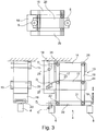
- the adjustment mechanism is formed by a multi-joint mechanism, which in the Fig. 3 can be seen from different views.
- the multi-joint mechanism comprises a plurality of coupling rods 14, 15, 16, 17 and 29, which are pivotably connected to one another in joints 23, 24, 25 and 26. Furthermore, the multi-joint mechanism is fastened with the ends of the coupling rods 14, 15 and 29 in pivot bearings 27 and 28 on a holder 18 fixed to the machine.
- the deflection rollers 6 and 8 are mounted on one side so as to be free-floating on a support plate 20, which in turn is held pivotably at the free ends of the coupling rods 16 and 17. Furthermore, a linear drive device 19 is provided which is connected to the end of the support plate 20 which is remote from the first deflection roller 6.
- the multi-joint mechanism is designed and in particular has such a forced guidance that the linear drive movement of the drive device 19 is converted into a pivoting movement of the entire multi-joint mechanism with a pivot axis C tangent to the surface of the first deflection roller 6.
- the angle of the deflecting rollers 6 and 8 can be changed relative to the wrapping material web 2 deflected thereon, the pivot axis C ideally lying in the wrapping material web 2, preferably in the central longitudinal axis of the wrapping material web 2, so that despite the pivoting of the first deflecting roller 6 there are no tensions in the wrapping material web 2 and also no stresses are introduced into the multiple width wrapping material web 1 in advance. So that the pivot axis C is tangent to the surface of the deflecting roller 6, it is important that the center points of the pivot bearings 27 and 28 on the machine-fixed holder 18 are arranged on a straight connecting line tangent to the surface of the deflecting roller 6.
- the straight line connecting the center points of the pivot bearings 27 and 28 does not run tangentially through the surface of the deflection roller 6 after pivoting, but instead approximately through the pivot axis C.
- the pivot bearings 27 and 28 on the holder 18 must be as follows be arranged so that the distances D of the centers of the pivot bearings 27 and 28 from the centers of the pivot bearings 23 and 25 in the projection in the direction of the connecting straight line correspond to the distance D between the center of the pivot bearing 22 and the pivot axis C in the direction of the connecting straight line.
- deflection roller groups 4 and 5 can be pivoted independently of one another, while a common adjusting device would also be conceivable for a pure change in the spreading distance.
- the feed directions I and III of the wrapping material webs 2 and 3 are shown in FIG Fig. 2 can be seen from above by the dashed lines, which in this case are at the same time the center lines of the wrapping material webs 2 and 3.
- the center lines of the wrapping material webs 2 and 3 run parallel to one another and are spaced apart from one another corresponding to the single width of the wrapping material webs 2 or 3.
- the wrapping material webs 2 and 3 are laterally offset outwards so that they are then aligned parallel to one another at a greater distance, which can be seen by the dashed lines of the discharge directions II and IV.
- the deflection roller groupings 4 and 5 have deflection rollers 6 and 8 or 7 and 9 with an identical distance from one another, an identical diameter and an identical relative angle to one another.
- the wrapping material webs 2 and 3 in the deflection roller groupings 4 and 5 run an identical distance, and are offset symmetrically outwards by the same distance apart from the offset in the transport direction with an identical mirror-symmetrical alignment of the deflection roller groupings 4 and 5.
- Fig. 4 the required distances of the pivot bearings 27,28,21,22,23,24,25 and 26 to each other and to the pivot axis C of the wrapping material web 2 are shown in more detail, which must be observed so that the forced guidance in a linear adjustment movement to pivot the wrapping material web 2 around the pivot axis C.
- the distances are described below in the position of the non-pivoted deflection roller grouping, ie the coupling rods 14 and 15 or 16 and 17 are aligned in pairs parallel to one another, and the first coupling rods 14, 15 are aligned perpendicular to the second coupling rods 16, 17.
- the following described Distances relate in each case to the pivot centers or the pivot axes of the pivot bearings 27, 28, 21, 22, 23, 24, 25 and 26, which correspond to the center axis of the bearing pin in the case of a journal bearing. If another type of pivot bearing is to be implemented, the distances must instead be related to the pivot center of the pivot bearing. To simplify the understanding of the invention, the distances are only generally defined as the distances between the pivot bearings 27, 28, 21, 22, 23, 24, 25 and 26, which actually mean the respective pivot axes.
- the one already in the Fig. 3 Distance D described should correspond approximately to the width of the wrapping material web 2 or 3 to be pivoted.
- the distance E between the centers of the pivot bearings 22, 23 and 25 in the transport direction of the wrapping material webs 2 and 3 should approximately correspond to the distance D.
- the distances D and E are thus approximately 30 mm.
- the distance F of the center points of the pivot bearings 21, 24, 26 to the centers of the pivot bearings 22, 23 and 25 should be significantly greater than the distance E, in particular the distance F should be 4 to 10 times as large as the distance E.
- the distances G between the centers of the pivot bearings 21 and 24 and between the center of the pivot bearing 27 and the pivot axis C in the projection perpendicular to the transport direction of the wrapping material webs 2 and 3 should be identical and approximately 1.5 times the distance D.
- the distance H between the centers of the pivot bearings 23 and 25 should also be identical to the distance, also identified as H, between the centers of the pivot bearings 27 and 28, which should also be approximately twice the distance D.
- one of the pivot bearings 23, 24, 25 or 26 can be omitted, with the omission of the pivot bearing 26 being particularly useful.
- additional stability and rigidity can also be introduced into the multi-joint mechanism. Since the adjustment movements tend to be seen at smaller adjustment angles, the increased rigidity is not a disadvantage for the adjustment movement.
- the proposed solution can ensure that the pivot axis C of the wrapping material web 2 remains in the wrapping material web 2 during the pivoting of the deflection roller grouping 4 and does not run out of it.
- the deflection roller 6 with the adjacent wrapping material web 2 and the pivot axis C arranged therein can be moved slightly in the transport direction or against the transport direction of the wrapping material web 2.
- the pivot axis C in the wrapping material web 2 can also wander slightly laterally out of the longitudinal center axis of the wrapping material web. It is only important that the pivot axis C remains in the wrapping material web 2 so that stresses are only introduced into the leading and trailing of the wrapping material web 2 in a negligible order of magnitude.
- the edge position of the wrapping material web 2 can be regulated much more precisely and the wrapping material web run is much smoother and more controlled.
- the distances D are identical and the distances E identical so that the pivot axis C of the adjustment movement runs approximately in the wrapping material web 2 or 3 resting on the first deflection rollers 6 and 7.
- the radius of the adjustment movement corresponds to the distance between the pivot bearings 25 and 28 or between the pivot bearings 23 and 27, which corresponds to the distance between the pivot axis C and the pivot bearing 22.
- the pivot axis C is placed at least significantly closer to the wrapping material webs 2 or 3 resting on the first deflection rollers 6 or 7 than was possible with the solutions known in the prior art.
- the course of the wrapping material webs 2 and 3 can be regulated much more precisely and made much quieter.
- the multi-joint mechanism described represents, regardless of the offset arrangement of the deflection roller groupings 4 and 5 or the terrace-like arrangement of the same due to the reduced stresses in the wrapping material webs 2 and 3, a significant improvement in the wrapping material web run and the edge control of the wrapping material webs 2 or 3, and can thus be used as a independent inventive idea.
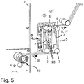
- a further developed spreading device can be seen, which has an identical multi-joint mechanism and two deflection roller groupings 4 and 5, which have already been described.
- the further developed solution differs from the embodiment of FIG Fig. 3 in that the drive device 19 is formed here by two independently controllable servomotors which are each connected via an eccentric gear 30 to a coupling rod 16 of the multi-joint mechanisms assigned to the deflection roller groups 4 and 5.
- Each of the deflection roller groupings 4 and 5 is assigned its own multi-joint mechanism designed according to the invention, so that the deflection roller groupings 4 and 5 can be adjusted separately from one another via their own coupling rod 16.
- the rear deflection roller grouping 5 clearly has its own and identical multi-joint mechanism which, for the sake of clarity, has not been provided with reference symbols.
- a partition 31 with one or more recesses 34 is provided, which separates an operator side 32 from a drive side 33.
- the Spreader reaches through the recesses 34 with the coupling rods 16 and 17, so that the pulley groupings 4 and 5 are arranged on the operator side 32 of the partition 31, while the servomotors, the eccentric gear 30, the coupling rods 14 and 15 and the coupling rods 16 and 17 with the the recesses 34 non-penetrating sections are arranged on the drive side 33 of the system.
- the operator can be protected intrinsically from unintentional intervention in the multi-joint mechanisms and the servomotors on the drive side 33.
- the components arranged on the drive side 33 can be protected from mechanical influences from the operator side 32.
- the servomotors are connected via the eccentric gears 30 to the ends of the coupling rods 16, which drive the drive movement through the recesses 34 of the partition 31 onto the support plates 20 arranged on the operator's side or the deflection rollers 6 held on them, 7,8 or 9 transferred.
- the servomotors can thereby be arranged at a distance from the support plates 20 arranged on the operator side 32 and the deflection rollers 6, 7, 8 and 9 on the drive side 33.
- the pulley groupings 4 and 5 are also offset from one another in the transport direction of the wrapping material webs 2 and 3, the pulley groupings 4 and 5 not being arranged in a terraced manner here, but instead being arranged in an approximately vertical orientation of the support plates 20 at a distance next to one another.
Landscapes
- Adjustment And Processing Of Grains (AREA)
- Preliminary Treatment Of Fibers (AREA)
- Rolls And Other Rotary Bodies (AREA)
- Absorbent Articles And Supports Therefor (AREA)
- Treatment Of Fiber Materials (AREA)
Claims (17)
- Dispositif d'écartement de deux bandes ou plus de matière d'enveloppement (2, 3) pour obtenir au moins deux tiges parallèles de produits de l'industrie de traitement du tabac, comportant- un nombre de groupements de rouleaux de renvoi (4, 5) correspondant au nombre de bandes de matière d'enveloppement (2, 3), avec respectivement des rouleaux de renvoi (6, 7, 8, 9) individuels, sur lesquels une bande de matière d'enveloppement (2, 3) est respectivement renvoyée sur des côtés différents, dans lequel- les rouleaux de renvoi (6, 7, 8, 9) sont inclinés de telle manière que la bande de matière d'enveloppement (2, 3) renvoyée sur ceux-ci sort du groupement de rouleaux de renvoi (4, 5) de manière latéralement décalée en parallèle par rapport à une direction d'alimentation (I, III), dans lequel- les groupements de rouleaux de renvoi (4, 5) sont disposés de manière décalée les uns par rapport aux autres dans la direction de transport des bandes de matière d'enveloppement (2, 3),caractérisé en ce que- les groupements de rouleaux de renvoi (4, 5) peuvent pivoter respectivement sur un axe de pivotement (C) s'étendant à travers la bande de matière d'enveloppement (2, 3) en contact avec le premier rouleau de renvoi (6, 7).
- Dispositif d'écartement selon la revendication 1, caractérisé en ce que- les groupements de rouleaux de renvoi (4, 5) sont disposés en terrasses les uns au-dessus des autres.
- Dispositif d'écartement selon l'une des revendications précédentes, caractérisé en ce que- les rouleaux de renvoi (6, 7, 8, 9) d'un groupement de rouleaux de renvoi (4, 5) respectif présentent un diamètre identique et un angle relatif entre eux identique.
- Dispositif d'écartement selon l'une des revendications précédentes, caractérisé en ce que- les écarts entre les rouleaux de renvoi (6, 7, 8, 9) dans un groupement de rouleaux de renvoi (4, 5) respectif sont identiques pour les différents groupements de rouleaux de renvoi (4, 5).
- Dispositif d'écartement selon l'une des revendications précédentes, caractérisé en ce que- la direction d'alimentation (I, III) et la direction de sortie (II, IV) des bandes de matière d'enveloppement (2, 3) vers les groupements de rouleaux de renvoi (4, 5) et s'éloignant de ceux-ci sont orientées de manière parallèle entre elles.
- Dispositif d'écartement selon l'une des revendications précédentes, caractérisé en ce que- l'axe de pivotement (C) s'étend à travers l'axe médian longitudinal de la bande de matière d'enveloppement (2, 3).
- Dispositif d'écartement selon l'une des revendications précédentes, caractérisé en ce que- les groupements de rouleaux de renvoi (4, 5) peuvent être réglés respectivement au moyen d'un moyen de réglage formé par un mécanisme à articulations multiples.
- Dispositif d'écartement selon la revendication 7, caractérisé en ce que- le mécanisme à articulations multiples transmettant le mouvement de réglage est monté avec deux premières barres de couplage (14, 15) dans deux supports de pivotement (27, 28) fixes.
- Dispositif d'écartement selon la revendication 8, caractérisé en ce que- les supports de pivotement (27, 28) fixes sont disposés de telle manière que leurs axes de pivotement se trouvent sur une droite qui s'étend à travers la bande de matière d'enveloppement (2, 3) en contact avec le premier rouleau de renvoi (6, 7).
- Dispositif d'écartement selon l'une des revendications 8 ou 9, caractérisé en ce que- les premières barres de couplage (14, 15, 29) sont couplées entre elles par le biais d'au moins deux secondes barres de couplage (16, 17), aux extrémités desquelles une plaque de support (20) est montée de manière pivotante respectivement dans un support de pivotement (21, 22), dans lequel- les rouleaux de renvoi (6, 7, 8, 9) sont disposés sur la plaque de support (20).
- Dispositif d'écartement selon la revendication 10, caractérisé en ce que- les secondes barres de couplage (16, 17) sont montées respectivement dans des supports de pivotement (23, 24, 25, 26) de manière opposée par rapport aux premières barres de couplage (14, 15, 29), et- au moins les supports de pivotement (23, 25) les plus proches des supports de pivotement (27, 28) fixes entre les premières et secondes barres de couplage (14, 15, 16, 17, 29) sont disposés de telle manière qu'ils présentent un écart (D) par rapport aux supports de pivotement (27, 28) fixes, perpendiculairement à la direction de transport de la bande de matière d'enveloppement (2, 3), qui correspond à l'écart (D) entre l'axe de pivotement (C) de la bande de matière d'enveloppement (2) et le support de pivotement (22) le plus proche entre la plaque de support (20) et l'une des secondes barres de couplage (16, 17), perpendiculairement à la direction de transport de la bande de matière d'enveloppement (2).
- Dispositif d'écartement selon la revendication 10 ou 11, caractérisé en ce que- l'écart (D) entre l'axe de pivotement (C) et le support de pivotement (22) le plus proche entre la plaque de support (20) et l'une des secondes barres de couplage (16, 17), perpendiculairement à la direction de transport de la bande de matière d'enveloppement (2), correspond à l'écart (E) entre les supports de pivotement (27, 28) fixes et les supports de pivotement (23, 25) les plus proches entre les barres de couplage (14, 15, 16, 17, 29) et à l'écart (E) entre l'axe de pivotement (C) et le support de pivotement (22) le plus proche entre la plaque de support (20) et l'une des secondes barres de couplage (16, 17) dans la direction de transport de la bande de matière d'enveloppement (2).
- Dispositif d'écartement selon l'une des revendications 10 à 12, caractérisé en ce que- les secondes barres de couplage (16, 17) sont montées respectivement dans des supports de pivotement (23, 24, 25, 26) de manière opposée par rapport aux premières barres de couplage (14, 15, 29), et- l'écart (H) entre les supports de pivotement (23, 24, 25, 26) des secondes barres de couplage (16, 17) correspond à l'écart (H) entre les supports de pivotement (27, 28) fixes.
- Dispositif d'écartement selon l'une des revendications 10 à 13, caractérisé en ce que- les secondes barres de couplage (16, 17) sont montées respectivement dans des supports de pivotement (23, 24, 25, 26) de manière opposée par rapport aux premières barres de couplage (14, 15, 29), et- l'écart (G) entre le support de pivotement (27) fixe le plus proche de l'axe de pivotement (C) de la bande de matière d'enveloppement (2) et l'axe de pivotement (C) de la bande de matière d'enveloppement (2) correspond à l'écart (G) entre le support de pivotement (22) entre la plaque de support (20) et l'une des secondes barres de couplage (16, 17), qui est le plus proche de l'axe de pivotement (C), et le support de pivotement (23) entre l'une des premières et secondes barres de couplage (14, 15, 16, 17, 29), qui est disposé le plus proche du support de pivotement (27) fixe.
- Dispositif d'écartement selon l'une des revendications 10 à 14, caractérisé en ce que- les groupements de rouleaux de renvoi (4, 5) peuvent être réglés à l'aide d'un moyen d'entraînement (19) couplé aux secondes barres de couplage (16, 17).
- Machine comportant un dispositif d'écartement selon la revendication 15, caractérisée en ce que- la machine comporte une paroi de séparation (31),- le dispositif d'écartement s'étend à travers la paroi de séparation (31), et- les groupements de rouleaux de renvoi (4, 5) sont disposés d'un côté utilisateur (32) de la paroi de séparation (31), et- le moyen d'entraînement (19) est disposé d'un côté entraînement (33) de la paroi de séparation (31).
- Machine selon la revendication 16, caractérisée en ce que- la paroi de séparation (31) comporte des évidements (34), et- le mécanisme à articulations multiples traverse les évidements (34) de la paroi de séparation (31) avec les secondes barres de couplage (16, 17), et- les premières barres de couplage (14, 15) du mécanisme à articulations multiples sont disposées du côté entraînement (33), et- les plaques de support (20) du mécanisme à articulations multiples sont disposées du côté utilisateur (32) de la paroi de séparation (31).
Priority Applications (1)
| Application Number | Priority Date | Filing Date | Title |
|---|---|---|---|
| PL14184043T PL2888954T5 (pl) | 2013-09-10 | 2014-09-09 | Urządzenie rozstawiające dla dwóch lub więcej wstęg materiału owijkowego do wytwarzania co najmniej dwóch równoległych pasm produktów przemysłu tytoniowego i instalacja z urządzeniem rozstawiającym |
Applications Claiming Priority (1)
| Application Number | Priority Date | Filing Date | Title |
|---|---|---|---|
| DE102013218097.7A DE102013218097A1 (de) | 2013-09-10 | 2013-09-10 | Spreizvorrichtung für zwei oder mehr Hüllmaterialbahnen zur Herstellung von wenigstens zwei parallelen Strängen von Produkten der Tabak verarbeitenden Industrie |
Publications (3)
| Publication Number | Publication Date |
|---|---|
| EP2888954A1 EP2888954A1 (fr) | 2015-07-01 |
| EP2888954B1 EP2888954B1 (fr) | 2016-11-02 |
| EP2888954B2 true EP2888954B2 (fr) | 2021-09-01 |
Family
ID=51518599
Family Applications (1)
| Application Number | Title | Priority Date | Filing Date |
|---|---|---|---|
| EP14184043.9A Active EP2888954B2 (fr) | 2013-09-10 | 2014-09-09 | Dispositif pour écarter plus de deux rubans de matière d'enveloppement pour obtenir au moins deux tiges parallèles des produits de tabac et une machine ayant ledit dispositif pour écarter |
Country Status (4)
| Country | Link |
|---|---|
| EP (1) | EP2888954B2 (fr) |
| CN (1) | CN104413543B (fr) |
| DE (1) | DE102013218097A1 (fr) |
| PL (1) | PL2888954T5 (fr) |
Families Citing this family (2)
| Publication number | Priority date | Publication date | Assignee | Title |
|---|---|---|---|---|
| DE102015001714A1 (de) * | 2015-02-13 | 2016-08-18 | Hauni Maschinenbau Ag | Vorrichtung zur Herstellung von Produkten der Tabak verarbeitenden Industrie |
| DE102017106992A1 (de) | 2017-03-31 | 2018-10-04 | Hauni Maschinenbau Gmbh | Verfahren zum Herstellen von wenigstens doppellagigen rohrförmigen Strängen der Tabak verarbeitenden Industrie sowie Vorrichtung zur Herstellung von wenigstens doppellagigen Strängen der Tabak verarbeitenden Industrie |
Citations (3)
| Publication number | Priority date | Publication date | Assignee | Title |
|---|---|---|---|---|
| DE3913700C1 (en) † | 1989-04-26 | 1990-11-15 | Erhardt + Leimer Gmbh, 8900 Augsburg, De | Tracking system for moving strip - uses two rollers on common support with self-aligning bearings on vertical pivots |
| US5398702A (en) † | 1991-12-19 | 1995-03-21 | G.D Societa' Per Azioni | Method of simultaneously producing two continuous streams of cigarettes |
| DE19846894A1 (de) † | 1998-10-13 | 2000-04-20 | Topack Verpacktech Gmbh | Vorrichtung zum Längstrennen einer Materialbahn |
Family Cites Families (8)
| Publication number | Priority date | Publication date | Assignee | Title |
|---|---|---|---|---|
| US4201132A (en) | 1978-04-28 | 1980-05-06 | Maschinenfabrik Peter Zimmer Aktiengesellschaft | Method of an apparatus for equalizing longitudinal stresses in an advancing web |
| IT1199385B (it) * | 1984-02-23 | 1988-12-30 | Gd Spa | Dispositivo di alimentazione di nastri di materiale d'incarto ad una macchina confezionatrice di sigarette del tipo a doppio baco |
| DE3733129C2 (de) | 1987-10-01 | 1999-02-18 | Focke & Co | Vorrichtung zum Trennen einer Materialbahn in zwei Teilbahnen |
| IT1285503B1 (it) * | 1996-01-31 | 1998-06-08 | Gd Spa | Metodo per l'incarto di prodotti |
| US5813337A (en) * | 1996-06-05 | 1998-09-29 | Quad/Tech, Inc. | Closed-loop printing control system |
| DE10044577A1 (de) | 2000-09-08 | 2002-03-21 | Hauni Maschinenbau Ag | Verfahren und Vorrichtung zum Trennen einer doppeltbreiten Ausgangs-Hüllmaterialbahn in zwei Teilbahnen |
| CN1231155C (zh) * | 2001-06-08 | 2005-12-14 | 日本烟草产业株式会社 | 带状材料的供给装置 |
| ITBO20020096A1 (it) * | 2002-02-27 | 2003-08-27 | Gd Spa | Metodo e dispositivo per l'alimentazione di elementi in foglio ad unalinea di incarto di prodotti |
-
2013
- 2013-09-10 DE DE102013218097.7A patent/DE102013218097A1/de not_active Withdrawn
-
2014
- 2014-09-09 PL PL14184043T patent/PL2888954T5/pl unknown
- 2014-09-09 EP EP14184043.9A patent/EP2888954B2/fr active Active
- 2014-09-09 CN CN201410454448.0A patent/CN104413543B/zh active Active
Patent Citations (3)
| Publication number | Priority date | Publication date | Assignee | Title |
|---|---|---|---|---|
| DE3913700C1 (en) † | 1989-04-26 | 1990-11-15 | Erhardt + Leimer Gmbh, 8900 Augsburg, De | Tracking system for moving strip - uses two rollers on common support with self-aligning bearings on vertical pivots |
| US5398702A (en) † | 1991-12-19 | 1995-03-21 | G.D Societa' Per Azioni | Method of simultaneously producing two continuous streams of cigarettes |
| DE19846894A1 (de) † | 1998-10-13 | 2000-04-20 | Topack Verpacktech Gmbh | Vorrichtung zum Längstrennen einer Materialbahn |
Also Published As
| Publication number | Publication date |
|---|---|
| PL2888954T3 (pl) | 2017-04-28 |
| EP2888954B1 (fr) | 2016-11-02 |
| EP2888954A1 (fr) | 2015-07-01 |
| CN104413543A (zh) | 2015-03-18 |
| DE102013218097A1 (de) | 2015-03-12 |
| PL2888954T5 (pl) | 2021-11-22 |
| CN104413543B (zh) | 2018-09-04 |
Similar Documents
| Publication | Publication Date | Title |
|---|---|---|
| DE69112429T2 (de) | Klebstoffspender. | |
| EP3046839B1 (fr) | Dispositif de fabrication d'unités d'emballage | |
| EP2199240A1 (fr) | Dispositif destiné à la séparation de pièces | |
| DE69115823T2 (de) | Apparat zum Hochgeschwindigkeitsstapeln von Papierbögen oder eines kontinuierlichen Bandes mit Abreisstrennung entlang vorperforierter Linien | |
| DE19754152A1 (de) | Bahnhaltevorrichtung im Überbau einer Rotationsdruckmaschine | |
| DE19740222A1 (de) | Vorrichtung zum Führen einer Endlospapierbahn | |
| DE3314319C2 (de) | Vorrichtung zum Spleißen von Bändern | |
| EP0697989B1 (fr) | Dispositif permettant de transferer et d'empiler des feuilles | |
| EP2888954B2 (fr) | Dispositif pour écarter plus de deux rubans de matière d'enveloppement pour obtenir au moins deux tiges parallèles des produits de tabac et une machine ayant ledit dispositif pour écarter | |
| EP0318852A2 (fr) | Super structure pour une machine à plier | |
| EP1693324B1 (fr) | Appareil pour guider une bande de matiére de largeur moyenne dans une machine de traitement. | |
| EP0723862B1 (fr) | Procédé et dispositif d'engagement d'une bande imprimée | |
| DE3212350C2 (de) | Vorrichtung zum Auseinanderziehen von ineinandersteckenden Bogen | |
| EP0625121A1 (fr) | Installation pour le transfert d'un flux de nappes constitue de produits imprimes | |
| DE3900960C2 (de) | Vorrichtung zum Längsteilen eines Bandes und Aufwickeln der Streifen des geteilten Bandes | |
| DE2331653C3 (fr) | ||
| DE3840647C2 (de) | Vorrichtung zum Weiterfördern von Druckprodukten | |
| EP0205116A2 (fr) | Plieuse | |
| DE3212176A1 (de) | Bahnfuehrungsvorrichtung | |
| EP1062176A1 (fr) | Cone plieur | |
| DE2331653B2 (de) | Transport- und abtrenneinrichtung fuer bahnfoermiges kopiermaterial in insbesondere einer lichtpausmaschine | |
| EP2168732B1 (fr) | Dispositif d'alignement latéral de bandes partielles | |
| DE2800262C3 (de) | Vorrichtung zum Abziehen einer flachgelegten Schlauchfolienbahn aus Kunststoff | |
| DE4238386C1 (de) | Einrichtung zum Querschneiden kontinuierlich zugeführten Materials | |
| DD210092A5 (de) | Vorrichtung zum zufuehren einer fortlaufenden gewebebahn zu einer maschine zum falten und naehen der gewebebahnlaengskanten |
Legal Events
| Date | Code | Title | Description |
|---|---|---|---|
| PUAI | Public reference made under article 153(3) epc to a published international application that has entered the european phase |
Free format text: ORIGINAL CODE: 0009012 |
|
| 17P | Request for examination filed |
Effective date: 20140909 |
|
| AK | Designated contracting states |
Kind code of ref document: A1 Designated state(s): AL AT BE BG CH CY CZ DE DK EE ES FI FR GB GR HR HU IE IS IT LI LT LU LV MC MK MT NL NO PL PT RO RS SE SI SK SM TR |
|
| AX | Request for extension of the european patent |
Extension state: BA ME |
|
| R17P | Request for examination filed (corrected) |
Effective date: 20151208 |
|
| RBV | Designated contracting states (corrected) |
Designated state(s): AL AT BE BG CH CY CZ DE DK EE ES FI FR GB GR HR HU IE IS IT LI LT LU LV MC MK MT NL NO PL PT RO RS SE SI SK SM TR |
|
| GRAP | Despatch of communication of intention to grant a patent |
Free format text: ORIGINAL CODE: EPIDOSNIGR1 |
|
| INTG | Intention to grant announced |
Effective date: 20160506 |
|
| RAP1 | Party data changed (applicant data changed or rights of an application transferred) |
Owner name: HAUNI MASCHINENBAU GMBH |
|
| GRAS | Grant fee paid |
Free format text: ORIGINAL CODE: EPIDOSNIGR3 |
|
| GRAA | (expected) grant |
Free format text: ORIGINAL CODE: 0009210 |
|
| AK | Designated contracting states |
Kind code of ref document: B1 Designated state(s): AL AT BE BG CH CY CZ DE DK EE ES FI FR GB GR HR HU IE IS IT LI LT LU LV MC MK MT NL NO PL PT RO RS SE SI SK SM TR |
|
| REG | Reference to a national code |
Ref country code: GB Ref legal event code: FG4D Free format text: NOT ENGLISH |
|
| REG | Reference to a national code |
Ref country code: AT Ref legal event code: REF Ref document number: 840880 Country of ref document: AT Kind code of ref document: T Effective date: 20161115 Ref country code: CH Ref legal event code: EP |
|
| REG | Reference to a national code |
Ref country code: IE Ref legal event code: FG4D Free format text: LANGUAGE OF EP DOCUMENT: GERMAN |
|
| REG | Reference to a national code |
Ref country code: DE Ref legal event code: R096 Ref document number: 502014001838 Country of ref document: DE |
|
| REG | Reference to a national code |
Ref country code: NL Ref legal event code: FP |
|
| PG25 | Lapsed in a contracting state [announced via postgrant information from national office to epo] |
Ref country code: LV Free format text: LAPSE BECAUSE OF FAILURE TO SUBMIT A TRANSLATION OF THE DESCRIPTION OR TO PAY THE FEE WITHIN THE PRESCRIBED TIME-LIMIT Effective date: 20161102 |
|
| REG | Reference to a national code |
Ref country code: LT Ref legal event code: MG4D |
|
| PG25 | Lapsed in a contracting state [announced via postgrant information from national office to epo] |
Ref country code: SE Free format text: LAPSE BECAUSE OF FAILURE TO SUBMIT A TRANSLATION OF THE DESCRIPTION OR TO PAY THE FEE WITHIN THE PRESCRIBED TIME-LIMIT Effective date: 20161102 Ref country code: NO Free format text: LAPSE BECAUSE OF FAILURE TO SUBMIT A TRANSLATION OF THE DESCRIPTION OR TO PAY THE FEE WITHIN THE PRESCRIBED TIME-LIMIT Effective date: 20170202 Ref country code: LT Free format text: LAPSE BECAUSE OF FAILURE TO SUBMIT A TRANSLATION OF THE DESCRIPTION OR TO PAY THE FEE WITHIN THE PRESCRIBED TIME-LIMIT Effective date: 20161102 Ref country code: GR Free format text: LAPSE BECAUSE OF FAILURE TO SUBMIT A TRANSLATION OF THE DESCRIPTION OR TO PAY THE FEE WITHIN THE PRESCRIBED TIME-LIMIT Effective date: 20170203 |
|
| PG25 | Lapsed in a contracting state [announced via postgrant information from national office to epo] |
Ref country code: IS Free format text: LAPSE BECAUSE OF FAILURE TO SUBMIT A TRANSLATION OF THE DESCRIPTION OR TO PAY THE FEE WITHIN THE PRESCRIBED TIME-LIMIT Effective date: 20170302 Ref country code: PT Free format text: LAPSE BECAUSE OF FAILURE TO SUBMIT A TRANSLATION OF THE DESCRIPTION OR TO PAY THE FEE WITHIN THE PRESCRIBED TIME-LIMIT Effective date: 20170302 Ref country code: ES Free format text: LAPSE BECAUSE OF FAILURE TO SUBMIT A TRANSLATION OF THE DESCRIPTION OR TO PAY THE FEE WITHIN THE PRESCRIBED TIME-LIMIT Effective date: 20161102 Ref country code: RS Free format text: LAPSE BECAUSE OF FAILURE TO SUBMIT A TRANSLATION OF THE DESCRIPTION OR TO PAY THE FEE WITHIN THE PRESCRIBED TIME-LIMIT Effective date: 20161102 Ref country code: HR Free format text: LAPSE BECAUSE OF FAILURE TO SUBMIT A TRANSLATION OF THE DESCRIPTION OR TO PAY THE FEE WITHIN THE PRESCRIBED TIME-LIMIT Effective date: 20161102 Ref country code: FI Free format text: LAPSE BECAUSE OF FAILURE TO SUBMIT A TRANSLATION OF THE DESCRIPTION OR TO PAY THE FEE WITHIN THE PRESCRIBED TIME-LIMIT Effective date: 20161102 |
|
| PG25 | Lapsed in a contracting state [announced via postgrant information from national office to epo] |
Ref country code: DK Free format text: LAPSE BECAUSE OF FAILURE TO SUBMIT A TRANSLATION OF THE DESCRIPTION OR TO PAY THE FEE WITHIN THE PRESCRIBED TIME-LIMIT Effective date: 20161102 Ref country code: RO Free format text: LAPSE BECAUSE OF FAILURE TO SUBMIT A TRANSLATION OF THE DESCRIPTION OR TO PAY THE FEE WITHIN THE PRESCRIBED TIME-LIMIT Effective date: 20161102 Ref country code: EE Free format text: LAPSE BECAUSE OF FAILURE TO SUBMIT A TRANSLATION OF THE DESCRIPTION OR TO PAY THE FEE WITHIN THE PRESCRIBED TIME-LIMIT Effective date: 20161102 Ref country code: SK Free format text: LAPSE BECAUSE OF FAILURE TO SUBMIT A TRANSLATION OF THE DESCRIPTION OR TO PAY THE FEE WITHIN THE PRESCRIBED TIME-LIMIT Effective date: 20161102 Ref country code: CZ Free format text: LAPSE BECAUSE OF FAILURE TO SUBMIT A TRANSLATION OF THE DESCRIPTION OR TO PAY THE FEE WITHIN THE PRESCRIBED TIME-LIMIT Effective date: 20161102 |
|
| REG | Reference to a national code |
Ref country code: DE Ref legal event code: R026 Ref document number: 502014001838 Country of ref document: DE |
|
| PLBI | Opposition filed |
Free format text: ORIGINAL CODE: 0009260 |
|
| PG25 | Lapsed in a contracting state [announced via postgrant information from national office to epo] |
Ref country code: BG Free format text: LAPSE BECAUSE OF FAILURE TO SUBMIT A TRANSLATION OF THE DESCRIPTION OR TO PAY THE FEE WITHIN THE PRESCRIBED TIME-LIMIT Effective date: 20170202 Ref country code: SM Free format text: LAPSE BECAUSE OF FAILURE TO SUBMIT A TRANSLATION OF THE DESCRIPTION OR TO PAY THE FEE WITHIN THE PRESCRIBED TIME-LIMIT Effective date: 20161102 |
|
| 26 | Opposition filed |
Opponent name: G.D SOCIETA PER AZIONI Effective date: 20170801 |
|
| PLAX | Notice of opposition and request to file observation + time limit sent |
Free format text: ORIGINAL CODE: EPIDOSNOBS2 |
|
| PG25 | Lapsed in a contracting state [announced via postgrant information from national office to epo] |
Ref country code: SI Free format text: LAPSE BECAUSE OF FAILURE TO SUBMIT A TRANSLATION OF THE DESCRIPTION OR TO PAY THE FEE WITHIN THE PRESCRIBED TIME-LIMIT Effective date: 20161102 |
|
| PLBB | Reply of patent proprietor to notice(s) of opposition received |
Free format text: ORIGINAL CODE: EPIDOSNOBS3 |
|
| REG | Reference to a national code |
Ref country code: CH Ref legal event code: PL |
|
| PG25 | Lapsed in a contracting state [announced via postgrant information from national office to epo] |
Ref country code: MC Free format text: LAPSE BECAUSE OF FAILURE TO SUBMIT A TRANSLATION OF THE DESCRIPTION OR TO PAY THE FEE WITHIN THE PRESCRIBED TIME-LIMIT Effective date: 20161102 |
|
| REG | Reference to a national code |
Ref country code: IE Ref legal event code: MM4A |
|
| REG | Reference to a national code |
Ref country code: BE Ref legal event code: MM Effective date: 20170930 |
|
| PG25 | Lapsed in a contracting state [announced via postgrant information from national office to epo] |
Ref country code: LU Free format text: LAPSE BECAUSE OF NON-PAYMENT OF DUE FEES Effective date: 20170909 |
|
| REG | Reference to a national code |
Ref country code: FR Ref legal event code: ST Effective date: 20180531 |
|
| PG25 | Lapsed in a contracting state [announced via postgrant information from national office to epo] |
Ref country code: IE Free format text: LAPSE BECAUSE OF NON-PAYMENT OF DUE FEES Effective date: 20170909 Ref country code: LI Free format text: LAPSE BECAUSE OF NON-PAYMENT OF DUE FEES Effective date: 20170930 Ref country code: CH Free format text: LAPSE BECAUSE OF NON-PAYMENT OF DUE FEES Effective date: 20170930 |
|
| PG25 | Lapsed in a contracting state [announced via postgrant information from national office to epo] |
Ref country code: FR Free format text: LAPSE BECAUSE OF NON-PAYMENT OF DUE FEES Effective date: 20171002 Ref country code: BE Free format text: LAPSE BECAUSE OF NON-PAYMENT OF DUE FEES Effective date: 20170930 |
|
| PG25 | Lapsed in a contracting state [announced via postgrant information from national office to epo] |
Ref country code: MT Free format text: LAPSE BECAUSE OF FAILURE TO SUBMIT A TRANSLATION OF THE DESCRIPTION OR TO PAY THE FEE WITHIN THE PRESCRIBED TIME-LIMIT Effective date: 20161102 |
|
| PLAY | Examination report in opposition despatched + time limit |
Free format text: ORIGINAL CODE: EPIDOSNORE2 |
|
| PLBC | Reply to examination report in opposition received |
Free format text: ORIGINAL CODE: EPIDOSNORE3 |
|
| PLAY | Examination report in opposition despatched + time limit |
Free format text: ORIGINAL CODE: EPIDOSNORE2 |
|
| PLAX | Notice of opposition and request to file observation + time limit sent |
Free format text: ORIGINAL CODE: EPIDOSNOBS2 |
|
| PLBB | Reply of patent proprietor to notice(s) of opposition received |
Free format text: ORIGINAL CODE: EPIDOSNOBS3 |
|
| PLBC | Reply to examination report in opposition received |
Free format text: ORIGINAL CODE: EPIDOSNORE3 |
|
| GBPC | Gb: european patent ceased through non-payment of renewal fee |
Effective date: 20180909 |
|
| APBM | Appeal reference recorded |
Free format text: ORIGINAL CODE: EPIDOSNREFNO |
|
| APBP | Date of receipt of notice of appeal recorded |
Free format text: ORIGINAL CODE: EPIDOSNNOA2O |
|
| APAH | Appeal reference modified |
Free format text: ORIGINAL CODE: EPIDOSCREFNO |
|
| PG25 | Lapsed in a contracting state [announced via postgrant information from national office to epo] |
Ref country code: HU Free format text: LAPSE BECAUSE OF FAILURE TO SUBMIT A TRANSLATION OF THE DESCRIPTION OR TO PAY THE FEE WITHIN THE PRESCRIBED TIME-LIMIT; INVALID AB INITIO Effective date: 20140909 |
|
| APBQ | Date of receipt of statement of grounds of appeal recorded |
Free format text: ORIGINAL CODE: EPIDOSNNOA3O |
|
| APAH | Appeal reference modified |
Free format text: ORIGINAL CODE: EPIDOSCREFNO |
|
| PG25 | Lapsed in a contracting state [announced via postgrant information from national office to epo] |
Ref country code: GB Free format text: LAPSE BECAUSE OF NON-PAYMENT OF DUE FEES Effective date: 20180909 Ref country code: CY Free format text: LAPSE BECAUSE OF FAILURE TO SUBMIT A TRANSLATION OF THE DESCRIPTION OR TO PAY THE FEE WITHIN THE PRESCRIBED TIME-LIMIT Effective date: 20161102 |
|
| PG25 | Lapsed in a contracting state [announced via postgrant information from national office to epo] |
Ref country code: MK Free format text: LAPSE BECAUSE OF FAILURE TO SUBMIT A TRANSLATION OF THE DESCRIPTION OR TO PAY THE FEE WITHIN THE PRESCRIBED TIME-LIMIT Effective date: 20161102 |
|
| PG25 | Lapsed in a contracting state [announced via postgrant information from national office to epo] |
Ref country code: TR Free format text: LAPSE BECAUSE OF FAILURE TO SUBMIT A TRANSLATION OF THE DESCRIPTION OR TO PAY THE FEE WITHIN THE PRESCRIBED TIME-LIMIT Effective date: 20161102 |
|
| PG25 | Lapsed in a contracting state [announced via postgrant information from national office to epo] |
Ref country code: AL Free format text: LAPSE BECAUSE OF FAILURE TO SUBMIT A TRANSLATION OF THE DESCRIPTION OR TO PAY THE FEE WITHIN THE PRESCRIBED TIME-LIMIT Effective date: 20161102 |
|
| REG | Reference to a national code |
Ref country code: AT Ref legal event code: MM01 Ref document number: 840880 Country of ref document: AT Kind code of ref document: T Effective date: 20190909 |
|
| PG25 | Lapsed in a contracting state [announced via postgrant information from national office to epo] |
Ref country code: AT Free format text: LAPSE BECAUSE OF NON-PAYMENT OF DUE FEES Effective date: 20190909 |
|
| APBU | Appeal procedure closed |
Free format text: ORIGINAL CODE: EPIDOSNNOA9O |
|
| PUAH | Patent maintained in amended form |
Free format text: ORIGINAL CODE: 0009272 |
|
| STAA | Information on the status of an ep patent application or granted ep patent |
Free format text: STATUS: PATENT MAINTAINED AS AMENDED |
|
| 27A | Patent maintained in amended form |
Effective date: 20210901 |
|
| AK | Designated contracting states |
Kind code of ref document: B2 Designated state(s): AL AT BE BG CH CY CZ DE DK EE ES FI FR GB GR HR HU IE IS IT LI LT LU LV MC MK MT NL NO PL PT RO RS SE SI SK SM TR |
|
| REG | Reference to a national code |
Ref country code: DE Ref legal event code: R102 Ref document number: 502014001838 Country of ref document: DE |
|
| REG | Reference to a national code |
Ref country code: NL Ref legal event code: FP |
|
| REG | Reference to a national code |
Ref country code: DE Ref legal event code: R081 Ref document number: 502014001838 Country of ref document: DE Owner name: KOERBER TECHNOLOGIES GMBH, DE Free format text: FORMER OWNER: HAUNI MASCHINENBAU GMBH, 21033 HAMBURG, DE |
|
| REG | Reference to a national code |
Ref country code: NL Ref legal event code: HC Owner name: KOERBER TECHNOLOGIES GMBH; DE Free format text: DETAILS ASSIGNMENT: CHANGE OF OWNER(S), CHANGE OF OWNER(S) NAME; FORMER OWNER NAME: HAUNI MASCHINENBAU GMBH Effective date: 20221031 |
|
| P01 | Opt-out of the competence of the unified patent court (upc) registered |
Effective date: 20230621 |
|
| PGFP | Annual fee paid to national office [announced via postgrant information from national office to epo] |
Ref country code: PL Payment date: 20250825 Year of fee payment: 12 Ref country code: NL Payment date: 20250927 Year of fee payment: 12 Ref country code: IT Payment date: 20250929 Year of fee payment: 12 |
|
| PGFP | Annual fee paid to national office [announced via postgrant information from national office to epo] |
Ref country code: DE Payment date: 20251002 Year of fee payment: 12 |