EP2888977B1 - Machine à café à capsules - Google Patents
Machine à café à capsules Download PDFInfo
- Publication number
- EP2888977B1 EP2888977B1 EP13831272.3A EP13831272A EP2888977B1 EP 2888977 B1 EP2888977 B1 EP 2888977B1 EP 13831272 A EP13831272 A EP 13831272A EP 2888977 B1 EP2888977 B1 EP 2888977B1
- Authority
- EP
- European Patent Office
- Prior art keywords
- brewing
- capsule
- assembly
- seat
- pin
- Prior art date
- Legal status (The legal status is an assumption and is not a legal conclusion. Google has not performed a legal analysis and makes no representation as to the accuracy of the status listed.)
- Active
Links
Images


Classifications
-
- A—HUMAN NECESSITIES
- A47—FURNITURE; DOMESTIC ARTICLES OR APPLIANCES; COFFEE MILLS; SPICE MILLS; SUCTION CLEANERS IN GENERAL
- A47J—KITCHEN EQUIPMENT; COFFEE MILLS; SPICE MILLS; APPARATUS FOR MAKING BEVERAGES
- A47J31/00—Apparatus for making beverages
- A47J31/40—Beverage-making apparatus with dispensing means for adding a measured quantity of ingredients, e.g. coffee, water, sugar, cocoa, milk, tea
- A47J31/407—Beverage-making apparatus with dispensing means for adding a measured quantity of ingredients, e.g. coffee, water, sugar, cocoa, milk, tea with ingredient-containing cartridges; Cartridge-perforating means
-
- A—HUMAN NECESSITIES
- A47—FURNITURE; DOMESTIC ARTICLES OR APPLIANCES; COFFEE MILLS; SPICE MILLS; SUCTION CLEANERS IN GENERAL
- A47J—KITCHEN EQUIPMENT; COFFEE MILLS; SPICE MILLS; APPARATUS FOR MAKING BEVERAGES
- A47J31/00—Apparatus for making beverages
- A47J31/24—Coffee-making apparatus in which hot water is passed through the filter under pressure, i.e. in which the coffee grounds are extracted under pressure
- A47J31/34—Coffee-making apparatus in which hot water is passed through the filter under pressure, i.e. in which the coffee grounds are extracted under pressure with hot water under liquid pressure
- A47J31/36—Coffee-making apparatus in which hot water is passed through the filter under pressure, i.e. in which the coffee grounds are extracted under pressure with hot water under liquid pressure with mechanical pressure-producing means
- A47J31/3604—Coffee-making apparatus in which hot water is passed through the filter under pressure, i.e. in which the coffee grounds are extracted under pressure with hot water under liquid pressure with mechanical pressure-producing means with a mechanism arranged to move the brewing chamber between loading, infusing and ejecting stations
- A47J31/3623—Cartridges being employed
- A47J31/3633—Means to perform transfer from a loading position to an infusing position
Definitions
- the present disclosure relates to a coffee machine, and particularly to a capsule coffee machine.
- the capsule coffee machine is becoming more and more popular because it is convenient to operate and the coffee brewed by this kind of machine has a good taste. Since the capsule coffee machine is relatively widely used especially in office places and leisure places, it would bring inconvenience to the subsequent users if the capsule cannot drop automatically after the coffee is brewed. Moreover, if the capsule having been brewed is taken out of the coffee machine manually, the capsule coffee machine would get broken easily due to the different degree of proficiency of different users.
- a capsule coffee machine provided with automatic capsule-dropping structure is proposed.
- a brewing seat of the capsule coffee machine is provided with a left slider and a right slider, which can slide towards the two sides of the brewing seat respectively.
- the left slider and the right slider each is provided with a slope.
- the brewing head forces the left slider and the right slider move towards the two sides respectively, and thus the capsule can enter into the brewing head.
- the brewing head moves backwards, and the capsule is released from the brewing head and then drops into a capsule box automatically.
- the present disclosure aims to provide a capsule coffee machine which can enable the brewed capsule to be dropped automatically.
- Such capsule coffee machine has a simple and compact structure, a small occupying space, and is convenient to use.
- the present invention provides a capsule coffee machine according to claim 1.
- the capsule coffee machine of the present disclosure has the following advantages.
- the brewing seat and the brewing assembly of the capsule coffee machine of the present disclosure are moving apart from each other and thus the interval formed therebetween is opened, the coffee capsule can be put between the two detent members conveniently and fixed in the brewing seat.
- the two detent members are rotated outwardly by the two rotating members, so that the coffee capsule is pushed into the making cavity of the brewing assembly, and then water is added into the making cavity and the coffee capsule is brewed.
- the brewing seat and the brewing assembly move apart from each other and thus the interval therebetween is opened, so that the brewed capsule is released from the making cavity.
- the coffee capsule will drop automatically by the action of the gravity since the holding action of the detent member exists no longer.
- the detent members are rotated inwardly by the rotating members to their original positions, and are ready for next brewing. Since the two rotating members are arranged outside the brewing seat and the brewing assembly, no complicated structure is necessary to cooperate with the two rotating members, and thus the structure of the coffee machine of the present disclosure is simpler.
- the rotating member rotates, the rotation range thereof is limited strictly by the detent member connected with the limit structure, so that the structure of the coffee machine is compact and the occupying space thereof is small.
- the brewing of the coffee capsule and the automatic dropping of the capsule can be accomplished only through three procedures of "opening", “closing” and “opening”. Therefore, the coffee machine is convenient and simple to operate.
- the detent members can hold the coffee capsule of different shapes, and thus are suitable for a wide application scope.
- the making cavity of the brewing assembly is provided therein with a resilient member used for popping up the coffee capsule.
- the capsule can be released from the making cavity more easily and more quickly through providing a resilient member for popping up the coffee capsule.
- said resilient member is configured to be compressed when the brewing assembly and the brewing seat are moving towards each other, and to pop up the coffee capsule through restoring force when the brewing assembly and the brewing seat are moving apart from each other again.
- the resilient member can be used for preventing the coffee capsule from being jammed in the making cavity, so as to avoid the circumstance that the capsule cannot drop automatically when the brewing assembly and the brewing seat are moving apart from each other again.
- a relative opening-closing movement between the brewing assembly and the brewing seat is driven by a driving assembly, which comprises a handle.
- One end of said handle is a free end, and a middle part of the other end is connected with a hinge block, which is connected with the brewing seat through a first shaft.
- the other end of said handle is connected with one end of a first connecting rod through a second shaft, the other end of said first connecting rod is connected with one end of each of the two second connecting rods arranged at each of the two sides of the brewing seat respectively through a third shaft, and the other end of each of the two second connecting rods is connected with the brewing assembly.
- the brewing assembly can move with respect to the brewing seat through the handle, the first connecting rod and the second connecting rod, so as to achieve the purpose of opening and closing the capsule coffee machine of the present disclosure.
- each second connecting rod is connected with the third shaft though a connecting block, one end of said connecting block being connected with the third shaft in a rotatable manner, and the other end of said connecting block being hinged to the second connecting rod.
- the connecting block is provided for connecting the second connecting rod, and the cooperation thereof can be realized through the rotation of the connecting block when the brewing assembly moves with respect to the brewing seat.
- the limit structure of said rotating member is a waist-shaped hole
- the end of said detent member is provided with a slipping shaft which can move in the waist-shaped hole.
- the detent member being connected with the rotating member in a moveable manner means that the slipping shaft is engaged with the waist-shaped hole in a moveable manner, wherein the slipping shaft can move from one end to another end of the waist-shaped hole.
- said detent member is C-shaped, and is provided with a holding groove used for holding the coffee capsule.
- the coffee capsule is provided with a flange, and said holding groove is used for holding the flange of the coffee capsule, so that the coffee capsule can be held conveniently once it is placed.
- each of the two sides of the upper end of said brewing assembly is provided with a fixing block respectively, each fixing block being connected with a first pin, with which said rotating member is connected in a rotatable manner.
- the rotating member is connected with the brewing assembly through the first pin provided on the fixing block.
- the first pin follows the brewing assembly and moves apart from the brewing seat, and each detent member is rotated inwardly when a corresponding rotating member rotates inwardly about the first pin.
- the first pin follows the brewing assembly and moves towards the brewing seat, and each detent member is rotated outwardly when a corresponding rotating member rotates outwardly about the first pin.
- the first pin follows the brewing assembly and moves apart from the brewing seat again, and each detent member is rotated inwardly to its original position when a corresponding rotating member rotates inwardly about the first pin.
- said brewing seat is provided with two limit blocks for limiting said two detent members respectively, each of said limit blocks being connected with a second pin, which is sheathed with a middle part of said detent member that is connected with the second pin in a rotatable manner.
- the rotating angle of the detent member can be limited by the limit block, so that the detent member can be rotated to its original position conveniently.
- said second pin is sheathed with a torsion spring for resetting the detent member, one end of said torsion spring being connected with the limit block, and the other end of said torsion spring being connected with the holding groove of the detent member.
- the detent member can be rotated to its original position by the restoring force of the torsion spring.
- each detent member rotates inwardly about the second pin to the detent location and thus is limited by the inner side of the corresponding limit block.
- each detent member rotates outwardly about the second pin, the torsion spring is compressed, and each detent member is limited by the outer side of the corresponding limit block.
- each detent member rotates inwardly about the second pin to its original position and is limited by the inner side of the corresponding limit block by the action of the restoring force of the corresponding torsion spring and rotating member.
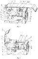
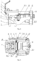
- the capsule coffee machine of the present disclosure comprises a brewing seat 9 and a brewing assembly 10, which are connected with each other by four guiding shafts 13 and can move with respect to each other through the action of a driving assembly.
- the brewing assembly 10 is provided with a making cavity 10.1 for accommodating a coffee capsule 12, and the making cavity 10.1 is provided with a resilient member 15 used for popping up the brewed coffee capsule 12.
- the brewing seat 9 is provided with a hot water channel and a one-way valve used for brewing the coffee capsule 12.
- the capsule coffee machine of the present disclosure further comprises two rotating members 11 located on the two sides of the brewing assembly 10 respectively and two detent members 14 connected with the two rotating members 11 respectively.
- the coffee capsule 12 is provided with a flange
- the detent member 14, which is C-shaped, is provided with a holding groove 14.1 used for holding the flange of the coffee capsule 12.
- each of the two rotating members 11 is connected with the brewing assembly 10 in a rotatable manner.
- the rotating member 11 is connected with the brewing assembly 10 in a rotatable manner means that each of the two sides of the upper end of said brewing assembly 10 is provided with a fixing block 16 respectively, each said fixing block 16 being connected with a first pin 17, with which said rotating member 11 is connected in a rotatable manner.
- the first pin 17 follows the brewing assembly 10 and moves apart from the brewing seat 9, and each detent member 14 is rotated inwardly when a corresponding rotating member 11 rotates about the first pin 17 inwardly.
- the first pin 17 follows the brewing assembly 10 and moves towards the brewing seat 9, and each detent member 14 is rotated outwardly when a corresponding rotating member 11 rotates about the first pin 17 outwardly.
- the first pin 17 follows the brewing assembly 10 and moves apart from the brewing seat 9 again, and each detent member 14 is rotated inwardly to its original position when a corresponding rotating member 11 rotates about the first pin 17 inwardly.
- said rotating member 11 is hinged to the brewing assembly 10.
- the two detent members 14 are hinged to the two sides of the brewing seat 9 respectively, and one end of each detent member 14 is connected with a waist-shaped hole 11.1, which is provided on one end of a corresponding rotating member 11 and used for limiting the detent member 14 in a moveable manner.
- the waist-shaped hole 11.1 is a through hole and the cross section thereof is formed by two arcs at the two ends and two straight lines connecting the two arcs.
- the end of said detent member 14 is provided with a slipping shaft 14.2 cooperating with the waist-shaped hole 11.1.
- the movements of the two slipping shafts 14.2 and the waist-shaped holes 11.1 comprise two kinds of movements, i.e., each slipping shaft 14.2 rotates in the corresponding waist-shaped hole 11.1, and each slipping shaft 14.2 slips back and forth in the corresponding waist-shaped hole 11.1.
- the slipping shaft 14.2 can not only cooperate with the waist-shaped hole 11.1 and convey the rotating force of the rotating member 11 to the detent member 14, so that the detent member 14 can be rotated by the rotating member 11, but also move from one end to another end in the waist-shaped hole 11.1.
- Fig. 5 is a structural diagram of the capsule coffee machine when the brewing assembly 10 starts to move towards the brewing seat 9 after the coffee capsule 12 is placed therein.
- the detent members 14, with the coffee capsule 12 held therebetween, are rotated outwardly by the rotating members 11, and each slipping shaft 14.2 of the detent member 14 is located at one end of the corresponding waist-shaped hole 11.1 far from the brewing assembly 10.
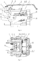
- Fig. 7 is a structural diagram of the capsule coffee machine when the coffee capsule 12 is brewed therein after the brewing assembly 10 has moved close to the brewing seat 9.
- each detent member 14 is further rotated outwardly to a certain location by the corresponding rotating member 11 connected with the brewing assembly 10.
- the coffee capsule 12 is separated from the two detent members 14, and is put into the brewing assembly 10 to brew coffee.
- the brewing assembly 10 continues to move towards the brewing seat 9, and the resilient member 15 in the making cavity 10.1 is compressed gradually.
- the coffee capsule 12 touches the brewing seat 9, the coffee capsule 12 is brewed by the joint action of the brewing seat 9 and the brewing assembly 10.
- each slipping shaft 14.2 of the detent member 14 has moved to the other end of the corresponding waist-shaped hole 11.1 near to the brewing assembly 10 from the end of the corresponding waist-shaped hole 11.1 far from the brewing assembly 10.
- Fig. 9 is a structural diagram of the capsule coffee machine when the brewing assembly 10 is moving apart from the brewing seat 9 after the coffee capsule 12 is brewed.
- the resilient member 15 in the making cavity 10.1 restores gradually, and the brewed coffee capsule 12 is popped up by the action of the resilient force.
- the brewing assembly 10 continues to move apart from the brewing seat 9, so that the interval therebetween becomes larger gradually.
- the interval between the brewing assembly 10 and the brewing seat 9 reaches its maximum value, the detent members 14 are rotated inwardly by the rotating members 11 to their original positions, and thus ready for next brewing.
- said driving assembly comprises: a handle 1.
- One end of said handle 1 is a free end, and a middle part of the other end is connected with a hinge block 2, which is connected with the brewing seat 9 through a first shaft 3.
- the other end of said handle 1 is connected with one end of a first connecting rod 5 through a second shaft 4, the other end of said first connecting rod 5 is connected with one end of each of the two second connecting rods 7 arranged at each of the two sides of the brewing seat 9 respectively through a third shaft 6, and the other end of each of the two second connecting rods 7 is connected with the brewing assembly 10.
- each second connecting rod 7 is connected with the third shaft 6 though a connecting block 8, one end of said connecting block 8 is connected with the third shaft 6 in a rotatable manner, and the other end of said connecting block 8 is hinged to the second connecting rod 7.
- said brewing seat 9 is provided with two limit blocks 18 for limiting said two detent members 14 respectively.
- Each of said limit blocks 18 is connected with a second pin 20, which is sheathed with a middle part of said detent member 14 that is connected with the second pin 20 in a rotatable manner.
- each limit block 18 is mainly used for limiting the inward and outward rotating angle of the corresponding detent member 14.
- said second pin 20 is sheathed with a torsion spring 19 for resetting the detent member 14.
- a torsion spring 19 is connected with the limit block 18, and the other end of said torsion spring 19 is connected with the detent member 14.
- the coffee capsule 12 once being held therein by the cooperation of the two detent members 14, cannot deflect or drop easily, and the detent members 14 can be rotated to their original positions more easily and more quickly.
- each detent member 14 rotates inwardly about the second pin 20 to the detent location and is limited by the inner side of the corresponding limit block 18.
- each detent member 14 rotates outwardly about the second pin 20 to compress the torsion spring 19, and is limited by the outer side of the corresponding limit block 18.
- each detent member 14 rotates inwardly about the second pin 20 to its original position and is limited by the inner side of the corresponding limit block 18 by the action of the restoring force of the corresponding torsion spring 19 and rotating member 11.
- the working principle of the capsule coffee machine of the present disclosure is as follows. First, the handle 1 is lifted, and the driving assembly enables that the brewing assembly 10 moves apart from the brewing seat 9, so that the capsule coffee machine is opened. Second, the coffee capsule 12 is put into the holding grooves 14.1 of the two detent members 14 of the brewing seat 9 from the above, and the coffee capsule 12 is held therein. Then, the handle 1 is pressed, and the brewing assembly 10 moves towards the brewing seat 9 until the interval therebetween disappears. When the brewing assembly 10 is moving towards the brewing seat 9, the two detent members 14 are rotated outwardly by the rotating members 11.
- the coffee capsule 12 is released when the rotating members 11 rotate outwardly to a certain angle, and then moved into the making cavity 10.1 of the brewing assembly 10.
- the resilient member 15 in the making cavity 10.1 is compressed, until the brewing assembly 10 touches the brewing seat 9, i.e., the gap therebetween is closed.
- each detent member 14 rotates outwardly to the largest angle and is limited by the corresponding limit block 18, and each slipping shaft 14.2 moves to one end of the corresponding waist-shaped hole 11.1 near to the brewing assembly 10.
- the resilient member 15 in the brewing assembly 10 restores gradually, and the coffee capsule 12, with only a capsule left therein after brewing, is popped up from the making cavity 10.1 by the action of the resilience.
- the coffee capsule 12 drops automatically from the capsule coffee machine through the interval between the brewing seat 9 and the brewing assembly 10 by the action of the gravity of itself, as shown in Fig. 8 and Fig. 9 .
- the capsule coffee machine of the present disclosure is easy and convenient to operate, and can be used for brewing the coffee capsule 12 of different shapes.
Landscapes
- Engineering & Computer Science (AREA)
- Food Science & Technology (AREA)
- Mechanical Engineering (AREA)
- Apparatus For Making Beverages (AREA)
Claims (11)
- Une cafetière à capsules, comprenant une place de brassage (9) et un assemblage de brassage (10) qui sont mobiles l'un par rapport à l'autre, la cafetière comprenant par ailleurs :deux éléments rotatifs (11) disposés des deux côtes de l'assemblage de brassage (10) respectivement, une extrémité de chaque élément rotatif (11) étant connectée à l'assemblage de brassage (10) par rotation ; etdeux éléments à cran (14) articulés des deux côtés de la place de brassage (9) respectivement, une extrémité de chaque élément à cran (14) étant connectée avec une structure de limitation fournie à l'autre extrémité de l'élément rotatif correspondant (11) situé sur le même côté par rotation ;lorsque l'assemblage de brassage (10) et la place de brassage (9) s'écartent l'un de l'autre, chaque élément à cran (14) est tourné vers l'intérieur par un élément rotatif correspondant (11) situé sur le même côté respectivement, pour que la capsule de café (12) puisse être tenue entre les deux éléments à cran (14) ;lorsque l'assemblage de brassage (10) et la place de brassage (9) se rapprochent l'un de l'autre, chaque élément à cran (14) est tourné vers l'extérieur par l'élément rotatif correspondant (11) pour libérer la capsule de café (12), pour que la capsule de café (12) entre dans une cavité de fabrication de l'assemblage de brassage (10) pour brasser le café ; etlorsque l'assemblage de brassage (10) et la place de brassage (9) s'écartent de nouveau l'un de l'autre, la capsule de café (12) ayant été brassée tombera d'un intervalle entre la place de brassage (9) et l'assemblage de brassage (10) alors que l'intervalle augmente, et chaque élément à cran (14) est tourné vers l'intérieur par l'élément rotatif correspondant (11) à sa position d'origine,caractérisée en ce que la structure de limitation dudit élément rotatif (11) est un trou en forme de ceinture (11.1), et l'extrémité dudit élément à cran (14) étant fournie avec un axe de glissement (14.2) qui peut bouger dans le trou en forme de ceinture (11.1).
- La cafetière à capsules selon la revendication 1, dans laquelle la cavité de fabrication (10.1) de l'assemblage de brassage (10) est incluse avec un élément élastique (15) utilisé pour libérer la capsule de café (12).
- La cafetière à capsules selon la revendication 2, dans laquelle ledit élément élastique (15) est configuré pour être comprimé lorsque l'assemblage de brassage (10) et la place de brassage (9) se rapprochent l'un de l'autre, et pour libérer la capsule de café (12) par une force de rappel lorsque l'assemblage de brassage (10) et la place de brassage (9) s'écartent de nouveau l'un de l'autre.
- La cafetière à capsules selon les revendications de 1 à 3, dans laquelle un mouvement d'ouverture-fermeture relatif entre l'assemblage de brassage (10) et la place de brassage (9) est actionné par un assemblage d'actionnement, qui comprend une poignée (1) ;
dans laquelle une extrémité de ladite poignée (1) est une extrémité libre, et une partie centrale de l'autre extrémité est connectée avec un bloc à charnière (2), qui est connecté avec la place de brassage (9) par un premier arbre (3) ; et dans laquelle l'autre extrémité de ladite poignée (1) est connectée avec une extrémité d'une première bielle (5) par un deuxième arbre (4), l'autre extrémité de ladite première bielle (5) est connectée avec une extrémité de chacune des deux bielles (7) disposées sur chacun des deux côtés de la place de brassage (9) respectivement par un troisième arbre (6) et l'autre extrémité de chacune des deux bielles (7) est connectée avec l'assemblage de brassage (10). - La cafetière à capsules selon la revendication 4, dans laquelle chacune desdites deuxièmes bielles (7) est connectée avec un troisième arbre (6) par un bloc de connexion (8), une extrémité dudit bloc de connexion (8) étant connecté avec le troisième arbre (6) par rotation, et l'autre extrémité dudit bloc de connexion (8) étant articulée sur la deuxième bielle (7).
- La cafetière à capsules selon les revendications de 1 à 5, dans laquelle ledit élément à cran (14) est en forme de C, et est fourni avec une rainure de support (14.1) utilisée pour tenir la capsule de café (12).
- La cafetière à capsules selon les revendications de 1 à 6, dans laquelle chacun des deux côtés de l'extrémité supérieure dudit assemblage de brassage (10) est fourni avec un bloc de fixation (16) respectivement, chaque bloc de fixation (16) étant connecté avec une première broche (17), avec lequel ledit élément rotatif (11) est connecté par rotation.
- La cafetière à capsules selon la revendication 7, dans laquelle lorsque l'assemblage de brassage (10) et la place de brassage (9) s'écartent l'un de l'autre, la première broche (17) suit l'assemblage de brassage (10) et s'écarte de la place de brassage (9), et chaque élément à cran (14) est tourné vers l'intérieur lorsqu'un élément rotatif (11) tourne vers l'intérieur autour de la première broche (17) ;
lorsque l'assemblage de brassage (10) et la place de brassage (9) se rapprochent l'un de l'autre, la première broche (17) suit l'assemblage de brassage (10) et se rapproche de la place de brassage (9), et chaque élément à cran (14) est tourné vers l'extérieur lorsque l'élément rotatif correspondant (11) tourne autour de la première broche (17) ; et
lorsque l'assemblage de brassage (10) et la place de brassage (9) s'écartent de nouveau l'un de l'autre, la première broche (17) suit l'assemblage de brassage (10) et s'écarte de nouveau de la place de brassage (9), et chaque élément à cran (14) est tourné vers l'intérieur à sa position d'origine lorsqu'un élément rotatif correspondant (11) tourne vers l'intérieur autour de la première broche (17). - La cafetière à capsules selon les revendications 1 à 8, dans laquelle ladite place de brassage (9) est fournie avec deux blocs de limitation (18) pour limiter lesdits deux éléments à cran (14) respectivement, chacun desdits blocs de limitation (18) étant connecté avec une deuxième broche (20), qui est recouverte avec une partie centrale dudit élément à cran (14) qui est connecté avec la deuxième broche (20) par rotation.
- La cafetière à capsules selon la revendication 9, dans laquelle ladite deuxième broche (20) est recouverte avec un ressort de torsion (19) pour reconfigurer l'élément à cran (14), une extrémité dudit ressort de torsion (19) étant connecté avec le bloc de limitation (18), et l'autre extrémité dudit ressort de torsion (19) étant connecté avec l'élément à cran (14).
- La cafetière à capsules selon la revendication 10,
dans laquelle ledit assemblage de brassage (10) et la place de brassage (9) s'écartent l'un de l'autre, chaque élément à cran (14) tourne vers l'intérieur autour de la deuxième broche (20) vers l'emplacement du cran et est donc limité par le côté intérieur du bloc de limitation correspondant (18) ;
lorsque l'assemblage de brassage (10) et la place de brassage (9) se rapprochent l'un de l'autre, chaque élément à cran (14) tourne vers l'extérieur autour de la deuxième broche (20), pour que le ressort de torsion (19) soit comprimé, et chaque élément à cran (14) soit limité par le côté extérieur du bloc de limitation correspondant (18) ; et
lorsque l'assemblage de brassage (10) et la place de brassage (9) s'écartent de nouveau l'un de l'autre, chaque élément à cran (14) tourne vers l'intérieur autour de la deuxième broche (20) à sa position d'origine et est limité par le côté intérieur du bloc de limitation correspondant (18) par l'action de la force de rappel du ressort de torsion correspondant (19) et l'élément rotatif (11).
Applications Claiming Priority (3)
| Application Number | Priority Date | Filing Date | Title |
|---|---|---|---|
| CN201210306470.1A CN102813458B (zh) | 2012-08-24 | 2012-08-24 | 胶囊咖啡机的自动掉胶囊装置 |
| CN201220426214.1U CN202891617U (zh) | 2012-08-24 | 2012-08-24 | 胶囊咖啡机的自动掉胶囊装置 |
| PCT/CN2013/080506 WO2014029264A1 (fr) | 2012-08-24 | 2013-07-31 | Machine à café en capsules |
Publications (3)
| Publication Number | Publication Date |
|---|---|
| EP2888977A1 EP2888977A1 (fr) | 2015-07-01 |
| EP2888977A4 EP2888977A4 (fr) | 2016-05-11 |
| EP2888977B1 true EP2888977B1 (fr) | 2018-03-28 |
Family
ID=50149411
Family Applications (1)
| Application Number | Title | Priority Date | Filing Date |
|---|---|---|---|
| EP13831272.3A Active EP2888977B1 (fr) | 2012-08-24 | 2013-07-31 | Machine à café à capsules |
Country Status (3)
| Country | Link |
|---|---|
| US (1) | US9730546B2 (fr) |
| EP (1) | EP2888977B1 (fr) |
| WO (1) | WO2014029264A1 (fr) |
Families Citing this family (6)
| Publication number | Priority date | Publication date | Assignee | Title |
|---|---|---|---|---|
| US10045654B2 (en) | 2014-02-14 | 2018-08-14 | Coffee Solutions, Llc | Moving inlet nozzles in beverage systems |
| DE102015121029B4 (de) * | 2015-12-03 | 2018-10-31 | Eugster/Frismag Ag | Getränkezubereitungsvorrichtung, System sowie Betriebsverfahren |
| CN106580092A (zh) * | 2016-11-18 | 2017-04-26 | 浙江酷菲尔电器有限公司 | 一种自动酿造装置的传动机构 |
| US11627828B2 (en) | 2017-07-10 | 2023-04-18 | Guangdong Midea Consumer Electric Manufacturing Co., Ltd. | Locking brewing device, beverage brewing device and beverage machine |
| CN110811330B (zh) * | 2018-08-07 | 2024-07-02 | 广东亿龙电器科技有限公司 | 直立式胶囊咖啡机及其胶囊咖啡酿造结构 |
| CN110279301B (zh) * | 2019-07-29 | 2024-08-27 | 东莞市优尼雅电子科技有限公司 | 胶囊咖啡机的泄压装置及胶囊咖啡机 |
Family Cites Families (20)
| Publication number | Priority date | Publication date | Assignee | Title |
|---|---|---|---|---|
| CH664886A5 (fr) * | 1985-04-30 | 1988-04-15 | Nestle Sa | Appareil pour la confection automatique d'une boisson. |
| US5657683A (en) * | 1993-06-07 | 1997-08-19 | Sandei; Pietro | Hot beverage brewing apparatus |
| US6459854B1 (en) * | 2000-01-24 | 2002-10-01 | Nestec S.A. | Process and module for heating liquid |
| DK1219217T3 (da) * | 2000-12-29 | 2004-01-05 | Sgl Italia Srl | Kaffemaskine |
| EP1495702A1 (fr) * | 2003-07-10 | 2005-01-12 | Nestec S.A. | Dispositif pour l'extraction d'une capsule |
| NL1026834C2 (nl) * | 2004-08-12 | 2006-02-14 | Sara Lee De Nv | Bereiden van thee met behulp van een theepad en een koffiezetapparaat. |
| KR20100071697A (ko) * | 2008-12-19 | 2010-06-29 | 주식회사 텐텐투 | 캡슐을 이용한 음료추출장치 |
| CN101703363B (zh) | 2009-11-10 | 2012-01-18 | 广东新宝电器股份有限公司 | 自动掉胶囊咖啡机 |
| DK2368466T3 (en) * | 2010-03-24 | 2014-03-03 | Delica Ag | A device for preparing a beverage |
| CN201734530U (zh) | 2010-05-19 | 2011-02-09 | 广东新宝电器股份有限公司 | 全自动胶囊咖啡机 |
| CN202015065U (zh) | 2010-08-11 | 2011-10-26 | 漳州灿坤实业有限公司 | 一种咖啡机 |
| CN201822642U (zh) | 2010-09-20 | 2011-05-11 | 宁波贝仕迪电器有限公司 | 一种胶囊式咖啡机 |
| CN102068204B (zh) * | 2010-12-13 | 2013-03-27 | 宁波三A集团电器有限公司 | 一种方便脱包的饮料萃取装置 |
| EP2543290A1 (fr) * | 2011-07-08 | 2013-01-09 | Koninklijke Philips Electronics N.V. | Unité de brassage dotée d'un chauffage pour l'eau |
| ITVR20110180A1 (it) * | 2011-09-19 | 2013-03-20 | Caffita System Spa | Dispositivo di infusione per la produzione di bevande mediante l'utilizzo di cartucce, quali capsule o cialde |
| EP2599412A1 (fr) * | 2011-12-01 | 2013-06-05 | Nestec S.A. | Machine de préparation de boissons |
| CN202891617U (zh) | 2012-08-24 | 2013-04-24 | 广东新宝电器股份有限公司 | 胶囊咖啡机的自动掉胶囊装置 |
| CN102813458B (zh) * | 2012-08-24 | 2014-12-17 | 广东新宝电器股份有限公司 | 胶囊咖啡机的自动掉胶囊装置 |
| CN103271652B (zh) * | 2013-06-18 | 2015-08-05 | 宁波西文电器有限公司 | 咖啡机的机件驱动结构 |
| ITTO20130589A1 (it) * | 2013-07-12 | 2015-01-13 | Lavazza Luigi Spa | Sistema per la preparazione di bevande |
-
2013
- 2013-07-31 US US14/423,567 patent/US9730546B2/en active Active
- 2013-07-31 WO PCT/CN2013/080506 patent/WO2014029264A1/fr not_active Ceased
- 2013-07-31 EP EP13831272.3A patent/EP2888977B1/fr active Active
Non-Patent Citations (1)
| Title |
|---|
| None * |
Also Published As
| Publication number | Publication date |
|---|---|
| US9730546B2 (en) | 2017-08-15 |
| EP2888977A4 (fr) | 2016-05-11 |
| WO2014029264A1 (fr) | 2014-02-27 |
| US20150216349A1 (en) | 2015-08-06 |
| EP2888977A1 (fr) | 2015-07-01 |
Similar Documents
| Publication | Publication Date | Title |
|---|---|---|
| EP2888977B1 (fr) | Machine à café à capsules | |
| EP3715569B1 (fr) | Charnière hydraulique cachée positionnable | |
| US20060005353A1 (en) | Hinge device and electronic device using hinge device | |
| CN109311144A (zh) | 工具头 | |
| EP2907946B1 (fr) | Verrou de libération de pression | |
| EP2767188B1 (fr) | Charnière réglable et canapé | |
| EP2881341A1 (fr) | Couvercle de boîte à ordures doté d'un mécanisme de compression à ordures et poubelle comprenant celui-ci | |
| CN104389473A (zh) | 家具铰链缓冲装置的稳固装配结构 | |
| US20210351806A1 (en) | Tablet computer case | |
| US9256257B2 (en) | Electronic device and docking station | |
| CN215568352U (zh) | 一种防止误操作的阀杆 | |
| CN112041523A (zh) | 提升把手布置 | |
| US8161988B2 (en) | Central shaft control structure of self-opening/closing umbrella | |
| EP2336689A2 (fr) | Poignée de porte pour appareil de réfrigération domestique | |
| EP2732734B1 (fr) | Appareil de cuisson d'aliments sous pression à commande de déverrouillage améliorée | |
| JP2013231284A (ja) | ヒンジ構造 | |
| JP3544949B2 (ja) | ヒンジ装置並びにヒンジ装置を用いた携帯式電子機器 | |
| KR200338810Y1 (ko) | 자동 개방형 화장품 콤팩트 | |
| KR20050027322A (ko) | 자동 개방형 화장품 콤팩트 | |
| CN202891638U (zh) | 一种弹开盖结构 | |
| CN110748237B (zh) | 一种门锁把手防猫眼开启机构及具有其的门锁 | |
| CN219083196U (zh) | 油烟机 | |
| JP4003925B2 (ja) | 容器の蝶番構造 | |
| JP2005240901A (ja) | セパレートプッシュオープンヒンジ装置 | |
| JP5215259B2 (ja) | 引戸用指挟み防止具 |
Legal Events
| Date | Code | Title | Description |
|---|---|---|---|
| PUAI | Public reference made under article 153(3) epc to a published international application that has entered the european phase |
Free format text: ORIGINAL CODE: 0009012 |
|
| 17P | Request for examination filed |
Effective date: 20150217 |
|
| AK | Designated contracting states |
Kind code of ref document: A1 Designated state(s): AL AT BE BG CH CY CZ DE DK EE ES FI FR GB GR HR HU IE IS IT LI LT LU LV MC MK MT NL NO PL PT RO RS SE SI SK SM TR |
|
| AX | Request for extension of the european patent |
Extension state: BA ME |
|
| RIN1 | Information on inventor provided before grant (corrected) |
Inventor name: LIN, JINRU Inventor name: GUO, JIANGANG Inventor name: LIU, YU |
|
| DAX | Request for extension of the european patent (deleted) | ||
| RA4 | Supplementary search report drawn up and despatched (corrected) |
Effective date: 20160412 |
|
| RIC1 | Information provided on ipc code assigned before grant |
Ipc: A47J 31/18 20060101AFI20160406BHEP |
|
| GRAP | Despatch of communication of intention to grant a patent |
Free format text: ORIGINAL CODE: EPIDOSNIGR1 |
|
| STAA | Information on the status of an ep patent application or granted ep patent |
Free format text: STATUS: GRANT OF PATENT IS INTENDED |
|
| INTG | Intention to grant announced |
Effective date: 20170321 |
|
| GRAJ | Information related to disapproval of communication of intention to grant by the applicant or resumption of examination proceedings by the epo deleted |
Free format text: ORIGINAL CODE: EPIDOSDIGR1 |
|
| GRAL | Information related to payment of fee for publishing/printing deleted |
Free format text: ORIGINAL CODE: EPIDOSDIGR3 |
|
| GRAS | Grant fee paid |
Free format text: ORIGINAL CODE: EPIDOSNIGR3 |
|
| STAA | Information on the status of an ep patent application or granted ep patent |
Free format text: STATUS: REQUEST FOR EXAMINATION WAS MADE |
|
| INTC | Intention to grant announced (deleted) | ||
| GRAR | Information related to intention to grant a patent recorded |
Free format text: ORIGINAL CODE: EPIDOSNIGR71 |
|
| STAA | Information on the status of an ep patent application or granted ep patent |
Free format text: STATUS: GRANT OF PATENT IS INTENDED |
|
| GRAJ | Information related to disapproval of communication of intention to grant by the applicant or resumption of examination proceedings by the epo deleted |
Free format text: ORIGINAL CODE: EPIDOSDIGR1 |
|
| GRAR | Information related to intention to grant a patent recorded |
Free format text: ORIGINAL CODE: EPIDOSNIGR71 |
|
| GRAJ | Information related to disapproval of communication of intention to grant by the applicant or resumption of examination proceedings by the epo deleted |
Free format text: ORIGINAL CODE: EPIDOSDIGR1 |
|
| GRAR | Information related to intention to grant a patent recorded |
Free format text: ORIGINAL CODE: EPIDOSNIGR71 |
|
| GRAJ | Information related to disapproval of communication of intention to grant by the applicant or resumption of examination proceedings by the epo deleted |
Free format text: ORIGINAL CODE: EPIDOSDIGR1 |
|
| INTG | Intention to grant announced |
Effective date: 20170919 |
|
| STAA | Information on the status of an ep patent application or granted ep patent |
Free format text: STATUS: REQUEST FOR EXAMINATION WAS MADE |
|
| INTG | Intention to grant announced |
Effective date: 20170922 |
|
| INTC | Intention to grant announced (deleted) | ||
| GRAR | Information related to intention to grant a patent recorded |
Free format text: ORIGINAL CODE: EPIDOSNIGR71 |
|
| STAA | Information on the status of an ep patent application or granted ep patent |
Free format text: STATUS: GRANT OF PATENT IS INTENDED |
|
| GRAA | (expected) grant |
Free format text: ORIGINAL CODE: 0009210 |
|
| STAA | Information on the status of an ep patent application or granted ep patent |
Free format text: STATUS: THE PATENT HAS BEEN GRANTED |
|
| INTG | Intention to grant announced |
Effective date: 20180206 |
|
| AK | Designated contracting states |
Kind code of ref document: B1 Designated state(s): AL AT BE BG CH CY CZ DE DK EE ES FI FR GB GR HR HU IE IS IT LI LT LU LV MC MK MT NL NO PL PT RO RS SE SI SK SM TR |
|
| REG | Reference to a national code |
Ref country code: GB Ref legal event code: FG4D |
|
| REG | Reference to a national code |
Ref country code: CH Ref legal event code: EP |
|
| REG | Reference to a national code |
Ref country code: AT Ref legal event code: REF Ref document number: 982603 Country of ref document: AT Kind code of ref document: T Effective date: 20180415 |
|
| REG | Reference to a national code |
Ref country code: IE Ref legal event code: FG4D |
|
| REG | Reference to a national code |
Ref country code: DE Ref legal event code: R096 Ref document number: 602013035193 Country of ref document: DE |
|
| REG | Reference to a national code |
Ref country code: FR Ref legal event code: PLFP Year of fee payment: 6 |
|
| PG25 | Lapsed in a contracting state [announced via postgrant information from national office to epo] |
Ref country code: LT Free format text: LAPSE BECAUSE OF FAILURE TO SUBMIT A TRANSLATION OF THE DESCRIPTION OR TO PAY THE FEE WITHIN THE PRESCRIBED TIME-LIMIT Effective date: 20180328 Ref country code: HR Free format text: LAPSE BECAUSE OF FAILURE TO SUBMIT A TRANSLATION OF THE DESCRIPTION OR TO PAY THE FEE WITHIN THE PRESCRIBED TIME-LIMIT Effective date: 20180328 Ref country code: NO Free format text: LAPSE BECAUSE OF FAILURE TO SUBMIT A TRANSLATION OF THE DESCRIPTION OR TO PAY THE FEE WITHIN THE PRESCRIBED TIME-LIMIT Effective date: 20180628 Ref country code: FI Free format text: LAPSE BECAUSE OF FAILURE TO SUBMIT A TRANSLATION OF THE DESCRIPTION OR TO PAY THE FEE WITHIN THE PRESCRIBED TIME-LIMIT Effective date: 20180328 |
|
| REG | Reference to a national code |
Ref country code: NL Ref legal event code: MP Effective date: 20180328 |
|
| REG | Reference to a national code |
Ref country code: LT Ref legal event code: MG4D |
|
| PG25 | Lapsed in a contracting state [announced via postgrant information from national office to epo] |
Ref country code: GR Free format text: LAPSE BECAUSE OF FAILURE TO SUBMIT A TRANSLATION OF THE DESCRIPTION OR TO PAY THE FEE WITHIN THE PRESCRIBED TIME-LIMIT Effective date: 20180629 Ref country code: LV Free format text: LAPSE BECAUSE OF FAILURE TO SUBMIT A TRANSLATION OF THE DESCRIPTION OR TO PAY THE FEE WITHIN THE PRESCRIBED TIME-LIMIT Effective date: 20180328 Ref country code: SE Free format text: LAPSE BECAUSE OF FAILURE TO SUBMIT A TRANSLATION OF THE DESCRIPTION OR TO PAY THE FEE WITHIN THE PRESCRIBED TIME-LIMIT Effective date: 20180328 Ref country code: RS Free format text: LAPSE BECAUSE OF FAILURE TO SUBMIT A TRANSLATION OF THE DESCRIPTION OR TO PAY THE FEE WITHIN THE PRESCRIBED TIME-LIMIT Effective date: 20180328 Ref country code: BG Free format text: LAPSE BECAUSE OF FAILURE TO SUBMIT A TRANSLATION OF THE DESCRIPTION OR TO PAY THE FEE WITHIN THE PRESCRIBED TIME-LIMIT Effective date: 20180628 |
|
| PG25 | Lapsed in a contracting state [announced via postgrant information from national office to epo] |
Ref country code: EE Free format text: LAPSE BECAUSE OF FAILURE TO SUBMIT A TRANSLATION OF THE DESCRIPTION OR TO PAY THE FEE WITHIN THE PRESCRIBED TIME-LIMIT Effective date: 20180328 Ref country code: PL Free format text: LAPSE BECAUSE OF FAILURE TO SUBMIT A TRANSLATION OF THE DESCRIPTION OR TO PAY THE FEE WITHIN THE PRESCRIBED TIME-LIMIT Effective date: 20180328 Ref country code: AL Free format text: LAPSE BECAUSE OF FAILURE TO SUBMIT A TRANSLATION OF THE DESCRIPTION OR TO PAY THE FEE WITHIN THE PRESCRIBED TIME-LIMIT Effective date: 20180328 Ref country code: ES Free format text: LAPSE BECAUSE OF FAILURE TO SUBMIT A TRANSLATION OF THE DESCRIPTION OR TO PAY THE FEE WITHIN THE PRESCRIBED TIME-LIMIT Effective date: 20180328 Ref country code: RO Free format text: LAPSE BECAUSE OF FAILURE TO SUBMIT A TRANSLATION OF THE DESCRIPTION OR TO PAY THE FEE WITHIN THE PRESCRIBED TIME-LIMIT Effective date: 20180328 Ref country code: NL Free format text: LAPSE BECAUSE OF FAILURE TO SUBMIT A TRANSLATION OF THE DESCRIPTION OR TO PAY THE FEE WITHIN THE PRESCRIBED TIME-LIMIT Effective date: 20180328 |
|
| PG25 | Lapsed in a contracting state [announced via postgrant information from national office to epo] |
Ref country code: CZ Free format text: LAPSE BECAUSE OF FAILURE TO SUBMIT A TRANSLATION OF THE DESCRIPTION OR TO PAY THE FEE WITHIN THE PRESCRIBED TIME-LIMIT Effective date: 20180328 Ref country code: SM Free format text: LAPSE BECAUSE OF FAILURE TO SUBMIT A TRANSLATION OF THE DESCRIPTION OR TO PAY THE FEE WITHIN THE PRESCRIBED TIME-LIMIT Effective date: 20180328 Ref country code: SK Free format text: LAPSE BECAUSE OF FAILURE TO SUBMIT A TRANSLATION OF THE DESCRIPTION OR TO PAY THE FEE WITHIN THE PRESCRIBED TIME-LIMIT Effective date: 20180328 |
|
| REG | Reference to a national code |
Ref country code: AT Ref legal event code: MK05 Ref document number: 982603 Country of ref document: AT Kind code of ref document: T Effective date: 20180328 |
|
| PG25 | Lapsed in a contracting state [announced via postgrant information from national office to epo] |
Ref country code: PT Free format text: LAPSE BECAUSE OF FAILURE TO SUBMIT A TRANSLATION OF THE DESCRIPTION OR TO PAY THE FEE WITHIN THE PRESCRIBED TIME-LIMIT Effective date: 20180730 |
|
| REG | Reference to a national code |
Ref country code: DE Ref legal event code: R097 Ref document number: 602013035193 Country of ref document: DE |
|
| PG25 | Lapsed in a contracting state [announced via postgrant information from national office to epo] |
Ref country code: AT Free format text: LAPSE BECAUSE OF FAILURE TO SUBMIT A TRANSLATION OF THE DESCRIPTION OR TO PAY THE FEE WITHIN THE PRESCRIBED TIME-LIMIT Effective date: 20180328 Ref country code: DK Free format text: LAPSE BECAUSE OF FAILURE TO SUBMIT A TRANSLATION OF THE DESCRIPTION OR TO PAY THE FEE WITHIN THE PRESCRIBED TIME-LIMIT Effective date: 20180328 |
|
| PLBE | No opposition filed within time limit |
Free format text: ORIGINAL CODE: 0009261 |
|
| STAA | Information on the status of an ep patent application or granted ep patent |
Free format text: STATUS: NO OPPOSITION FILED WITHIN TIME LIMIT |
|
| REG | Reference to a national code |
Ref country code: CH Ref legal event code: PL |
|
| 26N | No opposition filed |
Effective date: 20190103 |
|
| GBPC | Gb: european patent ceased through non-payment of renewal fee |
Effective date: 20180731 |
|
| PG25 | Lapsed in a contracting state [announced via postgrant information from national office to epo] |
Ref country code: LU Free format text: LAPSE BECAUSE OF NON-PAYMENT OF DUE FEES Effective date: 20180731 Ref country code: MC Free format text: LAPSE BECAUSE OF FAILURE TO SUBMIT A TRANSLATION OF THE DESCRIPTION OR TO PAY THE FEE WITHIN THE PRESCRIBED TIME-LIMIT Effective date: 20180328 |
|
| REG | Reference to a national code |
Ref country code: BE Ref legal event code: MM Effective date: 20180731 |
|
| PG25 | Lapsed in a contracting state [announced via postgrant information from national office to epo] |
Ref country code: CH Free format text: LAPSE BECAUSE OF NON-PAYMENT OF DUE FEES Effective date: 20180731 Ref country code: LI Free format text: LAPSE BECAUSE OF NON-PAYMENT OF DUE FEES Effective date: 20180731 Ref country code: GB Free format text: LAPSE BECAUSE OF NON-PAYMENT OF DUE FEES Effective date: 20180731 |
|
| REG | Reference to a national code |
Ref country code: IE Ref legal event code: MM4A |
|
| PG25 | Lapsed in a contracting state [announced via postgrant information from national office to epo] |
Ref country code: SI Free format text: LAPSE BECAUSE OF FAILURE TO SUBMIT A TRANSLATION OF THE DESCRIPTION OR TO PAY THE FEE WITHIN THE PRESCRIBED TIME-LIMIT Effective date: 20180328 Ref country code: BE Free format text: LAPSE BECAUSE OF NON-PAYMENT OF DUE FEES Effective date: 20180731 |
|
| PG25 | Lapsed in a contracting state [announced via postgrant information from national office to epo] |
Ref country code: IE Free format text: LAPSE BECAUSE OF NON-PAYMENT OF DUE FEES Effective date: 20180731 |
|
| PG25 | Lapsed in a contracting state [announced via postgrant information from national office to epo] |
Ref country code: MT Free format text: LAPSE BECAUSE OF NON-PAYMENT OF DUE FEES Effective date: 20180731 |
|
| PG25 | Lapsed in a contracting state [announced via postgrant information from national office to epo] |
Ref country code: TR Free format text: LAPSE BECAUSE OF FAILURE TO SUBMIT A TRANSLATION OF THE DESCRIPTION OR TO PAY THE FEE WITHIN THE PRESCRIBED TIME-LIMIT Effective date: 20180328 |
|
| PG25 | Lapsed in a contracting state [announced via postgrant information from national office to epo] |
Ref country code: CY Free format text: LAPSE BECAUSE OF FAILURE TO SUBMIT A TRANSLATION OF THE DESCRIPTION OR TO PAY THE FEE WITHIN THE PRESCRIBED TIME-LIMIT Effective date: 20180328 Ref country code: MK Free format text: LAPSE BECAUSE OF NON-PAYMENT OF DUE FEES Effective date: 20180328 Ref country code: HU Free format text: LAPSE BECAUSE OF FAILURE TO SUBMIT A TRANSLATION OF THE DESCRIPTION OR TO PAY THE FEE WITHIN THE PRESCRIBED TIME-LIMIT; INVALID AB INITIO Effective date: 20130731 |
|
| PG25 | Lapsed in a contracting state [announced via postgrant information from national office to epo] |
Ref country code: IS Free format text: LAPSE BECAUSE OF FAILURE TO SUBMIT A TRANSLATION OF THE DESCRIPTION OR TO PAY THE FEE WITHIN THE PRESCRIBED TIME-LIMIT Effective date: 20180728 |
|
| REG | Reference to a national code |
Ref country code: DE Ref legal event code: R082 Ref document number: 602013035193 Country of ref document: DE Representative=s name: HL KEMPNER PATENTANWAELTE, SOLICITORS (ENGLAND, DE Ref country code: DE Ref legal event code: R082 Ref document number: 602013035193 Country of ref document: DE Representative=s name: HL KEMPNER PATENTANWALT, RECHTSANWALT, SOLICIT, DE Ref country code: DE Ref legal event code: R082 Ref document number: 602013035193 Country of ref document: DE Representative=s name: HL KEMPNER PARTG MBB, DE |
|
| PGFP | Annual fee paid to national office [announced via postgrant information from national office to epo] |
Ref country code: DE Payment date: 20250730 Year of fee payment: 13 |
|
| PGFP | Annual fee paid to national office [announced via postgrant information from national office to epo] |
Ref country code: IT Payment date: 20250730 Year of fee payment: 13 |
|
| PGFP | Annual fee paid to national office [announced via postgrant information from national office to epo] |
Ref country code: FR Payment date: 20250730 Year of fee payment: 13 |