EP2888986B1 - Pumpe zum Abführen einer Flüssigkeit und Haushaltsgerät mit einer solchen Pumpe - Google Patents
Pumpe zum Abführen einer Flüssigkeit und Haushaltsgerät mit einer solchen Pumpe Download PDFInfo
- Publication number
- EP2888986B1 EP2888986B1 EP14199828.6A EP14199828A EP2888986B1 EP 2888986 B1 EP2888986 B1 EP 2888986B1 EP 14199828 A EP14199828 A EP 14199828A EP 2888986 B1 EP2888986 B1 EP 2888986B1
- Authority
- EP
- European Patent Office
- Prior art keywords
- pump
- impeller
- discharging
- end cap
- liquid according
- Prior art date
- Legal status (The legal status is an assumption and is not a legal conclusion. Google has not performed a legal analysis and makes no representation as to the accuracy of the status listed.)
- Active
Links
Images



Classifications
-
- F—MECHANICAL ENGINEERING; LIGHTING; HEATING; WEAPONS; BLASTING
- F04—POSITIVE - DISPLACEMENT MACHINES FOR LIQUIDS; PUMPS FOR LIQUIDS OR ELASTIC FLUIDS
- F04D—NON-POSITIVE-DISPLACEMENT PUMPS
- F04D13/00—Pumping installations or systems
- F04D13/02—Units comprising pumps and their driving means
- F04D13/06—Units comprising pumps and their driving means the pump being electrically driven
- F04D13/0606—Canned motor pumps
- F04D13/0613—Special connection between the rotor compartments
-
- F—MECHANICAL ENGINEERING; LIGHTING; HEATING; WEAPONS; BLASTING
- F04—POSITIVE - DISPLACEMENT MACHINES FOR LIQUIDS; PUMPS FOR LIQUIDS OR ELASTIC FLUIDS
- F04D—NON-POSITIVE-DISPLACEMENT PUMPS
- F04D13/00—Pumping installations or systems
- F04D13/02—Units comprising pumps and their driving means
- F04D13/06—Units comprising pumps and their driving means the pump being electrically driven
-
- A—HUMAN NECESSITIES
- A47—FURNITURE; DOMESTIC ARTICLES OR APPLIANCES; COFFEE MILLS; SPICE MILLS; SUCTION CLEANERS IN GENERAL
- A47L—DOMESTIC WASHING OR CLEANING; SUCTION CLEANERS IN GENERAL
- A47L15/00—Washing or rinsing machines for crockery or tableware
- A47L15/42—Details
- A47L15/4214—Water supply, recirculation or discharge arrangements; Devices therefor
- A47L15/4225—Arrangements or adaption of recirculation or discharge pumps
-
- F—MECHANICAL ENGINEERING; LIGHTING; HEATING; WEAPONS; BLASTING
- F04—POSITIVE - DISPLACEMENT MACHINES FOR LIQUIDS; PUMPS FOR LIQUIDS OR ELASTIC FLUIDS
- F04D—NON-POSITIVE-DISPLACEMENT PUMPS
- F04D29/00—Details, component parts, or accessories
- F04D29/04—Shafts or bearings, or assemblies thereof
- F04D29/042—Axially shiftable rotors
-
- F—MECHANICAL ENGINEERING; LIGHTING; HEATING; WEAPONS; BLASTING
- F04—POSITIVE - DISPLACEMENT MACHINES FOR LIQUIDS; PUMPS FOR LIQUIDS OR ELASTIC FLUIDS
- F04D—NON-POSITIVE-DISPLACEMENT PUMPS
- F04D29/00—Details, component parts, or accessories
- F04D29/08—Sealings
- F04D29/086—Sealings especially adapted for liquid pumps
-
- F—MECHANICAL ENGINEERING; LIGHTING; HEATING; WEAPONS; BLASTING
- F04—POSITIVE - DISPLACEMENT MACHINES FOR LIQUIDS; PUMPS FOR LIQUIDS OR ELASTIC FLUIDS
- F04D—NON-POSITIVE-DISPLACEMENT PUMPS
- F04D29/00—Details, component parts, or accessories
- F04D29/08—Sealings
- F04D29/16—Sealings between pressure and suction sides
- F04D29/165—Sealings between pressure and suction sides especially adapted for liquid pumps
- F04D29/167—Sealings between pressure and suction sides especially adapted for liquid pumps of a centrifugal flow wheel
-
- F—MECHANICAL ENGINEERING; LIGHTING; HEATING; WEAPONS; BLASTING
- F04—POSITIVE - DISPLACEMENT MACHINES FOR LIQUIDS; PUMPS FOR LIQUIDS OR ELASTIC FLUIDS
- F04D—NON-POSITIVE-DISPLACEMENT PUMPS
- F04D29/00—Details, component parts, or accessories
- F04D29/18—Rotors
- F04D29/22—Rotors specially for centrifugal pumps
-
- F—MECHANICAL ENGINEERING; LIGHTING; HEATING; WEAPONS; BLASTING
- F04—POSITIVE - DISPLACEMENT MACHINES FOR LIQUIDS; PUMPS FOR LIQUIDS OR ELASTIC FLUIDS
- F04D—NON-POSITIVE-DISPLACEMENT PUMPS
- F04D7/00—Pumps adapted for handling specific fluids, e.g. by selection of specific materials for pumps or pump parts
- F04D7/02—Pumps adapted for handling specific fluids, e.g. by selection of specific materials for pumps or pump parts of centrifugal type
- F04D7/04—Pumps adapted for handling specific fluids, e.g. by selection of specific materials for pumps or pump parts of centrifugal type the fluids being viscous or non-homogenous
Definitions
- the present invention relates to a pump for discharging a liquid, in particular a drainage pump.
- the present invention also relates to a household appliance with such a pump, in particular a dishwasher or a washing machine.
- the impeller When the pump is in operation, the impeller is rotated for liquid discharge at a high speed in the hydraulic chamber, with the hair, particles, fibers or the like contained in the liquid. With the rotary movement of the impeller enter the game and become on the rotating shaft or around the The rotating shaft may accumulate or twist, preventing high-speed operational rotation of the rotating shaft and affecting drainage performance of the pump.
- the DE 69 05 217 U describes a centrifugal pump for washing machines and dishwashers, the pump housing surrounding the pump rotor is composed of at least two parts, the pump rotor having an annular web which protrudes into an annular groove.
- JP H 10274195 A an annular groove is formed on an impeller between a seal housing and an annular wall of the impeller.
- the object of the present invention is to provide a structurally improved pump for discharging a liquid, with which the operational discharge capacity of a liquid discharge pump can be ensured.
- a pump for discharging a liquid with an engine compartment an electric motor, which has a drive shaft and is located in the engine compartment, and an impeller which is attached to the drive shaft, wherein between a front end cap of the engine compartment and the Impeller there is an axial play. It is provided that an annular groove is formed in the front end cap of the engine compartment and an annular impeller extension extending in the direction of the annular groove is formed on the impeller and the impeller is attached to the drive shaft in such a way that when the impeller is pushed onto the drive shaft, there is axial play between the impeller and the front end cap of the engine compartment.
- the impeller moves axially back and forth with the drive shaft at a high speed rotation, with the annular groove in the front end cap creating a larger space for the axial reciprocating movement of the impeller, in order to ensure contact between the annular impeller extension and the front Avoid end cap.
- annular impeller extension and the ring groove coordinated with it, it is achieved during a high-speed rotation of the impeller in the liquid when the pump is operating to discharge a liquid that the hairs, particles, fibers or the like contained in the liquid are difficult to deal with Rotary movement of the impeller can get into the axial play between the front end cap of the engine compartment and the impeller through a channel formed by the annular impeller extension and the ring groove that is matched to it. In this way, it is possible to prevent such foreign matter from accumulating or winding on the drive shaft or around the drive shaft, thereby preventing high-speed operational rotation of the drive shaft and impairing the discharge performance of the pump.
- the impeller moves axially back and forth with the drive shaft at the same time as the high-speed rotation, the annular groove in the front end cap being able to create a larger space for the axial reciprocating movement of the impeller, in order to ensure contact between the annular impeller extension and front end cap.
- both the annular impeller extension of the impeller and the annular groove coordinated therewith can be provided in a number of more than one. If there is sufficient space available on the impeller and the front end cap, one or more additional annular impeller extensions and within the annular groove also one or more additional, correspondingly arranged annular grooves can be provided within the annular impeller extension of the impeller, with the annular impeller extensions each protrude axially into an associated annular groove.
- the annular impeller extension protrudes axially into the annular groove.
- annular impeller extension and the ring groove adapted to it, which is even more difficult for hair, particles, fibers or the like contained in the liquid to pass.
- a slight shortening of the drive shaft is conceivable in order to somewhat reduce the overall axial length of the pump for discharging a liquid.
- the axial play has an axial width that is at least greater than 1.5 mm.
- the axial width of the axial play is between 1.5 mm and 3.5 mm.
- the annular impeller extension extends axially in the direction of the front end cap of the engine compartment by a predetermined amount.
- the annular groove is formed in a surface of the front end cap of the engine compartment.
- annular end cap extension which is arranged around the annular groove and extends axially by a predetermined amount is additionally formed on the front end cap of the engine compartment.
- the radial play, the annular groove and the axial play are connected to one another while forming a curved channel.
- the curved channel comprises at least a first and a second corner.
- both the first and the second corner have an angle of approximately 90 degrees.
- the curved channel first extends axially in a direction pointing towards the front end cap to the first corner and then in the longitudinal direction to the second corner. This in turn is followed by an axial extension in a direction pointing away from the front end cap.
- the result is an even more curvaceous curved canal, which makes it even more difficult that the in discharged liquid containing hair, particles, fibers or the like. Enter through this channel in the axial play between the front end cap of the engine compartment and impeller and accumulate or wind on the drive shaft or around the drive shaft.
- annular grooves can be formed in the front end cap and correspondingly several annular impeller projections can be formed on the impeller, so that the curved channel has a longer course and more similar first and second corners.
- the annular groove has a greater radial width than the annular impeller extension.
- the annular groove has a radial width which is 1-4 mm larger than the radial width of the annular impeller extension.
- annular impeller extension protrudes into the annular groove, so that the above-described curved channel is created. Moreover, when the impeller rotates at high speed, the annular impeller extension can rotate freely in the annular groove.
- the annular impeller extension has an axial length that is greater than the axial width of the axial play.
- the annular impeller extension has an axial length which is 1.5-4 mm greater than the axial width of the axial play.
- the annular impeller extension can axially exceed the axial play in order to protrude into the annular groove and thereby generate the curved channel described above.
- the impeller is attached to the drive shaft in such a way that when the impeller is pushed onto the drive shaft, the axial play is created between the impeller and the front end cap of the engine compartment.
- the impeller, the annular impeller extension and the annular groove are arranged concentrically to one another.
- the pump for discharging a liquid is a centrifugal pump for discharging water.
- the invention further proposes a household appliance operated with water, in particular a dishwasher or a washing machine, which comprises a pump for discharging a liquid according to one of the preceding configurations.
- the dishwasher GS shown comprises an interior IR serving as a washing container, which can be opened or closed by a door (not designated), wherein the door is pivotably connected to the dishwasher GS for the purpose of loading or unloading.
- a crockery basket GK for receiving an object to be cleaned is arranged in the interior IR of the dishwasher GS and can be removed from the interior IR of the dishwasher GS in order to simplify loading and unloading.
- a spray device in the form of a spray arm SA for applying a fluid to the object to be cleaned is installed in the interior IR of the dishwasher GS, the fluid being e.g. water mixed with a cleaning or rinsing agent can act to enable cleaning and / or spotless drying of the object to be cleaned.
- the fluid dripping down from the object to be cleaned is collected in a pump sump PS, which is located in a floor area of the interior IR of the dishwasher GS.
- a filter device (not designated) is also built into the pump sump PS, with which impurities or particles can be separated from the circulating fluid.
- the spray arm SA is flow-connected via a supply line ZL to a circulating pump UP, which is located in the vicinity of the other dishwasher components of a bottom part BO arranged below the interior IR of the dishwasher GS.
- a circulating pump UP When the circulating pump UP is operating, the fluid collected in the pump sump PS is sucked in by the circulating pump UP and fed to the spray arm SA via the supply line ZL.
- the circulation pump UP comprises an integrated water heater WZ in order to heat the fluid flowing through the circulation pump UP.
- separate continuous heating or other water heating systems can also be provided in order to heat the fluid.
- a pump for discharging a liquid LP in particular for discharging a liquid located in the interior IR of the dishwasher GS, is provided in the dishwasher GS, which pump can be flow-connected both to the pump sump PS and to a drainage line EL of a household sewage drainage network.
- the pump comprises for discharging a liquid LP, in particular for discharging a liquid located in the interior IR of the dishwasher Liquid, an engine room 10 in which an electric motor 20 is installed.
- the electric motor 20 comprises a rotor chamber 14 located in the engine compartment 10, in which a drive shaft 40 provided with a bearing 70 and a rotor 50 is installed.
- a stator 60 is arranged around the rotor chamber 14.
- An impeller 30 is attached to one end of the rotary shaft 40 protruding from the engine room 10. When the electric motor 20 is operated, the impeller 30 is rotated at high speed by the rotary shaft 40 in order to discharge the liquid.
- annular groove 12 is formed in a surface of a front end cap 11 of the engine compartment 10, and an annular end cap extension 13 is formed around it and extends axially by a predetermined amount. Furthermore, the impeller 30 is attached to the rotary shaft 40 in an area of the rotary shaft 40 facing the front end cap 11, an annular impeller extension 31 formed on the impeller 30 extending in the direction of the annular groove 12 in the front end cap 11, preferably into the Annular groove 12 extends.
- the annular groove 12 has a radial width which is preferably 1-4 mm larger than the radial width of the annular impeller extension 31. Furthermore, the impeller 30, the annular impeller extension 31 and the annular groove 12 are arranged concentrically to one another.
- the impeller 30 is attached to the rotary shaft 40 in the area of the rotary shaft 40 facing the front end cap 11 such that there is an axial play L1 between the impeller 30 and the front end cap 11, see in this regard FIG 4 .
- This axial play L1 has an axial width which is at least greater than 1.5 mm and is preferably between 1.5 mm and 3.5 mm.
- the annular impeller extension 31 has an axial length which is preferably 1.5-4 mm greater than the axial width of the axial play L1, and can therefore axially exceed the axial play L1 in order to project into the annular groove 12.
- the curved channel 80 first extends axially in a direction pointing towards the front end cap 11 up to a first corner and then in the longitudinal direction up to a second corner. This is initially followed by an axial extension in a direction pointing away from the front end cap 11 and then again by a longitudinal extension. This results in a longer and more curvilinear curved channel 80, the first and second corners preferably each having an angle of approximately 90 degrees.
- annular impeller extension 31 and the annular groove 12 adapted to it, during a high-speed rotation of the impeller 30 in the liquid when the pump is operating to discharge a liquid, the hair, particles, fibers or the like contained in the liquid are only Difficult to get into the axial play L1 between the front end cap 11 of the engine compartment 10 and the impeller 30 with the rotary movement of the impeller 30 through the curved channel 80 formed by the annular impeller extension 31 and the matching annular groove 12. In this way, such foreign matter can be prevented from accumulating or winding on the drive shaft 40 or around the drive shaft, thereby preventing high-speed operational rotation of the drive shaft 40 and impairing the discharge performance of the pump.
- the impeller 30 moves axially back and forth simultaneously with the high speed rotation with the drive shaft 40, the annular groove 12 in the front end cap 11 creating a larger space for the axial reciprocation of the impeller 30 to contact between To avoid annular impeller extension 31 and front end cap 11 and an associated prevention of high-speed rotation.
- both the annular impeller extension 31 of the impeller 30 and the annular groove 12 coordinated therewith can be provided in a number greater than one. So, if there is sufficient space available on the impeller 31 and the front end cap 11, one or more additional annular impeller extensions within the annular impeller extension 31 of the impeller 30 and one or more additional, appropriately arranged ones within the annular groove 12 Annular grooves may be provided, the annular impeller extensions each projecting axially into an associated annular groove.
Landscapes
- Engineering & Computer Science (AREA)
- Mechanical Engineering (AREA)
- General Engineering & Computer Science (AREA)
- Water Supply & Treatment (AREA)
- Structures Of Non-Positive Displacement Pumps (AREA)
Description
- Die vorliegende Erfindung betrifft eine Pumpe zum Abführen einer Flüssigkeit, insbesondere eine Entwässerungspumpe.
- Die vorliegende Erfindung betrifft ferner ein Haushaltsgerät mit einer solchen Pumpe, insbesondere ein Geschirrspüler oder eine Waschmaschine.
- Bei den bestehenden, in herkömmlicher Weise aufgebauten Pumpen zum Abführen einer Flüssigkeit führt die Antriebswelle zusammen mit dem Rotor des Elektromotors in der Rotorkammer eine Drehbewegung durch, während sich das Flügelrad der Pumpe in der Hydraulikkammer dreht. Näheres hierzu findet sich in der europäischen Patentanmeldung
EP 2455614 A2 . Die aus der Pumpe abgeführte Flüssigkeit, wie beispielsweise das Waschwasser eines Geschirrspülers oder einer Waschmaschine, ist oft mit Haaren, Partikeln, Fasern oder dgl. beschmutzt. Zudem ist zwischen dem an der Antriebswelle angebrachten Flügelrad und einer vorderen Endkappe des Motorraums ein gewisses Spiel vorhanden, um eine freie Drehung des Flügelrades zu gewährleisten. Beim Betrieb der Pumpe wird das Flügelrad zur Flüssigkeitsabführung mit einer hohen Geschwindigkeit in der Hydraulikkammer gedreht, wobei die in der Flüssigkeit enthaltenen Haare, Partikel, Fasern oder dgl. mit der Drehbewegung des Flügelrades in das genannte Spiel eintreten und sich an der Drehwelle oder um die Drehwelle ansammeln oder winden, wodurch eine betriebsmäßige Hochgeschwindigkeitsdrehung der Drehwelle verhindert und die Entwässerungsleistung der Pumpe beeinträchtigt wird. - Die
DE 69 05 217 U beschreibt eine Zentrifugalpumpe für Wasch- und Geschirrspülmaschinen, deren den Pumpenrotor umgebendes Pumpengehäuse aus mindestens zwei Teilen zusammengesetzt ist, wobei der Pumpenrotor einen Ringsteg aufweist, der in eine kreisringförmige Rille hineinragt. - In
DE 10 2009 028 310 A1 ist der dortige Lagerbolzen feststehend im topfförmigen Gehäuse fixiert und dreht sich demgemäß nicht. - In
JP H 10274195 A - In der
WO 2012/123978 A2 dient der dortige ringförmige Vorsprung des Flügelrades und die ringförmige Nut (es Zylinders als ein Axiallager, um den vertikal stehenden Rotor in dem Zylinder zu führen. - In der
EP 0 487 785 A1 wird eine Kupplung beschrieben, die ein Verdrehspiel aufweist. - In der
US 4,955,793 sitzt das Flügelrad fest auf der Antriebswelle. Die Antriebswelle ist mittels eines vorderen Rillenkugellagers und eines hinteren Rillenkugellagers im Gehäuse gelagert. Diese beiden Rillenkugellager sind auf der Antriebswelle in einer angestellten Lagerung verspannt. - Aufgabe der vorliegenden Erfindung ist es, eine strukturell verbesserte Pumpe zum Abführen einer Flüssigkeit bereitzustellen, mit der die betriebsmäßige Ablassleistung einer Flüssigkeitsabführpumpe gewährleistet werden kann.
- Erfindungsgemäß wird die Aufgabe gelöst durch eine Pumpe zum Abführen einer Flüssigkeit mit einem Motorraum, einem Elektromotor, der eine Antriebswelle aufweist und sich in dem Motorraum befindet, und einem Flügelrad, das an der Antriebswelle angebracht ist, wobei zwischen einer vorderen Endkappe des Motorraums und dem Flügelrad ein axiales Spiel vorhanden ist. Dabei ist vorgesehen, dass in der vorderen Endkappe des Motorraums eine Ringnut und an dem Flügelrad ein sich in Richtung auf die Ringnut erstreckender, ringförmiger Flügelrad-Fortsatz ausgebildet ist und das Flügelrad an der Antriebswelle so angebracht ist, dass beim Aufschieben des Flügelrades auf die Antriebswelle zwischen Flügelrad und vorderer Endkappe des Motorraums das axiale Spiel entsteht. Ferner bewegt sich das Flügelrad bei einer Hochgeschwindigkeitsdrehung mit der Antriebswelle axial hin und her I, wobei mit der Ringnut in der vorderen Endkappe ein größerer Platz für die axiale Hin- und Herbewegung des Flügelrades geschaffen wird, um einen Kontakt zwischen ringförmigem Flügelrad-Fortsatz und vorderer Endkappe zu vermeiden.
- Durch das Vorsehen des ringförmigen Flügelrad-Fortsatzes und der darauf abgestimmten Ringnut wird während einer Hochgeschwindigkeitsdrehung des Flügelrades in der Flüssigkeit beim Betrieb der Pumpe zum Abführen einer Flüssigkeit erreicht, dass die in der Flüssigkeit enthaltenen Haare, Partikel, Fasern oder dgl. nur schwer mit der Drehbewegung des Flügelrades durch einen durch den ringförmigen Flügelrad-Fortsatz und die darauf abgestimmte Ringnut gebildeten Kanal in das axiale Spiel zwischen vorderer Endkappe des Motorraums und Flügelrad gelangen können. Auf diese Weise kann vermieden werden, dass sich solche Fremdkörper an der Antriebswelle oder um die Antriebswelle ansammeln oder winden, wodurch eine betriebsmäßige Hochgeschwindigkeitsdrehung der Antriebswelle verhindert und die Ablassleistung der Pumpe beeinträchtigt wird.
- Des Weiteren bewegt sich das Flügelrad gleichzeitig bei der Hochgeschwindigkeitsdrehung mit der Antriebswelle axial hin und her, wobei mit der Ringnut in der vorderen Endkappe ein größerer Platz für die axiale Hin- und Herbewegung des Flügelrades geschaffen werden kann, um einen Kontakt zwischen ringförmigem Flügelrad-Fortsatz und vorderer Endkappe zu vermeiden.
- Darüber hinaus können sowohl der ringförmige Flügelrad-Fortsatz des Flügelrades als auch die darauf abgestimmte Ringnut in einer Anzahl von mehr als Eins bereitgestellt werden. So können, sofern an dem Flügelrad und der vorderen Endkappe ausreichender Platz zur Verfügung steht, innerhalb des ringförmigen Flügelrad-Fortsatzes des Flügelrades ein oder mehrere zusätzliche ringförmige Flügelrad-Fortsätze und innerhalb der Ringnut ebenfalls eine oder mehrere zusätzliche, entsprechend angeordnete Ringnuten vorgesehen sein, wobei die ringförmigen Flügelrad-Fortsätze jeweils axial in eine zugeordnete Ringnut hineinragen. Durch das Vorsehen mehrerer ringförmiger Flügelrad-Fortsätze und mehrerer darauf abgestimmter Ringnuten kann ein kurvenreicherer Kanal erzeugt werden, wodurch es noch weiter erschwert wird, dass die in der abgeführten Flüssigkeit enthaltenen Haare, Partikel, Fasern oder dgl. durch diesen Kanal in das axiale Spiel zwischen vorderer Endkappe des Motorraums und Flügelrad eintreten und sich an der Antriebswelle oder um die Antriebswelle ansammeln oder winden.
- In einer Weiterbildung der Erfindung ragt der ringförmige Flügelrad-Fortsatz axial in die Ringnut hinein.
- Auf diese Weise kann durch den ringförmigen Flügelrad-Fortsatz und die darauf abgestimmte Ringnut ein noch kurvenreicherer Kanal gebildet sein, der für in der Flüssigkeit enthaltenen Haare, Partikel, Fasern oder dgl. noch schwerer zu passieren ist. Zugleich ist eine geringfügige Verkürzung der Antriebswelle denkbar, um die axiale Gesamtlänge der Pumpe zum Abführen einer Flüssigkeit etwas zu reduzieren.
- In einer Weiterbildung der Erfindung weist das axiale Spiel eine axiale Breite auf, die mindestens größer als 1,5 mm ist.
- In einer Weiterbildung der Erfindung liegt die axiale Breite des axialen Spiels zwischen 1,5 mm und 3,5 mm.
- In einer Weiterbildung der Erfindung erstreckt sich der ringförmige Flügelrad-Fortsatz axial in Richtung auf die vordere Endkappe des Motorraums um ein vorgegebenes Maß.
- Mit einer derartigen Ausgestaltung können ein axiales Hineinragen des ringförmigen Flügelrad-Fortsatzes in die Ringnut und damit eine Zusammenwirkung zwischen ringförmigem Flügelrad-Fortsatz und Ringnut gewährleistet werden.
- In einer Weiterbildung der Erfindung ist die Ringnut in einer Oberfläche der vorderen Endkappe des Motorraums ausgebildet.
- In einer Weiterbildung der Erfindung ist an der vorderen Endkappe des Motorraums zusätzlich ein um die Ringnut herum angeordneter, ringförmiger Endkappenfortsatz ausgebildet, der sich axial um ein vorgegebenes Maß erstreckt.
- In einer Weiterbildung der Erfindung ist zwischen ringförmigem Endkappenfortsatz und ringförmigem Flügelrad-Fortsatz ein radiales Spiel vorhanden.
- In einer Weiterbildung der Erfindung sind das radiale Spiel, die Ringnut und das axiale Spiel unter Ausbildung eines gebogenen Kanals miteinander verbunden.
- Daraus resultiert ein längerer Zugangskanal, wodurch es noch weiter erschwert wird, dass die in der abgeführten Flüssigkeit enthaltenen Haare, Partikel, Fasern oder dgl. durch diesen Kanal in das axiale Spiel zwischen vorderer Endkappe des Motorraums und Flügelrad eintreten und sich an der Antriebswelle oder um die Antriebswelle ansammeln oder winden. In diesem Zusammenhang können selbstverständlich, wie oben erwähnt, in der vorderen Endkappe mehrere Ringnuten und an dem Flügelrad entsprechend mehrere ringförmige Flügelrad-Fortsätze ausgebildet sein. Daraus ergibt sich ein noch kurvenreicherer gebogener Kanal, der es noch schwerer macht, dass die in der abgeführten Flüssigkeit enthaltenen Haare, Partikel, Fasern oder dgl. durch diesen Kanal in das axiale Spiel zwischen vorderer Endkappe des Motorraums und Flügelrad eintreten und sich an der Antriebswelle oder um die Antriebswelle ansammeln oder winden.
- In einer Weiterbildung der Erfindung umfasst der gebogene Kanal mindestens eine erste und eine zweite Ecke.
- In einer Weiterbildung der Erfindung haben sowohl die erste als auch die zweite Ecke einen Winkel von annähernd 90 Grad.
- Dabei ist vorgesehen, dass sich der gebogene Kanal zunächst axial in einer auf die vordere Endkappe weisenden Richtung bis zur ersten Ecke und danach in Längsrichtung bis zur zweiten Ecke erstreckt. Daran schließt sich wiederum eine axiale Erstreckung in einer von der vorderen Endkappe wegweisenden Richtung. Daraus resultiert ein noch kurvenreicherer gebogener Kanal, der es noch schwerer macht, dass die in der abgeführten Flüssigkeit enthaltenen Haare, Partikel, Fasern oder dgl. durch diesen Kanal in das axiale Spiel zwischen vorderer Endkappe des Motorraums und Flügelrad eintreten und sich an der Antriebswelle oder um die Antriebswelle ansammeln oder winden.
- In diesem Zusammenhang können, wie oben erwähnt, in der vorderen Endkappe mehrere Ringnuten und an dem Flügelrad entsprechend mehrere ringförmige Flügelrad-Fortsätze ausgebildet sein, so dass der gebogene Kanal einen längeren Verlauf und mehr ähnliche erste und zweite Ecken hat. Daraus ergibt sich ein noch kurvenreicherer gebogener Kanal, der es noch schwerer macht, dass die in der abgeführten Flüssigkeit enthaltenen Haare, Partikel, Fasern oder dgl. durch diesen Kanal in das axiale Spiel zwischen vorderer Endkappe des Motorraums und Flügelrad eintreten und sich an der Antriebswelle oder um die Antriebswelle ansammeln oder winden.
- In einer Weiterbildung der Erfindung hat die Ringnut eine größere radiale Breite als der ringförmige Flügelrad-Fortsatz.
- In einer Weiterbildung der Erfindung besitzt die Ringnut eine radiale Breite, die um 1-4 mm größer als die radiale Breite des ringförmigen Flügelrad-Fortsatzes ist.
- Mit einer derartigen Ausgestaltung kann erreicht werden, dass der ringförmige Flügelrad-Fortsatz in die Ringnut hineinragt, so dass der oben beschriebene gebogene Kanal entsteht. Überdies wird bei der Hochgeschwindigkeitsdrehung des Flügelrades eine freie Drehbewegung des ringförmigen Flügelrad-Fortsatzes in der Ringnut ermöglicht.
- In einer Weiterbildung der Erfindung hat der ringförmige Flügelrad-Fortsatz eine axiale Länge, die größer als die axiale Breite des axialen Spiels ist.
- In einer Weiterbildung der Erfindung hat der ringförmige Flügelrad-Fortsatz eine axiale Länge, die um 1,5-4 mm größer als die axiale Breite des axialen Spiels ist.
- Mit einer derartigen Ausgestaltung kann der ringförmige Flügelrad-Fortsatz axial das axiale Spiel überschreiten, um in die Ringnut hineinzuragen und dadurch den oben beschriebenen gebogenen Kanal zu erzeugen.
- Gemäß der Erfindung ist das Flügelrad an der Antriebswelle so angebracht, dass beim Aufschieben des Flügelrades auf die Antriebswelle zwischen Flügelrad und vorderer Endkappe des Motorraums das axiale Spiel entsteht.
- In einer Weiterbildung der Erfindung sind das Flügelrad, der ringförmige Flügelrad-Fortsatz und die Ringnut konzentrisch zueinander angeordnet.
- In einer Weiterbildung der Erfindung handelt es sich bei der Pumpe zum Abführen einer Flüssigkeit um eine Kreiselpumpe zur Wasserabführung.
- Die Erfindung schlägt weiter ein mit Wasser betriebenes Haushaltsgerät, insbesondere einen Geschirrspüler oder eine Waschmaschine, vor, das eine Pumpe zum Abführen einer Flüssigkeit gemäß einer der vorangehenden Ausgestaltungen umfasst.
- Nachfolgend wird die Erfindung anhand eines am meisten bevorzugten Ausführungsbeispiels, in dem das mit Wasser betriebene Haushaltsgerät als Geschirrspüler ausgeführt ist, näher beschrieben. Dies ist aber nicht damit gleichzusetzen, dass der Schutzumfang der Erfindung nur auf Geschirrspüler beschränkt ist.
- Es zeigen
-
FIG 1 den schematischen Aufbau eines Haushaltsgeschirrspülers gemäß einem am meisten bevorzugten Ausführungsbeispiel der Erfindung, -
FIG 2 den schematischen Aufbau einer erfindungsgemäßen Pumpe zum Abführen einer Flüssigkeit, -
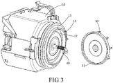
FIG 3 in räumlicher Darstellung den schematischen Aufbau einer erfindungsgemäßen Pumpe zum Abführen einer Flüssigkeit und -
FIG 4 eine herausvergrößerte Ansicht des mit A bezeichneten Bereiches inFIG 2 . - Der in
FIG 1 dargestellte Geschirrspüler GS umfasst einen als Waschbehälter dienenden Innenraum IR, der durch eine Tür (nicht bezeichnet) öffen- bzw. schließbar ist, wobei die Tür zum Zweck der Be- oder Entladung schwenkbar an dem Geschirrspüler GS angeschlossen ist. In dem Innenraum IR des Geschirrspülers GS ist ein Geschirrkorb GK zur Aufnahme eines zu reinigenden Gegenstandes angeordnet, welcher aus dem Innenraum IR des Geschirrspülers GS herausnehmbar ist, um die Be- oder Entladung zu vereinfachen. - Zum Reinigen des in dem Geschirrkorb GK gelagerten, zu reinigenden Gegenstands ist in dem Innenraum IR des Geschirrspülers GS eine Sprüheinrichtung in Form eines Sprüharms SA zum Aufbringen eines Fluids auf den zu reinigenden Gegenstand eingebaut, wobei es sich bei dem Fluid um mit z.B. einem Reinigungs- oder Spülmittel vermengtes Wasser handeln kann, um eine Reinigung und/oder eine fleckenlose Trocknung des zu reinigenden Gegenstands zu ermöglichen. Darüber hinaus wird das von dem zu reinigenden Gegenstand herabtropfende Fluid in einem Pumpensumpf PS gesammelt, der sich in einem Bodenbereich des Innenraums IR des Geschirrspülers GS befindet. In dem Pumpensumpf PS ist ferner eine Filtereinrichtung (nicht bezeichnet) eingebaut, mit der sich Verunreinigungen oder Partikel aus dem zirkulierenden Fluid heraustrennen lassen.
- Weiterhin ist der Sprüharm SA über eine Zuleitung ZL mit einer Umwälzpumpe UP strömungsverbunden, die sich in der Nähe der übrigen Geschirrspüler-Bauteile eines unterhalb des Innenraums IR des Geschirrspülers GS angeordneten Bodenteils BO befindet. Beim Betrieb der Umwälzpumpe UP wird das in dem Pumpensumpf PS gesammelte Fluid durch die Umwälzpumpe UP angesaugt und über die Zuleitung ZL dem Sprüharm SA zugeführt. In diesem beispielhaften Ausführungsbeispiel umfasst die Umwälzpumpe UP eine integrierte Wasserheizung WZ, um das durch die Umwälzpumpe UP strömende Fluid zu erwärmen. Alternativ dazu kann bzw. können auch eine separate Dauerheizung oder anderweitige Wasserheizungen bereitgestellt werden, um das Fluid zu erwärmen. Überdies ist in dem Geschirrspüler GS eine Pumpe zum Abführen einer Flüssigkeit LP, insbesondere zum Abführen einer im Innenraum IR des Geschirrspülers GS befindlichen Flüssigkeit, vorgesehen, die sowohl mit dem Pumpensumpf PS als auch mit einer Entwässerungsleitung EL eines Haushaltsabwasser-Abflussnetzes strömungsverbunden sein kann.
- Wie aus
FIG 2 ersichtlich ist, umfasst die Pumpe zum Abführen einer Flüssigkeit LP, insbesondere zum Abführen einer im Innenraum IR des Geschirrspülers befindlichen Flüssigkeit, einen Motorraum 10, in dem ein Elektromotor 20 eingebaut ist. Der Elektromotor 20 umfasst eine sich in dem Motorraum 10 befindende Rotorkammer 14, in der eine mit einem Lager 70 und einem Rotor 50 versehene Antriebswelle 40 eingebaut ist. Um die Rotorkammer 14 herum ist ein Stator 60 angeordnet. An einem aus dem Motorraum 10 herausragenden Ende der Drehwelle 40 ist ein Flügelrad 30 angebracht. Beim Betrieb des Elektromotors 20 wird das Flügelrad 30 durch die Drehwelle 40 in eine Drehbewegung mit hoher Geschwindigkeit gebracht, um die Flüssigkeit abzuführen. Wie sich ausFIG 3 ergibt, sind in einer Oberfläche einer vorderen Endkappe 11 des Motorraums 10 eine Ringnut 12 und um diese herum ein ringförmiger Endkappenfortsatz 13 ausgebildet, der sich axial um ein vorgegebenes Maß erstreckt. Des Weiteren ist das Flügelrad 30 in einem der vorderen Endkappe 11 zugewandten Bereich der Drehwelle 40 an dieser angebracht, wobei sich ein an dem Flügelrad 30 ausgebildeter, ringförmiger Flügelrad-Fortsatz 31 in Richtung auf die Ringnut 12 in der vorderen Endkappe 11, vorzugsweise in die Ringnut 12, erstreckt. Hierbei besitzt die Ringnut 12 eine radiale Breite, die vorzugsweise um 1-4 mm größer als die radiale Breite des ringförmigen Flügelrad-Fortsatzes 31 ist. Ferner sind das Flügelrad 30, der ringförmige Flügelrad-Fortsatz 31 und die Ringnut 12 konzentrisch zueinander angeordnet. - Zusätzlich dazu ist das Flügelrad 30 in dem der vorderen Endkappe 11 zugewandten Bereich der Drehwelle 40 an dieser so angebracht, dass zwischen Flügelrad 30 und vorderer Endkappe 11 ein axiales Spiel L1 vorhanden ist, siehe hierzu
FIG 4 . Dieses axiale Spiel L1 weist eine axiale Breite auf, die mindestens größer als 1,5 mm ist und bevorzugterweise zwischen 1,5 mm und 3,5 mm liegt. Darüber hinaus hat der ringförmige Flügelrad-Fortsatz 31 eine axiale Länge, die vorzugsweise um 1,5-4 mm größer als die axiale Breite des axialen Spiels L1 ist, und kann daher axial das axiale Spiel L1 überschreiten, um in die Ringnut 12 hineinzuragen. Zudem ist zwischen ringförmigem Flügelrad-Fortsatz 31 und ringförmigem Endkappenfortsatz 13 ein radiales Spiel L2 vorhanden, das unter Ausbildung eines gebogenen Kanals 80 mit der Ringnut 12 und dem axialen Spiel L1 verbunden ist. Dabei ist vorgesehen, dass sich der gebogene Kanal 80 zunächst axial in einer auf die vordere Endkappe 11 weisenden Richtung bis zu einer ersten Ecke und danach in Längsrichtung bis zu einer zweiten Ecke erstreckt. Daran schließen sich zunächst wiederum eine axiale Erstreckung in einer von der vorderen Endkappe 11 wegweisenden Richtung und dann erneut eine Längserstreckung an. Daraus resultiert ein längerer und kurvenreicherer gebogener Kanal 80, wobei die erste und zweite Ecke bevorzugterweise jeweils einen Winkel von annähernd 90 Grad haben. - Durch das Vorsehen des ringförmigen Flügelrad-Fortsatzes 31 und der darauf abgestimmten Ringnut 12 wird während einer Hochgeschwindigkeitsdrehung des Flügelrades 30 in der Flüssigkeit beim Betrieb der Pumpe zum Abführen einer Flüssigkeit erreicht, dass die in der Flüssigkeit enthaltenen Haare, Partikel, Fasern oder dgl. nur schwer mit der Drehbewegung des Flügelrades 30 durch den durch den ringförmigen Flügelrad-Fortsatz 31 und die darauf abgestimmte Ringnut 12 gebildeten, gebogenen Kanal 80 in das axiale Spiel L1 zwischen vorderer Endkappe 11 des Motorraums 10 und Flügelrad 30 gelangen können. Auf diese Weise kann vermieden werden, dass sich solche Fremdkörper an der Antriebswelle 40 oder um die Antriebswelle ansammeln oder winden, wodurch eine betriebsmäßige Hochgeschwindigkeitsdrehung der Antriebswelle 40 verhindert und die Ablassleistung der Pumpe beeinträchtigt wird.
- Des Weiteren bewegt sich das Flügelrad 30 gleichzeitig bei der Hochgeschwindigkeitsdrehung mit der Antriebswelle 40 axial hin und her, wobei mit der Ringnut 12 in der vorderen Endkappe 11 ein größerer Platz für die axiale Hin- und Herbewegung des Flügelrades 30 geschaffen wird, um einen Kontakt zwischen ringförmigem Flügelrad-Fortsatz 31 und vorderer Endkappe 11 und eine damit verbundene Verhinderung der Hochgeschwindigkeitsdrehung zu vermeiden.
- Es versteht sich, dass in einem anderen Ausführungsbeispiel sowohl der ringförmige Flügelrad-Fortsatz 31 des Flügelrades 30 als auch die darauf abgestimmte Ringnut 12 in einer Anzahl von mehr als Eins bereitgestellt werden können. So können, sofern an dem Flügelrad 31 und der vorderen Endkappe 11 ausreichender Platz zur Verfügung steht, innerhalb des ringförmigen Flügelrad-Fortsatzes 31 des Flügelrades 30 ein oder mehrere zusätzliche ringförmige Flügelrad-Fortsätze und innerhalb der Ringnut 12 ebenfalls eine oder mehrere zusätzliche, entsprechend angeordnete Ringnuten vorgesehen sein, wobei die ringförmigen Flügelrad-Fortsätze jeweils axial in eine zugeordnete Ringnut hineinragen. Durch das Vorsehen mehrerer ringförmiger Flügelrad-Fortsätze 31 und mehrerer darauf abgestimmter Ringnuten 12 kann ein noch längerer und kurvenreicherer gebogener Kanal 80 erzeugt werden, wodurch es noch weiter erschwert wird, dass die in der abgeführten Flüssigkeit enthaltenen Haare, Partikel, Fasern oder dgl. durch den gebogenen Kanal 80 in das axiale Spiel L1 zwischen vorderer Endkappe 11 des Motorraums 10 und Flügelrad 30 eintreten und sich an der Antriebswelle 40 oder um die Antriebswelle ansammeln oder winden.
- Das oben Beschriebene stellt keine Einschränkung des Schutzumfangs der Erfindung dar, sondern dient lediglich der näheren Erläuterung möglicher Ausführungsformen der Erfindung. Jede gleichwertige Ausführung oder Variation, welche von den Grundideen der Erfindung ausgeht, ist daher vom Schutzumfang der vorliegenden Erfindung umfasst. Der Schutzumfang wird ausschließlich durch die beigefügten Ansprüche definiert.
-
- 10
- Motorraum
- 11
- Vordere Endkappe
- 12
- Ringnut
- 13
- Ringförmiger Endkappenfortsatz
- 14
- Rotorkammer
- 20
- Elektromotor
- 30
- Flügelrad
- 31
- Ringförmiger Flügelrad-Fortsatz
- 40
- Antriebswelle
- 50
- Rotor
- 60
- Stator
- 70
- Lager
- 80
- Gebogener Kanal
- L1
- Axiales Spiel
- L2
- Radiales Spiel
- GS
- Geschirrspüler
- BO
- Bodenteil
- IR
- Innenraum
- GK
- Geschirrkorb
- SA
- Sprüharm
- PS
- Pumpensumpf
- WZ
- Wasserheizung
- UP
- Umwälzpumpe
- LP
- Pumpe zum Abführen einer Flüssigkeit
- EL
- Entwässerungsleitung
- ZL
- Zuleitung
Claims (19)
- Pumpe zum Abführen einer Flüssigkeit, umfassend- einen Motorraum (10),- einen Elektromotor (20), der eine Antriebswelle (40) aufweist und sich in dem Motorraum (10) befindet,- ein Flügelrad (30), das an der Antriebswelle (40) angebracht ist, wobei zwischen einer vorderen Endkappe (11) des Motorraums (10) und dem Flügelrad (30) ein axiales Spiel (L1) vorhanden ist,wobei in der vorderen Endkappe (11) des Motorraums eine Ringnut (12) und an dem Flügelrad (30) ein sich in Richtung auf die Ringnut (12) erstreckender, ringförmiger Flügelrad-Fortsatz (31) ausgebildet ist, dadurch gekennzeichnet, dass sich das Flügelrad (30) bei einer Hochgeschwindigkeitsdrehung mit der Antriebswelle (40) axial hin und her bewegt, wobei mit der Ringnut (12) in der vorderen Endkappe (11) ein größerer Platz für die axiale Hin- und Herbewegung des Flügelrades (30) geschaffen wird, um einen Kontakt zwischen ringförmigem Flügelrad-Fortsatz (31) und vorderer Endkappe (11) zu vermeiden, und
dass das Flügelrad (31) an der Antriebswelle (40) so angebracht ist, dass beim Aufschieben des Flügelrades (30) auf die Antriebswelle (40) zwischen Flügelrad (30) und vorderer Endkappe (11) des Motorraums das axiale Spiel (L1) entsteht. - Pumpe zum Abführen einer Flüssigkeit gemäß Anspruch 1, dadurch gekennzeichnet, dass der ringförmige Flügelrad-Fortsatz (31) axial in die Ringnut (12) hineinragt.
- Pumpe zum Abführen einer Flüssigkeit gemäß Anspruch 1 oder 2, dadurch gekennzeichnet, dass das axiale Spiel (L1) eine axiale Breite aufweist, die mindestens größer als 1,5 mm ist.
- Pumpe zum Abführen einer Flüssigkeit gemäß Anspruch 3, dadurch gekennzeichnet, dass die axiale Breite des axialen Spiels (L1) zwischen 1,5 mm und 3,5 mm liegt.
- Pumpe zum Abführen einer Flüssigkeit gemäß Anspruch 1 oder 2, dadurch gekennzeichnet, dass sich der ringförmige Flügelrad-Fortsatz (31) axial in Richtung auf die vordere Endkappe (11) des Motorraums um ein vorgegebenes Maß erstreckt.
- Pumpe zum Abführen einer Flüssigkeit gemäß Anspruch 1 oder 2, dadurch gekennzeichnet, dass die Ringnut (12) in einer Oberfläche der vorderen Endkappe (11) des Motorraums ausgebildet ist.
- Pumpe zum Abführen einer Flüssigkeit gemäß Anspruch 1 oder 2, dadurch gekennzeichnet, dass an der vorderen Endkappe (11) des Motorraums zusätzlich ein um die Ringnut (12) herum angeordneter, ringförmiger Endkappenfortsatz (13) ausgebildet, der sich axial um ein vorgegebenes Maß erstreckt.
- Pumpe zum Abführen einer Flüssigkeit gemäß Anspruch 7, dadurch gekennzeichnet, dass zwischen ringförmigem Endkappenfortsatz (13) und ringförmigem Flügelrad-Fortsatz (31) ein radiales Spiel (L2) vorhanden ist.
- Pumpe zum Abführen einer Flüssigkeit gemäß Anspruch 8, dadurch gekennzeichnet, dass das radiale Spiel (L2), die Ringnut (12) und das axiale Spiel (L1) unter Ausbildung eines gebogenen Kanals (80) miteinander verbunden sind.
- Pumpe zum Abführen einer Flüssigkeit gemäß Anspruch 9, dadurch gekennzeichnet, dass der gebogene Kanal (80) mindestens eine erste und eine zweite Ecke umfasst.
- Pumpe zum Abführen einer Flüssigkeit gemäß Anspruch 10, dadurch gekennzeichnet, dass sowohl die erste als auch die zweite Ecke einen Winkel von annähernd 90 Grad haben.
- Pumpe zum Abführen einer Flüssigkeit gemäß Anspruch 1 oder 2, dadurch gekennzeichnet, dass die Ringnut (12) eine größere radiale Breite als der ringförmige Flügelrad-Fortsatz (31) hat.
- Pumpe zum Abführen einer Flüssigkeit gemäß Anspruch 12, dadurch gekennzeichnet, dass die Ringnut (12) eine radiale Breite besitzt, die um 1-4 mm größer als die radiale Breite des ringförmigen Flügelrad-Fortsatzes (31) ist.
- Pumpe zum Abführen einer Flüssigkeit gemäß Anspruch 1 oder 2, dadurch gekennzeichnet, dass der ringförmige Flügelrad-Fortsatz (31) eine axiale Länge hat, die größer als die axiale Breite des axialen Spiels (L1) ist.
- Pumpe zum Abführen einer Flüssigkeit gemäß Anspruch 14, dadurch gekennzeichnet, dass der ringförmige Flügelrad-Fortsatz (31) eine axiale Länge hat, die um 1,5-4 mm größer als die axiale Breite des axialen Spiels (L1) ist.
- Pumpe zum Abführen einer Flüssigkeit gemäß Anspruch 1 oder 2, dadurch gekennzeichnet, dass das Flügelrad (30), der ringförmige Flügelrad-Fortsatz (31) und die Ringnut (12) konzentrisch zueinander angeordnet sind.
- Pumpe zum Abführen einer Flüssigkeit gemäß Anspruch 1 oder 2, dadurch gekennzeichnet, dass es sich bei der Pumpe zum Abführen einer Flüssigkeit (LP) um eine Kreiselpumpe zur Wasserabführung handelt.
- Mit Wasser betriebenes Haushaltsgerät, dadurch gekennzeichnet, dass es eine Pumpe zum Abführen einer Flüssigkeit (LP) gemäß einem der vorangehenden Ansprüche umfasst.
- Mit Wasser betriebenes Haushaltsgerät gemäß Anspruch 18, dadurch gekennzeichnet, dass es ein Geschirrspüler (GS) oder eine Waschmaschine ist.
Priority Applications (1)
| Application Number | Priority Date | Filing Date | Title |
|---|---|---|---|
| PL14199828T PL2888986T3 (pl) | 2013-12-27 | 2014-12-22 | Pompa do odprowadzania płynu i urządzenie gospodarstwa domowego z taką pompą |
Applications Claiming Priority (1)
| Application Number | Priority Date | Filing Date | Title |
|---|---|---|---|
| CN201310740096.0A CN104747458A (zh) | 2013-12-27 | 2013-12-27 | 排放液体的泵及具有该泵的家用电器 |
Publications (2)
| Publication Number | Publication Date |
|---|---|
| EP2888986A1 EP2888986A1 (de) | 2015-07-01 |
| EP2888986B1 true EP2888986B1 (de) | 2020-12-02 |
Family
ID=52231979
Family Applications (1)
| Application Number | Title | Priority Date | Filing Date |
|---|---|---|---|
| EP14199828.6A Active EP2888986B1 (de) | 2013-12-27 | 2014-12-22 | Pumpe zum Abführen einer Flüssigkeit und Haushaltsgerät mit einer solchen Pumpe |
Country Status (4)
| Country | Link |
|---|---|
| EP (1) | EP2888986B1 (de) |
| CN (1) | CN104747458A (de) |
| ES (1) | ES2835252T3 (de) |
| PL (1) | PL2888986T3 (de) |
Families Citing this family (2)
| Publication number | Priority date | Publication date | Assignee | Title |
|---|---|---|---|---|
| US10513928B2 (en) * | 2017-08-31 | 2019-12-24 | Flowserve Management Company | Axial thrust balancing device |
| CN114394170B (zh) * | 2022-03-04 | 2025-02-14 | 珠海市一微机器人技术有限公司 | 一种驱动轮模组及轮式机器人 |
Citations (7)
| Publication number | Priority date | Publication date | Assignee | Title |
|---|---|---|---|---|
| DE6905217U (de) | 1969-02-11 | 1969-11-20 | Licentia Gmbh | Zentrifugalpumpe fuer wasch- oder geschirrspuelmaschinen |
| US4955793A (en) * | 1988-08-17 | 1990-09-11 | Nowax S.R.L. | Turbopump and similar operating machine with sealing connection structure to the motor |
| EP0487785A1 (de) | 1990-11-30 | 1992-06-03 | Siemens Aktiengesellschaft | Pumpenrad-Antrieb |
| JPH10274195A (ja) | 1997-03-31 | 1998-10-13 | Matsushita Electric Ind Co Ltd | ポンプ |
| DE102009028310A1 (de) | 2009-08-06 | 2011-02-10 | Robert Bosch Gmbh | Flüssigkeitspumpe |
| EP2455614A2 (de) | 2010-11-23 | 2012-05-23 | ebm-papst Landshut GmbH | Pumpe zur Förderung von Flüssigkeiten |
| WO2012123978A2 (en) | 2011-03-15 | 2012-09-20 | Hydor Srl | Synchronous electric motor for the operation of a pump and the related motor pump |
Family Cites Families (2)
| Publication number | Priority date | Publication date | Assignee | Title |
|---|---|---|---|---|
| KR970006929A (ko) * | 1995-07-25 | 1997-02-21 | 배순훈 | 냉각수 강제순환방식의 온수순환펌프 |
| CN2485457Y (zh) * | 2001-05-29 | 2002-04-10 | 于国强 | 一种改进的家用电器排水泵用叶轮 |
-
2013
- 2013-12-27 CN CN201310740096.0A patent/CN104747458A/zh active Pending
-
2014
- 2014-12-22 ES ES14199828T patent/ES2835252T3/es active Active
- 2014-12-22 PL PL14199828T patent/PL2888986T3/pl unknown
- 2014-12-22 EP EP14199828.6A patent/EP2888986B1/de active Active
Patent Citations (8)
| Publication number | Priority date | Publication date | Assignee | Title |
|---|---|---|---|---|
| DE6905217U (de) | 1969-02-11 | 1969-11-20 | Licentia Gmbh | Zentrifugalpumpe fuer wasch- oder geschirrspuelmaschinen |
| FR2035233A5 (de) | 1969-02-11 | 1970-12-18 | Licentia Gmbh | |
| US4955793A (en) * | 1988-08-17 | 1990-09-11 | Nowax S.R.L. | Turbopump and similar operating machine with sealing connection structure to the motor |
| EP0487785A1 (de) | 1990-11-30 | 1992-06-03 | Siemens Aktiengesellschaft | Pumpenrad-Antrieb |
| JPH10274195A (ja) | 1997-03-31 | 1998-10-13 | Matsushita Electric Ind Co Ltd | ポンプ |
| DE102009028310A1 (de) | 2009-08-06 | 2011-02-10 | Robert Bosch Gmbh | Flüssigkeitspumpe |
| EP2455614A2 (de) | 2010-11-23 | 2012-05-23 | ebm-papst Landshut GmbH | Pumpe zur Förderung von Flüssigkeiten |
| WO2012123978A2 (en) | 2011-03-15 | 2012-09-20 | Hydor Srl | Synchronous electric motor for the operation of a pump and the related motor pump |
Non-Patent Citations (11)
| Title |
|---|
| ANLAGENKONVOLUT MIT BESTELLUNGEN, LIEFERSCHEINEN UND RECHNUNGEN FÜR DIE ENTLEERUNGSPUMPE DP035-023 |
| ANLAGENKONVOLUT MIT BESTELLUNGEN, LIEFERSCHEINEN UND RECHNUNGEN FÜR DIE ENTLEERUNGSPUMPE DPS25-039 |
| ANLAGENKONVOLUT MIT DEN EINZELTEILZEICHNUNGEN DER ZUR BERECHNUNG DES AXIALEN SPIELS NOTWENDIGEN TEILE FÜR DIE ENTLEERUNGSPUMPE DP035-023 |
| ANLAGENKONVOLUT MIT DEN EINZELTEILZEICHNUNGEN DER ZUR BERECHNUNG DES AXIALEN SPIELS NOTWENDIGEN TEILE FÜR DIE ENTLEERUNGSPUMPE DPS25-039 |
| EIDESSTATTLICHE VERSICHERUNG VON HERRN NORBERT KROGMEIER |
| EIDESSTATTLICHE VERSICHERUNG VON HERRN THOMAS PFLUG |
| EINZELTEILZEICHNUNG FÜR DAS LAUFRAD (FLÜGELRAD) ZUR ENTLEERUNGSPUMPE DP035-023 |
| MONTAGEZEICHNUNG FÜR DIE ENTLEERUNGSPUMPE DP035-023 VOM, 2 August 2006 (2006-08-02) |
| MONTAGEZEICHNUNG FÜR DIE ENTLEERUNGSPUMPE DPS25-039, 6 October 1997 (1997-10-06) |
| STÜCKLISTE FÜR DIE ENTLEERUNGSPUMPE DP035-023, 2 August 2006 (2006-08-02) |
| STÜCKLISTE FÜR DIE ENTLEERUNGSPUMPE DPS25-039, 6 October 1997 (1997-10-06) |
Also Published As
| Publication number | Publication date |
|---|---|
| PL2888986T3 (pl) | 2021-06-14 |
| ES2835252T3 (es) | 2021-06-22 |
| EP2888986A1 (de) | 2015-07-01 |
| CN104747458A (zh) | 2015-07-01 |
Similar Documents
| Publication | Publication Date | Title |
|---|---|---|
| DE102007061038B4 (de) | Wasserführendes Haushaltsgerät | |
| DE102012103419B4 (de) | Rotationsfilter für Geschirrspüler | |
| DE102012102182A1 (de) | Geschirrspüler mit Filteranordnung | |
| DE102012102184A1 (de) | Geschirrspüler mit Filteranordnung | |
| DE102011052846A1 (de) | Geschirrspüler mit gesteuertem Umlauf des unteren Sprüharms | |
| EP2205140B1 (de) | Wasserführendes haushaltsgerät mit selbstreinigendem filter | |
| WO2017162680A1 (de) | Gewerbliches gargerät | |
| EP2656767B1 (de) | Reinigungs- und Desinfektionsautomat | |
| EP2381827B1 (de) | Verfahren zum abpumpen einer flüssigkeit aus einem wasserführenden haushaltsgerät | |
| EP2888986B1 (de) | Pumpe zum Abführen einer Flüssigkeit und Haushaltsgerät mit einer solchen Pumpe | |
| DE102011079887A1 (de) | Wasserführendes Haushaltsgerät mit einer Heizpumpe | |
| WO2018007144A1 (de) | Wäschepflegegerät mit einer steuerung | |
| EP2416694B1 (de) | Wasserführendes haushaltsgerät, insbesondere geschirrspülmaschine | |
| EP3297510B1 (de) | Pumpvorrichtung für ein haushaltsgerät | |
| EP3172371B1 (de) | Haushaltsgerät mit einem umpumpsystem | |
| EP2898811B1 (de) | Flüssigkeitsabführpumpe und Haushaltsgerät mit einer solchen Pumpe | |
| EP3443156B1 (de) | Wäschepflegegerät mit einer steuerung | |
| EP1913262B1 (de) | Pumpengehäuse, pumpe und wasserführendes haushaltsgerät | |
| WO2010124960A1 (de) | Geschirrspülmaschine und umwälzpumpe mit wasserweiche | |
| DE102013215585B4 (de) | Großküchenkessel mit Waschsystem | |
| EP3473156B1 (de) | Geschirrspülmaschine | |
| EP3414461B1 (de) | Wäschepflegegerät mit einer laugenpumpe | |
| DE102015216580B3 (de) | Haushaltsgerät mit einer Pumpvorrichtung | |
| EP4129147B1 (de) | Einspülsystem für waschmittel | |
| DE102016201975B3 (de) | Wäschepflegegerät mit einer Pumpe |
Legal Events
| Date | Code | Title | Description |
|---|---|---|---|
| PUAI | Public reference made under article 153(3) epc to a published international application that has entered the european phase |
Free format text: ORIGINAL CODE: 0009012 |
|
| 17P | Request for examination filed |
Effective date: 20141222 |
|
| AK | Designated contracting states |
Kind code of ref document: A1 Designated state(s): AL AT BE BG CH CY CZ DE DK EE ES FI FR GB GR HR HU IE IS IT LI LT LU LV MC MK MT NL NO PL PT RO RS SE SI SK SM TR |
|
| AX | Request for extension of the european patent |
Extension state: BA ME |
|
| RIN1 | Information on inventor provided before grant (corrected) |
Inventor name: EISERT, HORST Inventor name: LI, ZHENGWEI |
|
| R17P | Request for examination filed (corrected) |
Effective date: 20160104 |
|
| RBV | Designated contracting states (corrected) |
Designated state(s): AL AT BE BG CH CY CZ DE DK EE ES FI FR GB GR HR HU IE IS IT LI LT LU LV MC MK MT NL NO PL PT RO RS SE SI SK SM TR |
|
| 17Q | First examination report despatched |
Effective date: 20160906 |
|
| STAA | Information on the status of an ep patent application or granted ep patent |
Free format text: STATUS: EXAMINATION IS IN PROGRESS |
|
| REG | Reference to a national code |
Ref country code: DE Ref legal event code: R079 Ref document number: 502014015062 Country of ref document: DE Free format text: PREVIOUS MAIN CLASS: A47L0015420000 Ipc: F04D0013060000 |
|
| GRAP | Despatch of communication of intention to grant a patent |
Free format text: ORIGINAL CODE: EPIDOSNIGR1 |
|
| STAA | Information on the status of an ep patent application or granted ep patent |
Free format text: STATUS: GRANT OF PATENT IS INTENDED |
|
| RIC1 | Information provided on ipc code assigned before grant |
Ipc: F04D 7/04 20060101ALI20200622BHEP Ipc: F04D 29/042 20060101ALI20200622BHEP Ipc: A47L 15/42 20060101ALI20200622BHEP Ipc: F04D 13/06 20060101AFI20200622BHEP Ipc: F04D 29/16 20060101ALI20200622BHEP |
|
| INTG | Intention to grant announced |
Effective date: 20200717 |
|
| GRAS | Grant fee paid |
Free format text: ORIGINAL CODE: EPIDOSNIGR3 |
|
| GRAA | (expected) grant |
Free format text: ORIGINAL CODE: 0009210 |
|
| STAA | Information on the status of an ep patent application or granted ep patent |
Free format text: STATUS: THE PATENT HAS BEEN GRANTED |
|
| AK | Designated contracting states |
Kind code of ref document: B1 Designated state(s): AL AT BE BG CH CY CZ DE DK EE ES FI FR GB GR HR HU IE IS IT LI LT LU LV MC MK MT NL NO PL PT RO RS SE SI SK SM TR |
|
| REG | Reference to a national code |
Ref country code: GB Ref legal event code: FG4D Free format text: NOT ENGLISH |
|
| REG | Reference to a national code |
Ref country code: AT Ref legal event code: REF Ref document number: 1341226 Country of ref document: AT Kind code of ref document: T Effective date: 20201215 Ref country code: CH Ref legal event code: EP |
|
| REG | Reference to a national code |
Ref country code: DE Ref legal event code: R096 Ref document number: 502014015062 Country of ref document: DE |
|
| REG | Reference to a national code |
Ref country code: IE Ref legal event code: FG4D Free format text: LANGUAGE OF EP DOCUMENT: GERMAN |
|
| PG25 | Lapsed in a contracting state [announced via postgrant information from national office to epo] |
Ref country code: GR Free format text: LAPSE BECAUSE OF FAILURE TO SUBMIT A TRANSLATION OF THE DESCRIPTION OR TO PAY THE FEE WITHIN THE PRESCRIBED TIME-LIMIT Effective date: 20210303 Ref country code: FI Free format text: LAPSE BECAUSE OF FAILURE TO SUBMIT A TRANSLATION OF THE DESCRIPTION OR TO PAY THE FEE WITHIN THE PRESCRIBED TIME-LIMIT Effective date: 20201202 Ref country code: RS Free format text: LAPSE BECAUSE OF FAILURE TO SUBMIT A TRANSLATION OF THE DESCRIPTION OR TO PAY THE FEE WITHIN THE PRESCRIBED TIME-LIMIT Effective date: 20201202 Ref country code: NO Free format text: LAPSE BECAUSE OF FAILURE TO SUBMIT A TRANSLATION OF THE DESCRIPTION OR TO PAY THE FEE WITHIN THE PRESCRIBED TIME-LIMIT Effective date: 20210302 |
|
| REG | Reference to a national code |
Ref country code: NL Ref legal event code: MP Effective date: 20201202 |
|
| PG25 | Lapsed in a contracting state [announced via postgrant information from national office to epo] |
Ref country code: SE Free format text: LAPSE BECAUSE OF FAILURE TO SUBMIT A TRANSLATION OF THE DESCRIPTION OR TO PAY THE FEE WITHIN THE PRESCRIBED TIME-LIMIT Effective date: 20201202 Ref country code: LV Free format text: LAPSE BECAUSE OF FAILURE TO SUBMIT A TRANSLATION OF THE DESCRIPTION OR TO PAY THE FEE WITHIN THE PRESCRIBED TIME-LIMIT Effective date: 20201202 Ref country code: BG Free format text: LAPSE BECAUSE OF FAILURE TO SUBMIT A TRANSLATION OF THE DESCRIPTION OR TO PAY THE FEE WITHIN THE PRESCRIBED TIME-LIMIT Effective date: 20210302 |
|
| REG | Reference to a national code |
Ref country code: ES Ref legal event code: FG2A Ref document number: 2835252 Country of ref document: ES Kind code of ref document: T3 Effective date: 20210622 |
|
| PG25 | Lapsed in a contracting state [announced via postgrant information from national office to epo] |
Ref country code: HR Free format text: LAPSE BECAUSE OF FAILURE TO SUBMIT A TRANSLATION OF THE DESCRIPTION OR TO PAY THE FEE WITHIN THE PRESCRIBED TIME-LIMIT Effective date: 20201202 Ref country code: NL Free format text: LAPSE BECAUSE OF FAILURE TO SUBMIT A TRANSLATION OF THE DESCRIPTION OR TO PAY THE FEE WITHIN THE PRESCRIBED TIME-LIMIT Effective date: 20201202 |
|
| REG | Reference to a national code |
Ref country code: LT Ref legal event code: MG9D |
|
| PG25 | Lapsed in a contracting state [announced via postgrant information from national office to epo] |
Ref country code: PT Free format text: LAPSE BECAUSE OF FAILURE TO SUBMIT A TRANSLATION OF THE DESCRIPTION OR TO PAY THE FEE WITHIN THE PRESCRIBED TIME-LIMIT Effective date: 20210405 Ref country code: RO Free format text: LAPSE BECAUSE OF FAILURE TO SUBMIT A TRANSLATION OF THE DESCRIPTION OR TO PAY THE FEE WITHIN THE PRESCRIBED TIME-LIMIT Effective date: 20201202 Ref country code: SK Free format text: LAPSE BECAUSE OF FAILURE TO SUBMIT A TRANSLATION OF THE DESCRIPTION OR TO PAY THE FEE WITHIN THE PRESCRIBED TIME-LIMIT Effective date: 20201202 Ref country code: LT Free format text: LAPSE BECAUSE OF FAILURE TO SUBMIT A TRANSLATION OF THE DESCRIPTION OR TO PAY THE FEE WITHIN THE PRESCRIBED TIME-LIMIT Effective date: 20201202 Ref country code: CZ Free format text: LAPSE BECAUSE OF FAILURE TO SUBMIT A TRANSLATION OF THE DESCRIPTION OR TO PAY THE FEE WITHIN THE PRESCRIBED TIME-LIMIT Effective date: 20201202 Ref country code: EE Free format text: LAPSE BECAUSE OF FAILURE TO SUBMIT A TRANSLATION OF THE DESCRIPTION OR TO PAY THE FEE WITHIN THE PRESCRIBED TIME-LIMIT Effective date: 20201202 Ref country code: SM Free format text: LAPSE BECAUSE OF FAILURE TO SUBMIT A TRANSLATION OF THE DESCRIPTION OR TO PAY THE FEE WITHIN THE PRESCRIBED TIME-LIMIT Effective date: 20201202 |
|
| REG | Reference to a national code |
Ref country code: CH Ref legal event code: PL |
|
| REG | Reference to a national code |
Ref country code: DE Ref legal event code: R026 Ref document number: 502014015062 Country of ref document: DE |
|
| REG | Reference to a national code |
Ref country code: BE Ref legal event code: MM Effective date: 20201231 |
|
| PLBI | Opposition filed |
Free format text: ORIGINAL CODE: 0009260 |
|
| PLAX | Notice of opposition and request to file observation + time limit sent |
Free format text: ORIGINAL CODE: EPIDOSNOBS2 |
|
| PG25 | Lapsed in a contracting state [announced via postgrant information from national office to epo] |
Ref country code: IS Free format text: LAPSE BECAUSE OF FAILURE TO SUBMIT A TRANSLATION OF THE DESCRIPTION OR TO PAY THE FEE WITHIN THE PRESCRIBED TIME-LIMIT Effective date: 20210402 Ref country code: MC Free format text: LAPSE BECAUSE OF FAILURE TO SUBMIT A TRANSLATION OF THE DESCRIPTION OR TO PAY THE FEE WITHIN THE PRESCRIBED TIME-LIMIT Effective date: 20201202 |
|
| 26 | Opposition filed |
Opponent name: HANNING ELEKTRO-WERKE GMBH & CO. KG Effective date: 20210902 |
|
| PG25 | Lapsed in a contracting state [announced via postgrant information from national office to epo] |
Ref country code: IE Free format text: LAPSE BECAUSE OF NON-PAYMENT OF DUE FEES Effective date: 20201222 Ref country code: AL Free format text: LAPSE BECAUSE OF FAILURE TO SUBMIT A TRANSLATION OF THE DESCRIPTION OR TO PAY THE FEE WITHIN THE PRESCRIBED TIME-LIMIT Effective date: 20201202 Ref country code: LU Free format text: LAPSE BECAUSE OF NON-PAYMENT OF DUE FEES Effective date: 20201222 |
|
| PG25 | Lapsed in a contracting state [announced via postgrant information from national office to epo] |
Ref country code: LI Free format text: LAPSE BECAUSE OF NON-PAYMENT OF DUE FEES Effective date: 20201231 Ref country code: DK Free format text: LAPSE BECAUSE OF FAILURE TO SUBMIT A TRANSLATION OF THE DESCRIPTION OR TO PAY THE FEE WITHIN THE PRESCRIBED TIME-LIMIT Effective date: 20201202 Ref country code: CH Free format text: LAPSE BECAUSE OF NON-PAYMENT OF DUE FEES Effective date: 20201231 Ref country code: SI Free format text: LAPSE BECAUSE OF FAILURE TO SUBMIT A TRANSLATION OF THE DESCRIPTION OR TO PAY THE FEE WITHIN THE PRESCRIBED TIME-LIMIT Effective date: 20201202 |
|
| PLBB | Reply of patent proprietor to notice(s) of opposition received |
Free format text: ORIGINAL CODE: EPIDOSNOBS3 |
|
| REG | Reference to a national code |
Ref country code: AT Ref legal event code: MM01 Ref document number: 1341226 Country of ref document: AT Kind code of ref document: T Effective date: 20201222 |
|
| PG25 | Lapsed in a contracting state [announced via postgrant information from national office to epo] |
Ref country code: AT Free format text: LAPSE BECAUSE OF NON-PAYMENT OF DUE FEES Effective date: 20201222 |
|
| PG25 | Lapsed in a contracting state [announced via postgrant information from national office to epo] |
Ref country code: IS Free format text: LAPSE BECAUSE OF FAILURE TO SUBMIT A TRANSLATION OF THE DESCRIPTION OR TO PAY THE FEE WITHIN THE PRESCRIBED TIME-LIMIT Effective date: 20210402 Ref country code: TR Free format text: LAPSE BECAUSE OF FAILURE TO SUBMIT A TRANSLATION OF THE DESCRIPTION OR TO PAY THE FEE WITHIN THE PRESCRIBED TIME-LIMIT Effective date: 20201202 Ref country code: MT Free format text: LAPSE BECAUSE OF FAILURE TO SUBMIT A TRANSLATION OF THE DESCRIPTION OR TO PAY THE FEE WITHIN THE PRESCRIBED TIME-LIMIT Effective date: 20201202 Ref country code: CY Free format text: LAPSE BECAUSE OF FAILURE TO SUBMIT A TRANSLATION OF THE DESCRIPTION OR TO PAY THE FEE WITHIN THE PRESCRIBED TIME-LIMIT Effective date: 20201202 |
|
| PG25 | Lapsed in a contracting state [announced via postgrant information from national office to epo] |
Ref country code: MK Free format text: LAPSE BECAUSE OF FAILURE TO SUBMIT A TRANSLATION OF THE DESCRIPTION OR TO PAY THE FEE WITHIN THE PRESCRIBED TIME-LIMIT Effective date: 20201202 |
|
| PG25 | Lapsed in a contracting state [announced via postgrant information from national office to epo] |
Ref country code: BE Free format text: LAPSE BECAUSE OF NON-PAYMENT OF DUE FEES Effective date: 20201231 |
|
| REG | Reference to a national code |
Ref country code: DE Ref legal event code: R100 Ref document number: 502014015062 Country of ref document: DE |
|
| PLBD | Termination of opposition procedure: decision despatched |
Free format text: ORIGINAL CODE: EPIDOSNOPC1 |
|
| PLBP | Opposition withdrawn |
Free format text: ORIGINAL CODE: 0009264 |
|
| PLBM | Termination of opposition procedure: date of legal effect published |
Free format text: ORIGINAL CODE: 0009276 |
|
| 27C | Opposition proceedings terminated |
Effective date: 20230222 |
|
| PGFP | Annual fee paid to national office [announced via postgrant information from national office to epo] |
Ref country code: GB Payment date: 20251218 Year of fee payment: 12 |
|
| PGFP | Annual fee paid to national office [announced via postgrant information from national office to epo] |
Ref country code: FR Payment date: 20251217 Year of fee payment: 12 |
|
| PGFP | Annual fee paid to national office [announced via postgrant information from national office to epo] |
Ref country code: PL Payment date: 20251210 Year of fee payment: 12 |
|
| PGFP | Annual fee paid to national office [announced via postgrant information from national office to epo] |
Ref country code: ES Payment date: 20260119 Year of fee payment: 12 |
|
| PGFP | Annual fee paid to national office [announced via postgrant information from national office to epo] |
Ref country code: DE Payment date: 20251231 Year of fee payment: 12 |
|
| PGFP | Annual fee paid to national office [announced via postgrant information from national office to epo] |
Ref country code: IT Payment date: 20251231 Year of fee payment: 12 |