EP2889017A1 - Tube médical, ensemble tube médical et aiguille de ponction - Google Patents
Tube médical, ensemble tube médical et aiguille de ponction Download PDFInfo
- Publication number
- EP2889017A1 EP2889017A1 EP12883448.8A EP12883448A EP2889017A1 EP 2889017 A1 EP2889017 A1 EP 2889017A1 EP 12883448 A EP12883448 A EP 12883448A EP 2889017 A1 EP2889017 A1 EP 2889017A1
- Authority
- EP
- European Patent Office
- Prior art keywords
- tube
- medical tube
- puncture needle
- medical
- implant
- Prior art date
- Legal status (The legal status is an assumption and is not a legal conclusion. Google has not performed a legal analysis and makes no representation as to the accuracy of the status listed.)
- Withdrawn
Links
- 239000007943 implant Substances 0.000 claims abstract description 63
- 238000000926 separation method Methods 0.000 claims description 32
- 238000005452 bending Methods 0.000 claims description 9
- 239000003550 marker Substances 0.000 claims description 4
- 238000000034 method Methods 0.000 description 26
- 210000003708 urethra Anatomy 0.000 description 14
- 210000001519 tissue Anatomy 0.000 description 13
- 239000000463 material Substances 0.000 description 10
- 210000001215 vagina Anatomy 0.000 description 10
- 206010046543 Urinary incontinence Diseases 0.000 description 7
- 238000010586 diagram Methods 0.000 description 6
- 238000003780 insertion Methods 0.000 description 5
- -1 polyethylene Polymers 0.000 description 5
- 239000000470 constituent Substances 0.000 description 4
- 230000037431 insertion Effects 0.000 description 3
- 210000004197 pelvis Anatomy 0.000 description 3
- 229920000098 polyolefin Polymers 0.000 description 3
- 229920000572 Nylon 6/12 Polymers 0.000 description 2
- 239000004952 Polyamide Substances 0.000 description 2
- 239000004698 Polyethylene Substances 0.000 description 2
- PPBRXRYQALVLMV-UHFFFAOYSA-N Styrene Chemical compound C=CC1=CC=CC=C1 PPBRXRYQALVLMV-UHFFFAOYSA-N 0.000 description 2
- 230000007423 decrease Effects 0.000 description 2
- 230000003247 decreasing effect Effects 0.000 description 2
- 210000003205 muscle Anatomy 0.000 description 2
- 229920002647 polyamide Polymers 0.000 description 2
- 229920000728 polyester Polymers 0.000 description 2
- 229920000573 polyethylene Polymers 0.000 description 2
- 229920000642 polymer Polymers 0.000 description 2
- 229920005989 resin Polymers 0.000 description 2
- 239000011347 resin Substances 0.000 description 2
- 229910000838 Al alloy Inorganic materials 0.000 description 1
- 239000004709 Chlorinated polyethylene Substances 0.000 description 1
- 206010011224 Cough Diseases 0.000 description 1
- JHWNWJKBPDFINM-UHFFFAOYSA-N Laurolactam Chemical compound O=C1CCCCCCCCCCCN1 JHWNWJKBPDFINM-UHFFFAOYSA-N 0.000 description 1
- 229920000106 Liquid crystal polymer Polymers 0.000 description 1
- 239000004977 Liquid-crystal polymers (LCPs) Substances 0.000 description 1
- 239000004677 Nylon Substances 0.000 description 1
- 229920000571 Nylon 11 Polymers 0.000 description 1
- 229920000299 Nylon 12 Polymers 0.000 description 1
- 229920003189 Nylon 4,6 Polymers 0.000 description 1
- 229920002292 Nylon 6 Polymers 0.000 description 1
- 229920000305 Nylon 6,10 Polymers 0.000 description 1
- 229920002302 Nylon 6,6 Polymers 0.000 description 1
- 239000004696 Poly ether ether ketone Substances 0.000 description 1
- 229930182556 Polyacetal Natural products 0.000 description 1
- 239000005062 Polybutadiene Substances 0.000 description 1
- 239000004721 Polyphenylene oxide Substances 0.000 description 1
- 239000004734 Polyphenylene sulfide Substances 0.000 description 1
- 239000004743 Polypropylene Substances 0.000 description 1
- 206010066218 Stress Urinary Incontinence Diseases 0.000 description 1
- 229910001069 Ti alloy Inorganic materials 0.000 description 1
- RTAQQCXQSZGOHL-UHFFFAOYSA-N Titanium Chemical compound [Ti] RTAQQCXQSZGOHL-UHFFFAOYSA-N 0.000 description 1
- 230000003187 abdominal effect Effects 0.000 description 1
- 229910045601 alloy Inorganic materials 0.000 description 1
- 239000000956 alloy Substances 0.000 description 1
- XAGFODPZIPBFFR-UHFFFAOYSA-N aluminium Chemical compound [Al] XAGFODPZIPBFFR-UHFFFAOYSA-N 0.000 description 1
- 229910052782 aluminium Inorganic materials 0.000 description 1
- 125000003118 aryl group Chemical group 0.000 description 1
- 229920001577 copolymer Polymers 0.000 description 1
- 230000000694 effects Effects 0.000 description 1
- 239000005038 ethylene vinyl acetate Substances 0.000 description 1
- 229920001973 fluoroelastomer Polymers 0.000 description 1
- 238000011065 in-situ storage Methods 0.000 description 1
- 239000007769 metal material Substances 0.000 description 1
- 239000000203 mixture Substances 0.000 description 1
- 229920001778 nylon Polymers 0.000 description 1
- 210000003903 pelvic floor Anatomy 0.000 description 1
- 229920003229 poly(methyl methacrylate) Polymers 0.000 description 1
- 229920002857 polybutadiene Polymers 0.000 description 1
- 239000004417 polycarbonate Substances 0.000 description 1
- 229920000515 polycarbonate Polymers 0.000 description 1
- 229920000570 polyether Polymers 0.000 description 1
- 229920002530 polyetherether ketone Polymers 0.000 description 1
- 229920001601 polyetherimide Polymers 0.000 description 1
- 229920001195 polyisoprene Polymers 0.000 description 1
- 229920002959 polymer blend Polymers 0.000 description 1
- 239000004926 polymethyl methacrylate Substances 0.000 description 1
- 229920006324 polyoxymethylene Polymers 0.000 description 1
- 229920006380 polyphenylene oxide Polymers 0.000 description 1
- 229920000069 polyphenylene sulfide Polymers 0.000 description 1
- 229920001155 polypropylene Polymers 0.000 description 1
- 239000004814 polyurethane Substances 0.000 description 1
- 229920002635 polyurethane Polymers 0.000 description 1
- 229920000915 polyvinyl chloride Polymers 0.000 description 1
- 239000004800 polyvinyl chloride Substances 0.000 description 1
- 206010041232 sneezing Diseases 0.000 description 1
- 239000007787 solid Substances 0.000 description 1
- 239000010935 stainless steel Substances 0.000 description 1
- 229910001220 stainless steel Inorganic materials 0.000 description 1
- 238000001356 surgical procedure Methods 0.000 description 1
- 229920002725 thermoplastic elastomer Polymers 0.000 description 1
- 229920006259 thermoplastic polyimide Polymers 0.000 description 1
- 239000010936 titanium Substances 0.000 description 1
- 229910052719 titanium Inorganic materials 0.000 description 1
- 210000002700 urine Anatomy 0.000 description 1
Images





Classifications
-
- A—HUMAN NECESSITIES
- A61—MEDICAL OR VETERINARY SCIENCE; HYGIENE
- A61B—DIAGNOSIS; SURGERY; IDENTIFICATION
- A61B17/00—Surgical instruments, devices or methods
- A61B17/34—Trocars; Puncturing needles
- A61B17/3468—Trocars; Puncturing needles for implanting or removing devices, e.g. prostheses, implants, seeds, wires
-
- A—HUMAN NECESSITIES
- A61—MEDICAL OR VETERINARY SCIENCE; HYGIENE
- A61B—DIAGNOSIS; SURGERY; IDENTIFICATION
- A61B17/00—Surgical instruments, devices or methods
- A61B17/04—Surgical instruments, devices or methods for suturing wounds; Holders or packages for needles or suture materials
- A61B17/0469—Suturing instruments for use in minimally invasive surgery, e.g. endoscopic surgery
-
- A—HUMAN NECESSITIES
- A61—MEDICAL OR VETERINARY SCIENCE; HYGIENE
- A61B—DIAGNOSIS; SURGERY; IDENTIFICATION
- A61B17/00—Surgical instruments, devices or methods
- A61B17/34—Trocars; Puncturing needles
- A61B17/3417—Details of tips or shafts, e.g. grooves, expandable, bendable; Multiple coaxial sliding cannulas, e.g. for dilating
- A61B17/3421—Cannulas
-
- A—HUMAN NECESSITIES
- A61—MEDICAL OR VETERINARY SCIENCE; HYGIENE
- A61F—FILTERS IMPLANTABLE INTO BLOOD VESSELS; PROSTHESES; DEVICES PROVIDING PATENCY TO, OR PREVENTING COLLAPSING OF, TUBULAR STRUCTURES OF THE BODY, e.g. STENTS; ORTHOPAEDIC, NURSING OR CONTRACEPTIVE DEVICES; FOMENTATION; TREATMENT OR PROTECTION OF EYES OR EARS; BANDAGES, DRESSINGS OR ABSORBENT PADS; FIRST-AID KITS
- A61F2/00—Filters implantable into blood vessels; Prostheses, i.e. artificial substitutes or replacements for parts of the body; Appliances for connecting them with the body; Devices providing patency to, or preventing collapsing of, tubular structures of the body, e.g. stents
- A61F2/0063—Implantable repair or support meshes, e.g. hernia meshes
-
- A—HUMAN NECESSITIES
- A61—MEDICAL OR VETERINARY SCIENCE; HYGIENE
- A61B—DIAGNOSIS; SURGERY; IDENTIFICATION
- A61B17/00—Surgical instruments, devices or methods
- A61B2017/00743—Type of operation; Specification of treatment sites
- A61B2017/00805—Treatment of female stress urinary incontinence
-
- A—HUMAN NECESSITIES
- A61—MEDICAL OR VETERINARY SCIENCE; HYGIENE
- A61B—DIAGNOSIS; SURGERY; IDENTIFICATION
- A61B17/00—Surgical instruments, devices or methods
- A61B17/04—Surgical instruments, devices or methods for suturing wounds; Holders or packages for needles or suture materials
- A61B17/06—Needles ; Sutures; Needle-suture combinations; Holders or packages for needles or suture materials
- A61B2017/06052—Needle-suture combinations in which a suture is extending inside a hollow tubular needle, e.g. over the entire length of the needle
-
- A—HUMAN NECESSITIES
- A61—MEDICAL OR VETERINARY SCIENCE; HYGIENE
- A61B—DIAGNOSIS; SURGERY; IDENTIFICATION
- A61B17/00—Surgical instruments, devices or methods
- A61B17/04—Surgical instruments, devices or methods for suturing wounds; Holders or packages for needles or suture materials
- A61B17/06—Needles ; Sutures; Needle-suture combinations; Holders or packages for needles or suture materials
- A61B17/06066—Needles, e.g. needle tip configurations
- A61B2017/0608—J-shaped
-
- A—HUMAN NECESSITIES
- A61—MEDICAL OR VETERINARY SCIENCE; HYGIENE
- A61B—DIAGNOSIS; SURGERY; IDENTIFICATION
- A61B17/00—Surgical instruments, devices or methods
- A61B17/04—Surgical instruments, devices or methods for suturing wounds; Holders or packages for needles or suture materials
- A61B17/06—Needles ; Sutures; Needle-suture combinations; Holders or packages for needles or suture materials
- A61B17/06066—Needles, e.g. needle tip configurations
- A61B2017/06104—Needles, e.g. needle tip configurations interconnected at their distal ends, e.g. two hollow needles forming a loop for passing a suture
-
- A—HUMAN NECESSITIES
- A61—MEDICAL OR VETERINARY SCIENCE; HYGIENE
- A61B—DIAGNOSIS; SURGERY; IDENTIFICATION
- A61B17/00—Surgical instruments, devices or methods
- A61B17/34—Trocars; Puncturing needles
- A61B17/3403—Needle locating or guiding means
- A61B2017/3405—Needle locating or guiding means using mechanical guide means
- A61B2017/3409—Needle locating or guiding means using mechanical guide means including needle or instrument drives
-
- A—HUMAN NECESSITIES
- A61—MEDICAL OR VETERINARY SCIENCE; HYGIENE
- A61F—FILTERS IMPLANTABLE INTO BLOOD VESSELS; PROSTHESES; DEVICES PROVIDING PATENCY TO, OR PREVENTING COLLAPSING OF, TUBULAR STRUCTURES OF THE BODY, e.g. STENTS; ORTHOPAEDIC, NURSING OR CONTRACEPTIVE DEVICES; FOMENTATION; TREATMENT OR PROTECTION OF EYES OR EARS; BANDAGES, DRESSINGS OR ABSORBENT PADS; FIRST-AID KITS
- A61F2/00—Filters implantable into blood vessels; Prostheses, i.e. artificial substitutes or replacements for parts of the body; Appliances for connecting them with the body; Devices providing patency to, or preventing collapsing of, tubular structures of the body, e.g. stents
- A61F2/0004—Closure means for urethra or rectum, i.e. anti-incontinence devices or support slings against pelvic prolapse
- A61F2/0031—Closure means for urethra or rectum, i.e. anti-incontinence devices or support slings against pelvic prolapse for constricting the lumen; Support slings for the urethra
- A61F2/0036—Closure means for urethra or rectum, i.e. anti-incontinence devices or support slings against pelvic prolapse for constricting the lumen; Support slings for the urethra implantable
- A61F2/0045—Support slings
-
- A—HUMAN NECESSITIES
- A61—MEDICAL OR VETERINARY SCIENCE; HYGIENE
- A61F—FILTERS IMPLANTABLE INTO BLOOD VESSELS; PROSTHESES; DEVICES PROVIDING PATENCY TO, OR PREVENTING COLLAPSING OF, TUBULAR STRUCTURES OF THE BODY, e.g. STENTS; ORTHOPAEDIC, NURSING OR CONTRACEPTIVE DEVICES; FOMENTATION; TREATMENT OR PROTECTION OF EYES OR EARS; BANDAGES, DRESSINGS OR ABSORBENT PADS; FIRST-AID KITS
- A61F2/00—Filters implantable into blood vessels; Prostheses, i.e. artificial substitutes or replacements for parts of the body; Appliances for connecting them with the body; Devices providing patency to, or preventing collapsing of, tubular structures of the body, e.g. stents
- A61F2/0063—Implantable repair or support meshes, e.g. hernia meshes
- A61F2002/0072—Delivery tools therefor
-
- A—HUMAN NECESSITIES
- A61—MEDICAL OR VETERINARY SCIENCE; HYGIENE
- A61F—FILTERS IMPLANTABLE INTO BLOOD VESSELS; PROSTHESES; DEVICES PROVIDING PATENCY TO, OR PREVENTING COLLAPSING OF, TUBULAR STRUCTURES OF THE BODY, e.g. STENTS; ORTHOPAEDIC, NURSING OR CONTRACEPTIVE DEVICES; FOMENTATION; TREATMENT OR PROTECTION OF EYES OR EARS; BANDAGES, DRESSINGS OR ABSORBENT PADS; FIRST-AID KITS
- A61F2250/00—Special features of prostheses classified in groups A61F2/00 - A61F2/26 or A61F2/82 or A61F9/00 or A61F11/00 or subgroups thereof
- A61F2250/0058—Additional features; Implant or prostheses properties not otherwise provided for
- A61F2250/0071—Additional features; Implant or prostheses properties not otherwise provided for breakable or frangible
-
- F—MECHANICAL ENGINEERING; LIGHTING; HEATING; WEAPONS; BLASTING
- F04—POSITIVE - DISPLACEMENT MACHINES FOR LIQUIDS; PUMPS FOR LIQUIDS OR ELASTIC FLUIDS
- F04C—ROTARY-PISTON, OR OSCILLATING-PISTON, POSITIVE-DISPLACEMENT MACHINES FOR LIQUIDS; ROTARY-PISTON, OR OSCILLATING-PISTON, POSITIVE-DISPLACEMENT PUMPS
- F04C2270/00—Control; Monitoring or safety arrangements
- F04C2270/04—Force
- F04C2270/042—Force radial
- F04C2270/0421—Controlled or regulated
Definitions
- the present invention relates to a medical tube, a medical tube assembly and a puncture needle.
- urine leakage can be caused by application of abdominal pressure during normal exercise or by laughing, coughing, sneezing or the like.
- the cause of this may be, for example, that the pelvic floor muscle which is a muscle for supporting the urethra is loosened by birth or the like.
- a surgical treatment is effective, in which there is used, for example, a tape-shaped implant called "sling."
- the sling is indwelled inside the body and the urethra is supported by the sling (see, for example, Patent Document 1).
- an operator would incise the vagina wall with a surgical knife, dissect a living body tissue between the urethra and the vagina, and, by use of a puncture needle or the like, form a piercing hole which communicates with the dissected living body tissue and the outside of the body. Then, the sling is inserted into the piercing hole, and the sling is indwelled in the dissected living body tissue inside the body.
- the inserting operation is conducted with the sling kept inserted in a flexible tube. Since the tube is flexible, however, the tube would be flattened (pressed) by the dissected living body tissue. As a result, there have been cases where the friction between the tube and the living body tissue would make it difficult to carry out the sling-inserting operation.
- Patent Document 1 Japanese Patent Laid-Open No. 2010-99499
- the bent region is prevented from being flattened (pressed) in the living body when the medical tube is inserted into the living body. This ensures that, for example in the case where an implant is preliminarily inserted in the medical tube, the medical tube can be inserted into the living body together with the implant easily and reliably.
- the implant can be left inside the living body and, hence, placed indwelling inside the living body easily and reliably.
- the puncture needle can be pulled proximally together with the medical tube. This ensures that the medical tube can be easily inserted into and passed through a piercing hole (puncture hole) formed by the puncture needle. In addition, the subsequent indwelling of the implant into the piercing hole (puncture hole) can also be performed easily.
- the medical tube has the separation portion
- the medical tube can be separated (divided) at the separation portion. This ensures that the medical tube can be easily pulled out of the living body, and, accordingly, the implant can be indwelled into the living body swiftly.
- a medical tube, a medical tube assembly and a puncture needle according to the present invention will now be described in detail, referring to some preferred embodiments depicted in the accompanying drawings.
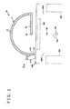
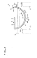
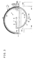
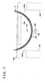
- FIGS. 1 to 8 are sectional views for sequentially illustrating a using method in a first embodiment of a medical tube (medical tube assembly) and a puncture needle according to the present invention
- FIG. 9 is a diagram (side view) as viewed along arrow A in FIG. 1
- FIG. 10 is an enlarged detailed view of region [B] surrounded by an alternate long and short dash line in FIG. 3
- FIG. 11 is a diagram as viewed along arrow C in FIG. 10
- FIG. 12 is a sectional view taken along line D-D in FIG. 4
- FIG. 13 shows diagrams as viewed along arrow E in FIG.
- a medical tube assembly 1 shown in FIGS. 4 to 6 includes a medical tube (tube) 2, and an implant 8 which is inserted in the medical tube 2.
- the medical tube assembly 1 is a medical device to be used in treatment of female urinary incontinence.
- a puncture apparatus 10 is also used together with the medical tube assembly 1, as shown in FIGS. 1 to 4 . It can be said that in this embodiment, the medical tube assembly 1 and the puncture apparatus 10 together constitute a "medical device set" for treatment of female urinary incontinence.
- the configuration of each of the components will now be described below.
- the implant 8 is a device which, commonly called “sling,” is an implantable device for treatment of female urinary incontinence, specifically, for supporting a urethra 100 in the manner of, for example, pulling the urethra 100 in a direction for spacing away from a vagina 200 when the urethra 100 would otherwise be going to move toward the vagina 200 side (see FIG. 8 ).
- the implant 8 includes a band-like (elongated) member which is flexible (see FIGS. 3 to 8 ).
- the constituent material of the implant 8 is not specifically restricted. Examples of the material applicable here include various resin materials that are biocompatible.
- the implant 8 may be preliminarily inserted (stored or housed) in the medical tube 2 as depicted in FIG. 3 , or may be inserted into the medical tube 2 in the course of a procedure. Where the implant 8 is preliminarily inserted in the medical tube 2, it is possible to swiftly perform a procedure. Where the implant 8 is inserted into the medical tube 2 in the course of a procedure, on the other hand, an implant 8 suited to an individual case can be selected in each procedure according to the case. In this embodiment, a case where the implant 8 is preliminarily inserted in the medical tube 2 will be described on a representative basis.
- the puncture apparatus 10 includes a puncture member 3, and a support member 20 which supports the puncture member 3 so that the puncture member 3 is rotatable.
- the puncture apparatus 10 may further include a bar-shaped urethral-insertion member to be inserted in the urethra 100, and a bar-shaped vaginal-insertion member to be inserted into the vagina 200. These members are preferably supported on and fixed to the support member 20 individually.
- the puncture member 3 includes a puncture needle 31 configured to puncture a living body tissue 700, an axial portion 33, and an interlock portion 32 interlocking the puncture needle 31 and the axial portion 33 to each other.
- the puncture needle 31 has a sharp needle tip 315 at a distal end thereof, and is bent in an arc shape centered on the axial portion 33.
- the axis of the puncture needle 31 and the axis of the axial portion 33 are in the relationship of skew lines. This ensures that when the puncture member 3 is rotationally moved about the axial portion 33, the needle tip 315 of the puncture needle 31 is moved along the arc, in a plane orthogonal to the axis of the axial portion 33, namely, in a plane to which the axis of the axial portion 33 is a normal.
- a center angle of the arc of the puncture needle 31 is not particularly limited, and may be appropriately set according to various conditions, in such a manner that when the living body tissue 700 is punctured by the puncture needle 31, the a piercing hole (puncture hole) 500 in an arc shape is formed in the living body tissue 700 as will be described later.
- Such a center angle is preferably 120 to 270 degrees, more preferably 160 to 230 degrees, and further preferably 180 to 210 degrees.
- needle tip 315 of the puncture needle 31 is oriented counterclockwise in FIGS. 1 to 4 in this embodiment, this is not restrictive, and the needle tip 315 may be oriented clockwise in the figures.
- the puncture needle 31 may be formed with a tapered portion 316 where the outside diameter of the puncture needle 31 gradually increases along the proximal direction from the needle tip 315.
- the puncture needle 31 may be a solid needle or may be a hollow needle.
- the axial portion 33 constitutes a rotation axis for the puncture member 3 (puncture needle 31), and is disposed so as to be rotatable on the support member 20.
- the axial portion 33 penetrates the support member 20 along the left-right direction in the figure.
- a flange 331 and a flange 332 are formed respectively at a distal-side portion and a proximal side portion of the axial portion 33, with the support member 20 interposed therebetween.
- the axial portion 33 is provided, at an end portion on the side opposite to the puncture needle 31, with a grasping portion 34 as an operating portion for a rotary movement operation of the puncture member 3.
- the shape of the grasping portion 34 is a rectangular parallelepiped shape in this embodiment. At the time of putting the puncture member 3 into a rotary movement, the grasping portion 34 is grasped with fingers and rotated in a predetermined direction. Note that the shape of the grasping portion 34 is naturally not restricted to the just-mentioned.
- the interlock portion 32 is a portion which interlocks the proximal end of the puncture needle 31 and the axial portion 33.
- the constituent material of the puncture member 3 is not specifically restricted.
- Examples of the material usable here include various metallic materials such as stainless steel, aluminum or aluminum alloys, titanium or titanium alloys, etc.
- the support member 20 is a member which supports the puncture member 3 so that the puncture member 3 is rotatable. Note that the support member 20 is omitted in FIGS. 1 to 4 .
- the support member 20 restricts the position of the puncture member 30 so that when the puncture member 3 rotates and punctures the living body tissue 700, the needle tip 315 of the puncture needle 31 passes between the urethra 100 and the vagina 200. Accordingly, between the urethra 100 and the vagina 200 is formed the arc-shaped piercing hole 500 by the puncture needle 31.
- the constituent material of the support member 20 is not specifically restricted.
- various resin materials such as polyethylene, polypropylene, etc. can be used.
- the medical tube 2 is a tube having a distal end opening 21 where the distal end thereof is open, and a proximal end opening 22 where the proximal end thereof is open.
- the medical tube 2 is formed therein with a lumen 25 opening into the distal end opening 21 and the proximal end opening 22.
- the implant 8 can be inserted in the lumen 25. Note that while only one lumen is formed in this embodiment, the number of the lumen(s) is not limited to one, and may be, for example, two or more.
- the medical tube 2 has a bent region 231 where an intermediate portion in the longitudinal direction thereof is bent in an arc shape.
- the medical tube 2 is rigid at least at the bent region 231.
- the term "rigid” used here means an extent of rigidity such that the bent region 231 can maintain its arc-shaped bent state by itself.
- the degree of bending (curvature) of the bent region 231 is preferably comparable to or lower than that of the puncture needle 31 of the puncture apparatus 10.
- the just-mentioned configuration ensures that when the medical tube 2 is inserted into the piercing hole 500 formed by the puncture apparatus 10, the bent region 231 is prevented from being flattened (pressed) inside the piercing hole 500, and the bent region 231 can easily follow the bent shape of the piercing hole 500. Consequently, an operation of inserting the medical tube 2 into the piercing hole 500 (living body) together with the implant 8 can be carried out easily and reliably. Besides, with the medical tube 2 separated (as will be described later) after the inserting operation, the implant 8 can be indwelled in the piercing hole 500 easily and assuredly (see FIG. 6 ).
- the cross-sectional shape of the bent region 231, or the cross-sectional shape of that portion of the medical tube 2 which is on the more distal side than the vicinity of the proximal end opening 22 (connection portion 232), is a somewhat flat shape, specifically, an elliptic shape.
- This cross-sectional shape ensures that in the case where the band-shaped implant 8 is preliminarily inserted in the lumen 25, the inserting operation can be carried out easily. It also ensures that it is possible to form a space for reliable insertion of the implant 8 in the piercing hole 500. It further ensures that the orientation of the implant 8 can be restricted.
- cross-sectional shape of the bent region 231 may be other shape than the somewhat flat shape, for example, a circular shape.
- the thickness direction (minor-diameter direction) of the somewhat flat shape is oriented toward the center of bending (curvature) O of the bent region 231.
- This configuration contributes more to easy insertion of the medical tube 2 into the piercing hole 500, as compared with the case where the width direction (major-diameter direction) of the somewhat flat shape is oriented toward the center of bending (curvature) O.
- the medical tube 2 is provided, in the vicinity of the proximal end opening 22, with the connection portion (tube-side connection portion) 232 into which the puncture needle 31 of the puncture member 3 is to be inserted and connected from the needle tip 315 side.
- the puncture needle 31 is provided at its distal end portion with a connection portion (puncture needle side connection portion) 317 to which the connection portion 232 (proximal end portion) of the medical tube 2 is to be connected.
- connection portion 232 of the medical tube 2 has a small piece 232a at a portion on an outer side with respect to the bend.
- the small piece 232a is configured by forming a roughly U-shaped slit 232b that penetrates the tube wall of the medical tube 2, and bending the portion surrounded by the slit 232b toward the inner side.
- the slit 232b is inverted U-shaped in FIG. 11 ; in other words, the U-shape is opening toward the proximal side (toward the lower side in FIG. 11 ).
- connection portion 317 of the puncture needle 31 has a cutout 317a where the connection portion 317 is partly lost.
- the cutout 317a is located immediately on the proximal side of, and on the outer side with respect to the bend of, the needle tip 315.
- the cutout 317a is formed in a wedge-like shape such that the depth thereof gradually decreases along the proximal direction (along the downward direction in FIG. 10 ).
- connection portion 232 of the medical tube 2 and the connection portion 317 of the puncture needle 31 are connected to each other (this state will hereinafter be referred to as the "connected state")
- this state will hereinafter be referred to as the "connected state”
- the small piece 232a of the connection portion 232 engages the cutout 317a of the connection portion 317. This ensures that the connected state is maintained reliably, in other words, an unintended canceling of the connected state is prevented.
- the medical tube 2 can be pulled in that direction.
- the medical tube 2 can be easily inserted into and passed through the piercing hole 500, and the subsequent indwelling of the implant 8 into the piercing hole 500 can be performed easily.
- connection portion 232 may be rigid like the bent region 231 or may, instead, be soft or flexible.
- the medical tube 2 is so configured that it can be separated (divided), at an intermediate portion in the longitudinal direction thereof, into a first tube 233 on the distal side and a second tube 234 on the proximal side.
- This separation (division) makes it possible to swiftly draw the medical tube 2 out of the piercing hole 500 and, therefore, to leave only the implant 8 indwelling in the piercing hole 500.
- a separation portion 235 for this separation (division) is located at a central portion in the longitudinal direction of the bent region 231. This enables the urethra 100 to be suitably supported by the implant 8 upon separation (division) of the medical tube 2 at the separation portion 235, as depicted in FIG. 6 .
- markers 27 for grasping of the central portion in the longitudinal direction of the bent region 231 are provided respectively at a distal portion and a proximal portion of the medical tube 2 (see FIG. 5 ).
- the markers 27 enable reliable grasping of the position of the central portion in the longitudinal direction of the bent region 231, namely, the position of the separation portion 235.
- the markers 27 are provided respectively at both the distal portion and the proximal portion of the medical tube 2 in this embodiment, this configuration is not restrictive, and, for example, a marker may only be provided at one of the distal portion and the proximal portion of the medical tube 2.
- the separation portion 235 constitutes a fitting structure in which a proximal end portion 236 of the first tube 233 fits inside a distal end portion 237 of the second tube 234. This ensures that when the medical tube 2 is pulled from both sides thereof, the fitting state between the proximal end portion 236 of the first tube 233 and the distal end portion 237 of the second tube 234 can be canceled in an assured manner. By this canceling of the fit, the medical tube 2 can be easily separated at the separation portion 235 into the first tube 233 and the second tube 234.
- proximal end portion 236 of the first tube 233 is formed with a gradually decreasing width portion 238 where the width thereof gradually decreases along proximally. This ensures that when the medical tube 2 is to be left in the state as depicted in FIG. 13(a) , the proximal end portion 236 of the first tube 233 can be easily inserted into the distal end portion 237 of the second tube 234, resulting in the fitting state between the end portions.
- the outside width (maximum width) w 1 of the proximal end portion 236 of the first tube 233 is equal to or slightly smaller than the inside width w 2 of the distal end portion 237 of the second tube 234. This permits easier insertion of the proximal end portion 236 of the first tube 233 into the distal end portion 237 of the second tube 234.
- the fitting structure between the proximal end portion 236 of the first tube 233 and the distal end portion 237 of the second tube 234 is such that the proximal end portion 236 is located on the inner side and is located on the outer side of the distal end portion 237.
- the separation portion 235 specifically, in the boundary area between the proximal end portion 236 and the distal end portion 237, there is formed a step 239 where the width of the medical tube 2 is reduced stepwise along the distal direction (see FIG. 13(a) ). Since the medical tube 2 is inserted into the piercing hole 500, starting from the proximal end thereof, it is preferable that the step 239 is formed in the just-mentioned fashion.
- the medical tube 2 preferably has a whole length which is longer than the whole length of the puncture needle 31. Accordingly, the medical tube 2 is longer than the whole length of the piercing hole 500 formed by the puncture needle 31, so that both end portions of the medical tube 2 protrude from the piercing hole 500 in a state where the medical tube 2 is inserted in and passed through the piercing hole 500 as illustrated in FIGS. 4 and 5 .
- the pulling-out operation can be performed by grasping the protruding end portions.
- the constituent material of the medical tube 2 is not specifically restricted.
- the material applicable here include polyolefins such as polyethylene, polypropylene, ethylene-vinyl acetate copolymer, etc., modified polyolefins, polyamides (e.g., nylon 6, nylon 46, nylon 66, nylon 610, nylon 612, nylon 11, nylon 12, nylon 6-12, and nylon 6-66), thermoplastic polyimides, liquid crystal polymers such as aromatic polyesters, etc., polyphenylene oxide, polyphenylene sulfide, polycarbonate, polymethyl methacrylate, polyethers, polyether-ether ketone, polyether-imides, polyacetal, various thermoplastic elastomers based on styrene, polyolefin, polyvinyl chloride, polyurethane, polyester, polyamide, polybutadiene, trans-polyisoprene, fluoro-rubber, chlorinated polyethylene or the like, and copolymers, polymer blends, polymer
- FIGS. 1 to 8 An exemplary method of using the medical tube assembly 1 and the puncture apparatus 10 will be described below, referring to FIGS. 1 to 8 .
- the implant 8 has preliminarily been housed in the medical tube 2 and is inserted into the piercing hole 500 together with the medical tube 2.
- the medical tube 2 is rigid, at least at its bent region 231, as aforementioned. Therefore, the medical tube 2 is prevented from being unintendedly deformed through being flattened or pressed by the living body tissue 700 when situated in the piercing hole 500. Accordingly, the operation of inserting the implant 8 (together with the medical tube 2) into the piercing hole 500 can be carried out easily and reliably.
- the medical tube 2 can be easily pulled out of the piercing hole 500 through the separation thereof, after the implant 8 is inserted into the piercing hole 500 together with the medical tube 2. Consequently, the implant 8 is indwelled in the piercing hole 500 in a reliable manner.
- the puncture needle 31 can be pulled proximally together with the medical tube 2. This ensures that the medical tube 2 can easily be inserted into and passed through the piercing hole 500, and the subsequent indwelling of the implant 8 into the piercing hole 500 can also be carried out easily.
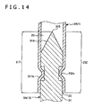
- FIG. 14 is a longitudinal sectional view showing a second embodiment of the medical tube (medical tube assembly) and the puncture needle according to the present invention.
- the second embodiment of the medical tube, medical tube assembly and puncture needle according to the present invention will be described below.
- description will be mainly made of differences of the second embodiment from the aforementioned first embodiment, and the same or similar items to those described above will be omitted from the description.
- This embodiment is the same as the first embodiment above, except for differences in the configurations of connection portions of the medical tube and the puncture needle.
- a connection portion 232 of a medical tube 2A has a reduced-diameter part 232c where the medical tube 2A is reduced in inside diameter.
- the reduced-diameter part 232c is formed, for example, by heat shrinkage of that portion of the medical tube 2A which is to be the reduced-diameter part 232c.
- a connection portion 317 of a puncture needle 31 of a puncture member 3A has a reduced-diameter part 317b where the puncture needle 31 is reduced in outside diameter at a position immediately on the proximal side of a tapered portion 316 of a needle tip 315.
- the reduced-diameter part 317b is formed, for example, by cutting that portion of the puncture needle 31 which is to be the reduced-diameter part 317b.
- the reduced-diameter part 232c of the connection portion 232 of the medical tube 2A is in engagement with the reduced-diameter part 317b of the connection portion 317 of the puncture needle 31.
- the connected state is maintained securely. Consequently, the medical tube 2A can be made to pass a piercing hole 500, following the puncture member 3A, as aforementioned.
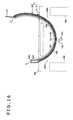
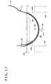
- FIGS. 15 to 17 are sectional views for sequentially illustrating a using method in a third embodiment of the medical tube (medical tube assembly) according to the present invention.
- This embodiment is the same as the first embodiment above, except that the separation portion is omitted from the medical tube.
- a medical tube 2B in this embodiment has a configuration wherein a separation portion, such as the separation portion 235 possessed by the medical tube 2 in the first embodiment above, is omitted.
- a distal portion 81 of an implant 8 is preliminarily set protruding from a distal end opening 21 of the medical tube 2B.
- FIGS. 15 to 17 An exemplary method of using a medical tube assembly 1 possessing the medical tube 2B configured as above will be described, referring to FIGS. 15 to 17 . Note that this using method is the same as the using method in the first embodiment above in operations [1] to [3] and operations [7] and [8], but is different from the using method in the first embodiment in operations [4] to [6]. Here, the different operations will be described.
- the medical tube assembly 1 with the implant 8 inserted in the medical tube 2B is prepared.
- the distal portion 81 of the implant 8 is protruding from the distal end opening 21 of the medical tube 2B.
- the puncture member 3 is rotated clockwise in FIG. 15 , as shown in the figure. By this rotation, the puncture member 3 is pulled out of the piercing hole 500, and, this time, the medical tube assembly 1 (medical tube 2B) is inserted into and passed through the piercing hole 500. Besides, the medical tube assembly 1 is in a state where its distal-side portion is protruding from the body surface 600 on the side of the obturator foramen 400b, whereas its proximal-side portion is protruding from the body surface 600 on the side of the obturator foramen 400a. Even in this state, the distal portion 81 of the implant 8 is protruding from the distal end opening 21 of the medical tube 2B.
- the distal portion 81 of the implant 8 is preliminarily set protruding from the distal end opening 21, this is not restrictive.
- the distal portion 81 may be set retracted to the depth side from the distal end opening 21.
- Such a configuration ensures that upon separation of the distal portion, the distal portion 81 of the implant 8 protrudes from the medical tube 2B. By separating the distal portion after the operation [5'], then, it is possible to carry out the operation [6'] in an assured manner.
- Each of the medical tube, the medical tube assembly and the puncture needle disclosed here may be a combination of arbitrary two or more configurations (features) of the above embodiments.
- the bent region of the medical tube maintains its state of being bent in an arc shape by its own rigidity
- the bent state of the bent region may be maintained, for example, by a method in which a rigid stylet or the like having a bent region bent in an arc shape is inserted in the medical tube.
- the separation portion of the medical tube may include a perforation.
- the medical tube according to the present invention is a medical tube in which to insert an elongated implant.
- the medical tube is composed essentially of a tube having a distal end opening where the tube is open at its distal end, and a proximal end opening where the tube is open at its proximal end.
- the tube has a bent region where an intermediate portion in the longitudinal direction of the tube is bent and the bent state is maintained.
- the tube also has a connection portion which is provided at the proximal end opening and to which a puncture needle having a sharp needle tip at its distal end is connected from the needle tip side.
- the medical tube assembly according to the present invention has industrial applicability.
Landscapes
- Health & Medical Sciences (AREA)
- Life Sciences & Earth Sciences (AREA)
- Surgery (AREA)
- Biomedical Technology (AREA)
- General Health & Medical Sciences (AREA)
- Engineering & Computer Science (AREA)
- Heart & Thoracic Surgery (AREA)
- Veterinary Medicine (AREA)
- Public Health (AREA)
- Animal Behavior & Ethology (AREA)
- Medical Informatics (AREA)
- Nuclear Medicine, Radiotherapy & Molecular Imaging (AREA)
- Molecular Biology (AREA)
- Pathology (AREA)
- Oral & Maxillofacial Surgery (AREA)
- Vascular Medicine (AREA)
- Cardiology (AREA)
- Transplantation (AREA)
- Surgical Instruments (AREA)
- Prostheses (AREA)
- Urology & Nephrology (AREA)
Applications Claiming Priority (1)
| Application Number | Priority Date | Filing Date | Title |
|---|---|---|---|
| PCT/JP2012/071593 WO2014033812A1 (fr) | 2012-08-27 | 2012-08-27 | Tube médical, ensemble tube médical et aiguille de ponction |
Publications (2)
| Publication Number | Publication Date |
|---|---|
| EP2889017A1 true EP2889017A1 (fr) | 2015-07-01 |
| EP2889017A4 EP2889017A4 (fr) | 2016-03-16 |
Family
ID=50182663
Family Applications (1)
| Application Number | Title | Priority Date | Filing Date |
|---|---|---|---|
| EP12883448.8A Withdrawn EP2889017A4 (fr) | 2012-08-27 | 2012-08-27 | Tube médical, ensemble tube médical et aiguille de ponction |
Country Status (4)
| Country | Link |
|---|---|
| US (1) | US10292731B2 (fr) |
| EP (1) | EP2889017A4 (fr) |
| JP (1) | JP5919382B2 (fr) |
| WO (1) | WO2014033812A1 (fr) |
Cited By (1)
| Publication number | Priority date | Publication date | Assignee | Title |
|---|---|---|---|---|
| EP2982311A4 (fr) * | 2013-04-01 | 2016-09-21 | Terumo Corp | Tube médical et ensemble tube médical |
Families Citing this family (5)
| Publication number | Priority date | Publication date | Assignee | Title |
|---|---|---|---|---|
| US8911464B2 (en) * | 2012-03-23 | 2014-12-16 | Terumo Kabushiki Kaisha | Puncture apparatus |
| WO2014162422A1 (fr) * | 2013-04-01 | 2014-10-09 | テルモ株式会社 | Ensemble aiguille de ponction |
| WO2015137115A1 (fr) * | 2014-03-13 | 2015-09-17 | テルモ株式会社 | Élément de ponction |
| ES2528069B1 (es) * | 2014-09-12 | 2015-11-11 | Julio SAINZ LÓPEZ | Dispositivo para colocar un catéter en un punto de aplicación de un fármaco con control directo mediante ecógrafo |
| KR20210107078A (ko) * | 2018-12-24 | 2021-08-31 | 쇼오트 아게 | 개선된 파괴 강도 및 구강 촉감을 가진 음용 도구 |
Family Cites Families (17)
| Publication number | Priority date | Publication date | Assignee | Title |
|---|---|---|---|---|
| IL119151A0 (en) * | 1996-06-10 | 1996-11-14 | Influence Med Tech Ltd | Surgical suture insertion device and method for treatment of urinary stress incontinence using fixation to bone |
| AU6329498A (en) * | 1997-02-13 | 1998-09-08 | Boston Scientific Ireland Limited, Barbados Head Office | Percutaneous and hiatal devices and methods for use in minimally invasive pelvicsurgery |
| US7121997B2 (en) * | 1999-06-09 | 2006-10-17 | Ethicon, Inc. | Surgical instrument and method for treating female urinary incontinence |
| ATE452595T1 (de) * | 2000-09-26 | 2010-01-15 | Ethicon Inc | Chirurgisches gerät zur abgabe einer schlinge bei der behandlung von harninkontinenz bei frauen |
| FR2814939B1 (fr) * | 2000-10-05 | 2002-12-20 | Sofradim Production | Ensemble de soutenement sous-uretral dans le traitement de l'incontinence urinaire d'effort de la femme |
| US6612977B2 (en) * | 2001-01-23 | 2003-09-02 | American Medical Systems Inc. | Sling delivery system and method of use |
| US7364541B2 (en) | 2001-03-09 | 2008-04-29 | Boston Scientific Scimed, Inc. | Systems, methods and devices relating to delivery of medical implants |
| US20040153008A1 (en) * | 2001-06-05 | 2004-08-05 | Yehuda Sharf | Probe anchor |
| JP4476630B2 (ja) | 2002-03-07 | 2010-06-09 | エーエムエス・リサーチ・コーポレーション | 閉鎖膜経由での手術器具および方法 |
| WO2004016196A2 (fr) * | 2002-08-14 | 2004-02-26 | Boston Scientific Limited | Systemes, procedes et dispositifs relatifs a la pose d'implants medicaux |
| US20040102808A1 (en) * | 2002-11-26 | 2004-05-27 | Voss Laveille Kao | Needle for retrieving a suture |
| EP2543341B1 (fr) * | 2004-06-14 | 2016-07-20 | Boston Scientific Limited | Ancre de tissu mou |
| KR100593659B1 (ko) * | 2004-07-21 | 2006-06-28 | 삼성전자주식회사 | 원자층 적층 방법과 이를 이용한 게이트 구조물의 제조방법 및 커패시터의 제조 방법 |
| AU2006210494B2 (en) * | 2005-02-04 | 2011-01-06 | Ams Research Corporation | Needle design for male transobturator sling |
| US7637860B2 (en) * | 2005-11-16 | 2009-12-29 | Boston Scientific Scimed, Inc. | Devices for minimally invasive pelvic surgery |
| US8414468B2 (en) * | 2009-08-18 | 2013-04-09 | Eric Sokol | Anal sling system and method to treat fecal incontinence |
| US9271754B2 (en) * | 2010-12-16 | 2016-03-01 | Boston Scientific Scimed, Inc. | Movable curved needle for delivering implants and methods of delivering implants |
-
2012
- 2012-08-27 JP JP2014532593A patent/JP5919382B2/ja not_active Expired - Fee Related
- 2012-08-27 WO PCT/JP2012/071593 patent/WO2014033812A1/fr not_active Ceased
- 2012-08-27 EP EP12883448.8A patent/EP2889017A4/fr not_active Withdrawn
-
2015
- 2015-02-27 US US14/633,469 patent/US10292731B2/en active Active
Cited By (2)
| Publication number | Priority date | Publication date | Assignee | Title |
|---|---|---|---|---|
| EP2982311A4 (fr) * | 2013-04-01 | 2016-09-21 | Terumo Corp | Tube médical et ensemble tube médical |
| US10143468B2 (en) | 2013-04-01 | 2018-12-04 | Terumo Kabushiki Kaisha | Medical tube and medical tube assembly |
Also Published As
| Publication number | Publication date |
|---|---|
| JP5919382B2 (ja) | 2016-05-18 |
| US10292731B2 (en) | 2019-05-21 |
| US20150164549A1 (en) | 2015-06-18 |
| WO2014033812A1 (fr) | 2014-03-06 |
| EP2889017A4 (fr) | 2016-03-16 |
| JPWO2014033812A1 (ja) | 2016-08-08 |
Similar Documents
| Publication | Publication Date | Title |
|---|---|---|
| US12097106B2 (en) | Insertion device for delivery of a mesh carrier | |
| US10292731B2 (en) | Medical tube, medical tube assembly and puncture needle | |
| US10548702B2 (en) | Systems and methods for sling delivery and placement | |
| US9955995B2 (en) | Puncture device and puncture apparatus | |
| US10258374B2 (en) | Puncture apparatus | |
| WO2013140818A1 (fr) | Appareil de perforation | |
| EP2370000A1 (fr) | Dispositif d'insertion et procédé de délivrance d'un support à mailles | |
| JPH0624533B2 (ja) | 医療用器具 | |
| US20150164627A1 (en) | Medical tube and medical tube assembly | |
| US9498210B2 (en) | Puncture apparatus | |
| US9017357B1 (en) | Puncture apparatus | |
| US20150080644A1 (en) | Implant and method of placing implant indwelling | |
| US10231731B2 (en) | Puncture needle assembly | |
| US10076353B2 (en) | Medical device | |
| US20160015501A1 (en) | Medical device | |
| US9713517B2 (en) | Method of placing implant indwelling | |
| JP4500282B2 (ja) | 生体用縫合具 | |
| US20160008119A1 (en) | Tube assembly | |
| US20160175081A1 (en) | Medical tube, medical device set, and method of placing implant indwelling |
Legal Events
| Date | Code | Title | Description |
|---|---|---|---|
| PUAI | Public reference made under article 153(3) epc to a published international application that has entered the european phase |
Free format text: ORIGINAL CODE: 0009012 |
|
| 17P | Request for examination filed |
Effective date: 20150223 |
|
| AK | Designated contracting states |
Kind code of ref document: A1 Designated state(s): AL AT BE BG CH CY CZ DE DK EE ES FI FR GB GR HR HU IE IS IT LI LT LU LV MC MK MT NL NO PL PT RO RS SE SI SK SM TR |
|
| AX | Request for extension of the european patent |
Extension state: BA ME |
|
| DAX | Request for extension of the european patent (deleted) | ||
| RA4 | Supplementary search report drawn up and despatched (corrected) |
Effective date: 20160217 |
|
| RIC1 | Information provided on ipc code assigned before grant |
Ipc: A61B 17/00 20060101ALI20160211BHEP Ipc: A61F 2/08 20060101AFI20160211BHEP |
|
| 17Q | First examination report despatched |
Effective date: 20170310 |
|
| STAA | Information on the status of an ep patent application or granted ep patent |
Free format text: STATUS: THE APPLICATION IS DEEMED TO BE WITHDRAWN |
|
| 18D | Application deemed to be withdrawn |
Effective date: 20170721 |