EP2889088A2 - Dispositif de traitement de gaz de carneau - Google Patents
Dispositif de traitement de gaz de carneau Download PDFInfo
- Publication number
- EP2889088A2 EP2889088A2 EP14181299.0A EP14181299A EP2889088A2 EP 2889088 A2 EP2889088 A2 EP 2889088A2 EP 14181299 A EP14181299 A EP 14181299A EP 2889088 A2 EP2889088 A2 EP 2889088A2
- Authority
- EP
- European Patent Office
- Prior art keywords
- flue gas
- flue
- gas treatment
- treatment device
- electrostatic precipitator
- Prior art date
- Legal status (The legal status is an assumption and is not a legal conclusion. Google has not performed a legal analysis and makes no representation as to the accuracy of the status listed.)
- Withdrawn
Links
- UGFAIRIUMAVXCW-UHFFFAOYSA-N Carbon monoxide Chemical compound [O+]#[C-] UGFAIRIUMAVXCW-UHFFFAOYSA-N 0.000 title claims abstract description 252
- 239000003546 flue gas Substances 0.000 title claims abstract description 252
- 230000007704 transition Effects 0.000 claims abstract description 52
- 239000012719 wet electrostatic precipitator Substances 0.000 claims abstract description 42
- 238000004891 communication Methods 0.000 claims description 16
- 239000002803 fossil fuel Substances 0.000 claims description 7
- 230000002457 bidirectional effect Effects 0.000 abstract description 6
- 238000005516 engineering process Methods 0.000 description 8
- 239000002253 acid Substances 0.000 description 7
- 239000003344 environmental pollutant Substances 0.000 description 3
- 229910001385 heavy metal Inorganic materials 0.000 description 3
- 206010022000 influenza Diseases 0.000 description 3
- 230000010354 integration Effects 0.000 description 3
- 239000003595 mist Substances 0.000 description 3
- 231100000719 pollutant Toxicity 0.000 description 3
- XLYOFNOQVPJJNP-UHFFFAOYSA-N water Substances O XLYOFNOQVPJJNP-UHFFFAOYSA-N 0.000 description 3
- 239000003245 coal Substances 0.000 description 2
- 238000005260 corrosion Methods 0.000 description 2
- 230000007797 corrosion Effects 0.000 description 2
- 239000000428 dust Substances 0.000 description 2
- 238000007667 floating Methods 0.000 description 2
- 229910052602 gypsum Inorganic materials 0.000 description 2
- 239000010440 gypsum Substances 0.000 description 2
- VNWKTOKETHGBQD-UHFFFAOYSA-N methane Chemical compound C VNWKTOKETHGBQD-UHFFFAOYSA-N 0.000 description 2
- 239000007787 solid Substances 0.000 description 2
- 150000007513 acids Chemical class 0.000 description 1
- 238000006243 chemical reaction Methods 0.000 description 1
- 150000001805 chlorine compounds Chemical class 0.000 description 1
- 238000010276 construction Methods 0.000 description 1
- 238000005536 corrosion prevention Methods 0.000 description 1
- 230000003247 decreasing effect Effects 0.000 description 1
- 238000006477 desulfuration reaction Methods 0.000 description 1
- 230000023556 desulfurization Effects 0.000 description 1
- 150000002222 fluorine compounds Chemical class 0.000 description 1
- 238000010438 heat treatment Methods 0.000 description 1
- 239000007788 liquid Substances 0.000 description 1
- 239000007769 metal material Substances 0.000 description 1
- 238000000034 method Methods 0.000 description 1
- 230000004048 modification Effects 0.000 description 1
- 238000012986 modification Methods 0.000 description 1
- 239000003345 natural gas Substances 0.000 description 1
- 230000000630 rising effect Effects 0.000 description 1
- 229920006395 saturated elastomer Polymers 0.000 description 1
- 239000000779 smoke Substances 0.000 description 1
- 239000000126 substance Substances 0.000 description 1
- XTQHKBHJIVJGKJ-UHFFFAOYSA-N sulfur monoxide Chemical class S=O XTQHKBHJIVJGKJ-UHFFFAOYSA-N 0.000 description 1
- 229910052815 sulfur oxide Inorganic materials 0.000 description 1
- 230000000007 visual effect Effects 0.000 description 1
Images











Classifications
-
- B—PERFORMING OPERATIONS; TRANSPORTING
- B03—SEPARATION OF SOLID MATERIALS USING LIQUIDS OR USING PNEUMATIC TABLES OR JIGS; MAGNETIC OR ELECTROSTATIC SEPARATION OF SOLID MATERIALS FROM SOLID MATERIALS OR FLUIDS; SEPARATION BY HIGH-VOLTAGE ELECTRIC FIELDS
- B03C—MAGNETIC OR ELECTROSTATIC SEPARATION OF SOLID MATERIALS FROM SOLID MATERIALS OR FLUIDS; SEPARATION BY HIGH-VOLTAGE ELECTRIC FIELDS
- B03C3/00—Separating dispersed particles from gases or vapour, e.g. air, by electrostatic effect
- B03C3/019—Post-treatment of gases
-
- B—PERFORMING OPERATIONS; TRANSPORTING
- B03—SEPARATION OF SOLID MATERIALS USING LIQUIDS OR USING PNEUMATIC TABLES OR JIGS; MAGNETIC OR ELECTROSTATIC SEPARATION OF SOLID MATERIALS FROM SOLID MATERIALS OR FLUIDS; SEPARATION BY HIGH-VOLTAGE ELECTRIC FIELDS
- B03C—MAGNETIC OR ELECTROSTATIC SEPARATION OF SOLID MATERIALS FROM SOLID MATERIALS OR FLUIDS; SEPARATION BY HIGH-VOLTAGE ELECTRIC FIELDS
- B03C3/00—Separating dispersed particles from gases or vapour, e.g. air, by electrostatic effect
- B03C3/017—Combinations of electrostatic separation with other processes, not otherwise provided for
-
- B—PERFORMING OPERATIONS; TRANSPORTING
- B01—PHYSICAL OR CHEMICAL PROCESSES OR APPARATUS IN GENERAL
- B01D—SEPARATION
- B01D53/00—Separation of gases or vapours; Recovering vapours of volatile solvents from gases; Chemical or biological purification of waste gases, e.g. engine exhaust gases, smoke, fumes, flue gases, aerosols
- B01D53/32—Separation of gases or vapours; Recovering vapours of volatile solvents from gases; Chemical or biological purification of waste gases, e.g. engine exhaust gases, smoke, fumes, flue gases, aerosols by electrical effects other than those provided for in group B01D61/00
- B01D53/323—Separation of gases or vapours; Recovering vapours of volatile solvents from gases; Chemical or biological purification of waste gases, e.g. engine exhaust gases, smoke, fumes, flue gases, aerosols by electrical effects other than those provided for in group B01D61/00 by electrostatic effects or by high-voltage electric fields
-
- B—PERFORMING OPERATIONS; TRANSPORTING
- B01—PHYSICAL OR CHEMICAL PROCESSES OR APPARATUS IN GENERAL
- B01D—SEPARATION
- B01D53/00—Separation of gases or vapours; Recovering vapours of volatile solvents from gases; Chemical or biological purification of waste gases, e.g. engine exhaust gases, smoke, fumes, flue gases, aerosols
- B01D53/34—Chemical or biological purification of waste gases
- B01D53/343—Heat recovery
-
- B—PERFORMING OPERATIONS; TRANSPORTING
- B01—PHYSICAL OR CHEMICAL PROCESSES OR APPARATUS IN GENERAL
- B01D—SEPARATION
- B01D53/00—Separation of gases or vapours; Recovering vapours of volatile solvents from gases; Chemical or biological purification of waste gases, e.g. engine exhaust gases, smoke, fumes, flue gases, aerosols
- B01D53/34—Chemical or biological purification of waste gases
- B01D53/46—Removing components of defined structure
- B01D53/48—Sulfur compounds
- B01D53/50—Sulfur oxides
- B01D53/501—Sulfur oxides by treating the gases with a solution or a suspension of an alkali or earth-alkali or ammonium compound
-
- B—PERFORMING OPERATIONS; TRANSPORTING
- B01—PHYSICAL OR CHEMICAL PROCESSES OR APPARATUS IN GENERAL
- B01D—SEPARATION
- B01D53/00—Separation of gases or vapours; Recovering vapours of volatile solvents from gases; Chemical or biological purification of waste gases, e.g. engine exhaust gases, smoke, fumes, flue gases, aerosols
- B01D53/34—Chemical or biological purification of waste gases
- B01D53/74—General processes for purification of waste gases; Apparatus or devices specially adapted therefor
- B01D53/75—Multi-step processes
-
- B—PERFORMING OPERATIONS; TRANSPORTING
- B03—SEPARATION OF SOLID MATERIALS USING LIQUIDS OR USING PNEUMATIC TABLES OR JIGS; MAGNETIC OR ELECTROSTATIC SEPARATION OF SOLID MATERIALS FROM SOLID MATERIALS OR FLUIDS; SEPARATION BY HIGH-VOLTAGE ELECTRIC FIELDS
- B03C—MAGNETIC OR ELECTROSTATIC SEPARATION OF SOLID MATERIALS FROM SOLID MATERIALS OR FLUIDS; SEPARATION BY HIGH-VOLTAGE ELECTRIC FIELDS
- B03C3/00—Separating dispersed particles from gases or vapour, e.g. air, by electrostatic effect
- B03C3/02—Plant or installations having external electricity supply
- B03C3/025—Combinations of electrostatic separators, e.g. in parallel or in series, stacked separators or dry-wet separator combinations
-
- B—PERFORMING OPERATIONS; TRANSPORTING
- B03—SEPARATION OF SOLID MATERIALS USING LIQUIDS OR USING PNEUMATIC TABLES OR JIGS; MAGNETIC OR ELECTROSTATIC SEPARATION OF SOLID MATERIALS FROM SOLID MATERIALS OR FLUIDS; SEPARATION BY HIGH-VOLTAGE ELECTRIC FIELDS
- B03C—MAGNETIC OR ELECTROSTATIC SEPARATION OF SOLID MATERIALS FROM SOLID MATERIALS OR FLUIDS; SEPARATION BY HIGH-VOLTAGE ELECTRIC FIELDS
- B03C3/00—Separating dispersed particles from gases or vapour, e.g. air, by electrostatic effect
- B03C3/02—Plant or installations having external electricity supply
- B03C3/16—Plant or installations having external electricity supply wet type
-
- B—PERFORMING OPERATIONS; TRANSPORTING
- B03—SEPARATION OF SOLID MATERIALS USING LIQUIDS OR USING PNEUMATIC TABLES OR JIGS; MAGNETIC OR ELECTROSTATIC SEPARATION OF SOLID MATERIALS FROM SOLID MATERIALS OR FLUIDS; SEPARATION BY HIGH-VOLTAGE ELECTRIC FIELDS
- B03C—MAGNETIC OR ELECTROSTATIC SEPARATION OF SOLID MATERIALS FROM SOLID MATERIALS OR FLUIDS; SEPARATION BY HIGH-VOLTAGE ELECTRIC FIELDS
- B03C3/00—Separating dispersed particles from gases or vapour, e.g. air, by electrostatic effect
- B03C3/34—Constructional details or accessories or operation thereof
- B03C3/82—Housings
-
- B—PERFORMING OPERATIONS; TRANSPORTING
- B01—PHYSICAL OR CHEMICAL PROCESSES OR APPARATUS IN GENERAL
- B01D—SEPARATION
- B01D2257/00—Components to be removed
- B01D2257/30—Sulfur compounds
- B01D2257/302—Sulfur oxides
-
- B—PERFORMING OPERATIONS; TRANSPORTING
- B01—PHYSICAL OR CHEMICAL PROCESSES OR APPARATUS IN GENERAL
- B01D—SEPARATION
- B01D2257/00—Components to be removed
- B01D2257/60—Heavy metals or heavy metal compounds
-
- B—PERFORMING OPERATIONS; TRANSPORTING
- B01—PHYSICAL OR CHEMICAL PROCESSES OR APPARATUS IN GENERAL
- B01D—SEPARATION
- B01D2258/00—Sources of waste gases
- B01D2258/02—Other waste gases
- B01D2258/0283—Flue gases
-
- B—PERFORMING OPERATIONS; TRANSPORTING
- B01—PHYSICAL OR CHEMICAL PROCESSES OR APPARATUS IN GENERAL
- B01D—SEPARATION
- B01D53/00—Separation of gases or vapours; Recovering vapours of volatile solvents from gases; Chemical or biological purification of waste gases, e.g. engine exhaust gases, smoke, fumes, flue gases, aerosols
- B01D53/34—Chemical or biological purification of waste gases
- B01D53/38—Removing components of undefined structure
- B01D53/40—Acidic components
-
- B—PERFORMING OPERATIONS; TRANSPORTING
- B01—PHYSICAL OR CHEMICAL PROCESSES OR APPARATUS IN GENERAL
- B01D—SEPARATION
- B01D53/00—Separation of gases or vapours; Recovering vapours of volatile solvents from gases; Chemical or biological purification of waste gases, e.g. engine exhaust gases, smoke, fumes, flue gases, aerosols
- B01D53/34—Chemical or biological purification of waste gases
- B01D53/46—Removing components of defined structure
- B01D53/64—Heavy metals or compounds thereof, e.g. mercury
Definitions
- the present application relates to the technical field of flue gas treatment, in particular to a flue gas treatment device for a fossil-fuel power plant.
- the ash content of coal has varied characteristics due to the diversification of coal sources of a fossil-fuel power plant, a conventional flue gas treatment device can only control the dust emission in a range of 20 to 100mg/Nm 3 , however, with the increased attention on PM2.5 and increasingly strict requirement for environment protection, the emission standard of the fossil-fuel power plant is required to reach a range of 20 to 30mg/Nm 3 , even an emission standard of 5mg/Nm 3 , which is similar to the emission requirement for the natural gas furnace, is required in developed regions.
- a wet electrostatic precipitator which is used in the chemical industry, is applied to the fossil-fuel power plant to meet the stricter requirement for dust emission.
- a wet desulphurization technology can remove most of SO 2 , and the flue gas after the wet desulphurization is a nearly saturated wet flue gas, and generally has a temperature about 50 Celsius degree, and if such flue gas enters a stack directly, the following issues will be caused.
- the temperature of about 50 Celsius degree is below several acid dew points of the flue gas.
- a small amount of sulfur oxides, which are not completely removed after the flue gas passes through a desulfurization reaction tower, and chlorides and fluorides, which are not removed can generate acids having a strong corrosivity in the presence of water, which causes serious corrosion to the subsequent flues and stacks, and threatens the safe running of the power plant.
- expensive metallic or non-metallic materials are generally used in the wet stack for corrosion prevention, which has a high requirement for cost and construction.
- the flue gas is passed through the wet electrostatic precipitator and a flue gas heater in sequence, and then is discharged into the stack.
- the wet electrostatic precipitator and the flue gas heater are located at different positions and the devices are independent, a large area is required for arranging these devices.
- each bidirectional transition flue can create a large pressure drop, and the flue gas has poor flow uniformity, thus a flow equalization orifice plate may be required which further increases the resistance, thereby causing a high pressure drop of the flue gas side, an increased pressure head of a draught fan, and an increased power consumption.
- an object of the present application is to provide a flue gas treatment device to reduce an occupied area of the device.
- a flue gas treatment device is provided, which is configured to be arranged between a wet desulphurization tower and a stack in a fossil-fuel power plant, wherein the flue gas treatment device includes an integrated flue housing, a wet electrostatic precipitator and a flue gas heater, the integrated flue housing has a flue gas inlet channel configured to communicate with the wet desulphurization tower, and a flue gas outlet channel configured to communicate with the stack; the wet electrostatic precipitator and the flue gas heater are arranged in the integrated flue housing in sequence, the wet electrostatic precipitator is in communication with the flue gas inlet channel, the flue gas heater is in communication with the flue gas outlet channel, and a first transition flue is formed in the integrated flue housing at a portion between the wet electrostatic precipitator and the flue gas heater.
- a first flue gas treatment unit is formed by one of the wet electrostatic precipitator and one of the flue gas heater which are arranged in a horizontal flow direction of flue gas.
- one to N groups of the first flue gas treatment units are provided, and in a case that multiple groups of the first flue gas treatment units are arranged, the multiple groups of the first flue gas treatment units are arranged to be overlapped with each other in a vertical height direction or arranged in parallel in a horizontal direction, or arranged in a combined manner of the overlapped arrangement in the vertical height direction and the parallel arrangement in the horizontal direction, and in each group of the first flue gas treatment unit, the flue gas inlet channel is in communication with the flue gas outlet channel.
- a second flue gas treatment unit is formed by one of the wet electrostatic precipitator and one of the flue gas heater which are arranged vertically.
- one to N groups of the second flue gas treatment units are provided, and in a case that multiple groups of the second flue gas treatment units are arranged, the multiple groups of the second flue gas treatment units are arranged in parallel in a horizontal direction, and in each group of the second flue gas treatment unit, the flue gas inlet channel is in communication with the flue gas outlet channel.
- a demister is further provided between the wet electrostatic precipitator and the flue gas heater, the first transition flue is located in the integrated flue housing at a portion between the wet electrostatic precipitator and the demister, and a second transition flue is formed in the integrated flue housing at a portion between the demister and the flue gas heater.
- the first transition flue and the second transition flue are both a one-way transition flue.
- the one-way transition flue has a large flue section and a small flue section, and a ratio of an area of the large flue section to an area of the small flue section is equal to or smaller than 2:1.
- a pretreatment demister is provided at a flue gas inlet side of the integrated flue housing.
- the flue gas from the wet desulphurization tower firstly passes through the wet electrostatic precipitator in the integrated flue housing, to remove most of fine dusts, gypsums, acid mist drips and heavy metals, thereby reducing pollutants to the air. Then, the flue gas is heated by the flue gas heater in the integrated flue housing, and finally enters the stack via a flue behind the flue gas integration device to be discharged into the air.
- the flue gas treatment device of the present application since the wet electrostatic precipitator and the flue gas heater are integrated in the integrated flue housing, the occupied area of the flue gas treatment device is smaller than that of the solution with devices being arranged separately.
- the flue gas since a bidirectional transition flue is not required to be arranged in the integrated flue housing, the flue gas has a good flow uniformity, and further it is not required to arrange a flow equalization orifice plate in the flue, thus the flue gas has a small resistance, thereby reducing the power consumption of the draught fan and increasing the efficiency of the power plant.
- the wet electrostatic precipitator, the demister and the flue gas heater belong to different technical fields, and are designed and supplied by different manufacturers, the quantity of the devices are usually different, and arrangement manners and sizes thereof are difficult to match.
- these different devices are arranged at different positions, and bidirectional transition flues are provided between the different devices. Due to such arrangement, manufacturers can independently design without any interference, thereby preventing buck-passing.
- An object of the present application is to provide a flue gas treatment device to reduce an occupied area of the device and a resistance for the flue gas.
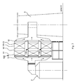
- Figure 1 is a schematic front view showing the structure of a first flue gas treatment device according to an embodiment of the present application
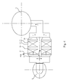
- Figure 2 is a schematic top view showing the structure of the flue gas treatment device shown in Figure 1
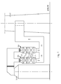
- Figure 3 is a schematic front view showing the structure of a second flue gas treatment device according to an embodiment of the present application
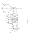
- Figure 4 is a schematic top view showing the structure of the flue gas treatment device shown in Figure 3
- Figure 5 is a schematic front view showing the structure of a third flue gas treatment device according to an embodiment of the present application
- Figure 6 is a schematic top view showing the structure of the flue gas treatment device shown in Figure 5
- Figure 7 is a schematic front view showing the structure of a fourth flue gas treatment device according to an embodiment of the present application
- Figure 8 is a schematic top view showing the structure of the flue gas treatment device shown in Figure 7 .
- a flue gas treatment device 1 is configured to be arranged between a wet desulphurization tower 2 and a stack 3 in a fossil-fuel power plant.
- the flue gas treatment device 1 includes an integrated flue housing 14, a wet electrostatic precipitator 11 and a flue gas heater 13, wherein the integrated flue housing 14 has a flue gas inlet channel 15 configured to communicate with the wet desulphurization tower 2, and a flue gas outlet channel 18 configured to communicate with the stack 3.
- the wet electrostatic precipitator 11 and the flue gas heater 13 are arranged in the integrated flue housing 14 in sequence, the wet electrostatic precipitator 11 is in communication with the flue gas inlet channel 15, the flue gas heater 13 is in communication with the flue gas outlet channel 18, and a first transition flue 16 is formed in the integrated flue housing 14 at a portion between the wet electrostatic precipitator 11 and the flue gas heater 13.
- the flue gas from the wet desulphurization tower 2 firstly passes through the wet electrostatic precipitator 11 in the integrated flue housing 14, to remove most of fine dusts, gypsums, acid mist drips and heavy metals, thereby reducing pollutants to the air. Then, the flue gas is heated by the flue gas heater 13 in the integrated flue housing 14, and finally enters the stack 3 via a flue behind the flue gas integration device to be discharged into the air.
- the flue gas treatment device 1 of the present application since the wet electrostatic precipitator 11 and the flue gas heater 13 are integrated in the integrated flue housing 14, the occupied area of the flue gas treatment device 1 is smaller than that of the solution with devices being arranged separately.
- the flue gas has a good flow uniformity, and further it is not required to arrange a flow equalization orifice plate in the flue, thus the flue gas has a small resistance, thereby reducing the power consumption of the draught fan and increasing the efficiency of the power plant.
- a first flue gas treatment unit 100 is formed by one wet electrostatic precipitator 11 and one flue gas heater 13 which are horizontally arranged.
- One to N groups of the first flue gas treatment units 100 may be provided, wherein the flue gas treatment device 1 in Figures 1 and 2 has one group of the first flue gas treatment unit 100, and the flue gas treatment device 1 in Figures 3 and 4 has six groups of the first flue gas treatment units 100.
- the multiple groups of the first flue gas treatment units 100 are arranged to be overlapped with each other in a vertical height direction or arranged in parallel in a horizontal direction, or arranged in a combined manner of the overlapped arrangement in the vertical height direction and the parallel arrangement in the horizontal direction, and in each group of the first flue gas treatment unit 100, the flue gas inlet channel 15 is in communication with the flue gas outlet channel 18.
- the flue gas treatment device has two groups of the first flue gas treatment units 100 which are horizontally arranged, and each group of the horizontally arranged first flue gas treatment units 100 has three groups of the first flue gas treatment units 100 which are vertically arranged.
- a second flue gas treatment unit 200 is formed by one wet electrostatic precipitator 11 and one flue gas heater 13 which are vertically arranged.
- one to N groups of the second flue gas treatment units 200 may be provided.
- the flue gas treatment device 1 in Figures 5 and 6 has one group of the second flue gas treatment unit 200
- the flue gas treatment device 1 in Figures 7 and 8 has six groups of the second flue gas treatment units 200.
- the multiple groups of the second flue gas treatment units 200 are arranged in parallel in the horizontal direction, and in each group of the second flue gas treatment unit 200, the flue gas inlet channel 15 is in communication with the flue gas outlet channel 18.
- a demister 12 is further provided in the embodiments of the present application, and the demister 12 is arranged between the wet electrostatic precipitator 11 and the flue gas heater 13.
- Figure 9 is a schematic front view showing the structure of a fifth flue gas treatment device according to an embodiment of the present application
- Figure 10 is a schematic top view showing the structure of the flue gas treatment device shown in Figure 9
- Figure 11 is a schematic front view showing the structure of a sixth flue gas treatment device according to an embodiment of the present application
- Figure 12 is a schematic top view showing the structure of the flue gas treatment device shown in Figure 11
- Figure 13 is a schematic front view showing the structure of a seventh flue gas treatment device according to an embodiment of the present application
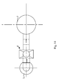
- Figure 14 is a schematic top view showing the structure of the flue gas treatment device shown in Figure 13
- Figure 15 is a schematic front view showing the structure of an eighth flue gas treatment device according to an embodiment of the present application
- Figure 16 a schematic top view showing the structure of the flue gas treatment device shown in Figure 15 .
- a wet electrostatic precipitator 11, a demister 12 and a flue gas heater 13 are arranged in the integrated flue housing 14 in sequence, the wet electrostatic precipitator 11 is in communication with the flue gas inlet channel 15, and the flue gas heater 13 is in communication with the flue gas outlet channel 18.
- a first transition flue 16 is formed in the integrated flue housing 14 at a portion between the wet electrostatic precipitator 11 and the demister 12, and a second transition flue 17 is formed in the integrated flue housing 14 at a portion between the demister 12 and the flue gas heater 3.
- the flue gas from the wet desulphurization tower 2 firstly passes through the wet electrostatic precipitator in the integrated flue housing 14, to remove most of fine dusts, gypsums, acid mist drips and heavy metals, thereby reducing pollutants to the air.
- the flue gas passes through the demister 12 in the integrated flue housing 14 to remove large liquid drops from the wet electrostatic precipitator, thereby reducing the possibility that the acid fog drops may be adhered to the flue gas heater 13, and decreasing corrosion to the device caused in the heating and concentrating process of the acid fog drops; and then the flue gas is heated by the flue gas heater 13 in the integrated flue housing 14, and finally enters the stack 3 via a flue behind the flue gas integration device to be discharged into the air.
- the occupied area of the flue gas treatment device 1 is smaller than that of the solution with devices being arranged separately.
- the flue gas has a good flow uniformity, and further it is not required to arrange a flow equalization orifice plate in the flue, thus the flue gas has a small resistance, thereby reducing the power consumption of the draught fan and increasing the efficiency of the power plant.
- a first flue gas treatment unit 100 is formed by one wet electrostatic precipitator 11, one demister 12 and one flue gas heater 13 which are horizontally arranged.
- One to N groups of the first flue gas treatment units 100 may be provided, wherein the flue gas treatment device 1 in Figures 9 and 10 has one group of the first flue gas treatment unit 100, and the flue gas treatment device 1 in Figures 11 and 12 has six groups of the first flue gas treatment units 100.
- the multiple groups of the first flue gas treatment units 100 are arranged to be overlapped with each other in a vertical height direction or arranged in parallel in a horizontal direction, or arranged in a combined manner of the overlapped arrangement in the vertical height direction and the parallel arrangement in the horizontal direction, and in each group of the first flue gas treatment unit 100, the flue gas inlet channel 15 is in communication with the flue gas outlet channel 18.
- the flue gas treatment device shown in Figures 11 and 12 has two groups of the first flue gas treatment units 100 which are horizontally arranged, and each group of the horizontally arranged first flue gas treatment units 100 has three groups of first flue gas treatment units 100 which are vertically arranged.
- a second flue gas treatment unit 200 is formed by one wet electrostatic precipitator 11, one demister 12 and one flue gas heater 13 which are vertically arranged.
- one to N groups of the second flue gas treatment units 200 may be provided.
- the flue gas treatment device in Figures 13 and 14 has one group of the second flue gas treatment unit 200
- the flue gas treatment device in Figures 15 and 16 has four groups of the second flue gas treatment units 200.
- the multiple groups of the second flue gas treatment units 200 are arranged in parallel in the horizontal direction, and in each group of the second flue gas treatment unit 200, the flue gas inlet channel 15 is in communication with the flue gas outlet channel 18.
- the first transition flue 16 and the second transition flue 17 are both a one-way transition flue 4.
- Figure 17 is a schematic front view showing the structure of a one-way transition flue according to an embodiment of the present application
- Figure 18 is a schematic side view showing the structure of the one-way transition flue shown in Figure 17
- Figure 19 is another schematic side view showing the structure of the one-way transition flue shown in Figure 17
- Figure 20 is a schematic front view showing the structure of another one-way transition flue according to an embodiment of the present application
- Figure 21 is a schematic side view showing the structure of the one-way transition flue shown in Figure 20
- Figure 22 is another schematic side view showing the structure of the one-way transition flue shown in Figure 20 .
- the one-way transition flue 4 includes a large flue section 41 and a small flue section 42, and the large flue section 41 and the small flue section 42 may be arranged in any sequence in the flow direction of the flue gas.
- the one-way transition flue 4 shown in Figure 18 has a quadrangular prism structure, and the section of the one-way transition flue 4 is gradually reduced from four sides of the large flue section 41 to the small flue section 42.
- the one-way transition flue 4 shown in Figure 19 has a quadrangular prism structure, and the section of the one-way transition flue 4 is gradually reduced from two sides of the large flue section 41 to the small flue section 42.
- the one-way transition flue 4 shown in Figure 21 has a quadrangular prism structure, and the section of the one-way transition flue 4 is gradually reduced from three sides of the large flue section 41 to the small flue section 42.
- the one-way transition flue 4 shown in Figure 22 has a quadrangular prism structure, and the section of the one-way transition flue 4 is gradually reduced from one side of the large flue section 41 to the small flue section 42.
- transition flues 4 are merely a few of embodiments, and any transition flue including the large flue section 41 and the small flue section 42 is deemed to fall into the scope of the present application.
Landscapes
- Engineering & Computer Science (AREA)
- Chemical & Material Sciences (AREA)
- Environmental & Geological Engineering (AREA)
- Analytical Chemistry (AREA)
- General Chemical & Material Sciences (AREA)
- Oil, Petroleum & Natural Gas (AREA)
- Chemical Kinetics & Catalysis (AREA)
- Health & Medical Sciences (AREA)
- Biomedical Technology (AREA)
- Treating Waste Gases (AREA)
- Electrostatic Separation (AREA)
- Chimneys And Flues (AREA)
Applications Claiming Priority (1)
| Application Number | Priority Date | Filing Date | Title |
|---|---|---|---|
| CN201310746342.3A CN103697487B (zh) | 2013-12-30 | 2013-12-30 | 一种烟气处理装置 |
Publications (2)
| Publication Number | Publication Date |
|---|---|
| EP2889088A2 true EP2889088A2 (fr) | 2015-07-01 |
| EP2889088A3 EP2889088A3 (fr) | 2016-03-23 |
Family
ID=50359105
Family Applications (1)
| Application Number | Title | Priority Date | Filing Date |
|---|---|---|---|
| EP14181299.0A Withdrawn EP2889088A3 (fr) | 2013-12-30 | 2014-08-18 | Dispositif de traitement de gaz de carneau |
Country Status (5)
| Country | Link |
|---|---|
| US (1) | US9782782B2 (fr) |
| EP (1) | EP2889088A3 (fr) |
| JP (1) | JP6010591B2 (fr) |
| CN (1) | CN103697487B (fr) |
| DE (1) | DE102014111754A1 (fr) |
Cited By (2)
| Publication number | Priority date | Publication date | Assignee | Title |
|---|---|---|---|---|
| CN108704926A (zh) * | 2018-07-04 | 2018-10-26 | 加拿大艾浦莱斯有限公司 | 一种等离子体飞灰熔融处理及金属回收利用系统 |
| CN114353113A (zh) * | 2020-10-13 | 2022-04-15 | 辰衡(上海)环境科技有限公司 | 一种烟气脱白装置及其控制方法 |
Families Citing this family (13)
| Publication number | Priority date | Publication date | Assignee | Title |
|---|---|---|---|---|
| CN104399586B (zh) * | 2014-11-20 | 2017-06-16 | 福建龙净环保股份有限公司 | 一种湿法脱硫系统及其烟气除雾加热装置、电除雾器 |
| CN104832936B (zh) * | 2015-05-08 | 2017-03-08 | 中国能源建设集团广东省电力设计研究院有限公司 | 配单列引风机的除尘器后的设备布置结构及烟气系统 |
| CN104832935B (zh) * | 2015-05-08 | 2017-05-03 | 中国能源建设集团广东省电力设计研究院有限公司 | 配烟气余热回收装置的除尘器后设备布置结构及烟气系统 |
| CN105402762B (zh) * | 2015-12-02 | 2018-06-05 | 中国能源建设集团广东省电力设计研究院有限公司 | 除尘器六出口和双列引风机后烟气系统联合布置结构 |
| CN105444194B (zh) * | 2015-12-10 | 2017-11-17 | 中国能源建设集团广东省电力设计研究院有限公司 | 除尘器二出口和双列引风机后烟气系统联合布置结构 |
| US11179675B2 (en) | 2015-12-22 | 2021-11-23 | Shell Oil Company | Reactor for reducing nitrogen oxides |
| CN108430607A (zh) * | 2015-12-22 | 2018-08-21 | 国际壳牌研究有限公司 | 一种用于减少氮氧化物的催化剂床和方法 |
| CN113893686A (zh) | 2015-12-22 | 2022-01-07 | 国际壳牌研究有限公司 | 催化剂床和用于还原氮氧化物的方法 |
| CN105627341B (zh) * | 2016-03-22 | 2017-10-13 | 中国能源建设集团广东省电力设计研究院有限公司 | 配烟气换热器的除尘器后烟气系统 |
| CN109590112B (zh) * | 2019-01-22 | 2024-10-29 | 国电环境保护研究院有限公司 | 一种相变电除尘系统 |
| CN110523167A (zh) * | 2019-09-05 | 2019-12-03 | 侯俊朋 | 一种地下工程施工用粉尘及酸性气体自动净化过滤设备 |
| CN110860177B (zh) * | 2019-11-27 | 2022-02-22 | 中国石油化工股份有限公司 | 一种烟气净化装置、烟气净化的方法 |
| CN111871612B (zh) * | 2020-08-03 | 2021-05-04 | 山东国舜建设集团有限公司 | 侧出式湿式电除尘器、脱硫脱硝系统、生产线及方法 |
Family Cites Families (36)
| Publication number | Priority date | Publication date | Assignee | Title |
|---|---|---|---|---|
| AR205152A1 (es) * | 1973-02-02 | 1976-04-12 | United States Filter Corp | Precipitador electrostatico humedo |
| US3988127A (en) | 1975-05-07 | 1976-10-26 | John Louis Schumann | Electrostatic precipitator apparatus and method |
| DE2921539C2 (de) | 1979-05-28 | 1985-11-14 | Mannesmann AG, 4000 Düsseldorf | Elektrostaubabscheider-Anordnung |
| WO1984002174A1 (fr) * | 1982-12-01 | 1984-06-07 | Steweag | Procede et installation de rechauffage de gaz de combustion desulfures |
| JPS60156563A (ja) * | 1984-01-26 | 1985-08-16 | Mitsubishi Heavy Ind Ltd | 排ガス処理装置 |
| JPH0691968B2 (ja) | 1986-02-27 | 1994-11-16 | 三菱重工業株式会社 | 排煙処理装置の運転方法 |
| US5282429A (en) * | 1989-08-09 | 1994-02-01 | Chubu Electric Power Company Inc. | Method and system for handling exhaust gas in a boiler |
| DE4034905A1 (de) | 1990-10-31 | 1992-05-07 | Ver Energiewerke Ag | Verfahren zur rauchgasenergieauskopplung an fossil gefeuerten dampfkesseln mit nachgeschalteter rauchgasentschwefelung |
| US5449390A (en) * | 1994-03-08 | 1995-09-12 | Wilhelm Environmental Technologies, Inc. | Flue gas conditioning system using vaporized sulfuric acid |
| US5665142A (en) * | 1994-04-12 | 1997-09-09 | Wilhelm Environmental Technologies, Inc. | Flue gas conditioning system and method using native SO2 feedstock |
| JPH07275652A (ja) | 1994-04-13 | 1995-10-24 | Babcock Hitachi Kk | 一体型排煙浄化装置 |
| US5792238A (en) * | 1995-12-01 | 1998-08-11 | The Babcock & Wilcox Company | Fine-particulate and aerosol removal technique in a condensing heat exchanger using an electrostatic system enhancement |
| US5681375A (en) * | 1996-07-16 | 1997-10-28 | Wilhelm Environmental Technologies, Inc. | Boiler flue gas conditioning system using dilute sulfuric acid injection |
| US5871703A (en) * | 1996-10-09 | 1999-02-16 | Zero Emissions Technology Inc. | Barrier discharge conversion of SO2 and NOx to acids |
| JP3676032B2 (ja) | 1997-04-21 | 2005-07-27 | 三菱重工業株式会社 | 排煙処理設備及び排煙処理方法 |
| US7022296B1 (en) * | 1997-07-10 | 2006-04-04 | University Of Cincinnati | Method for treating flue gas |
| US6863875B1 (en) * | 1998-04-13 | 2005-03-08 | Mitsubishi Heavy Industries, Ltd. | Flue gas treating system and process |
| JP3508827B2 (ja) | 1998-10-01 | 2004-03-22 | 日立プラント建設株式会社 | 排煙処理システム |
| JP2001289430A (ja) | 2000-04-06 | 2001-10-19 | Ishikawajima Harima Heavy Ind Co Ltd | 排ガス処理装置 |
| JP2001327830A (ja) | 2000-05-22 | 2001-11-27 | Ishikawajima Harima Heavy Ind Co Ltd | 排煙処理装置 |
| EP1174172A3 (fr) | 2000-07-19 | 2003-02-05 | Emil A.J. D.I. Wieser-Linhart | Procédé et dispositif pour purification d'un gaz |
| DE10048516B4 (de) * | 2000-09-29 | 2006-01-05 | Fritz Curtius | Vorrichtung für Wärme- und Stoff-Austauschvorgänge |
| JP2002136835A (ja) * | 2000-11-01 | 2002-05-14 | Babcock Hitachi Kk | 二室型湿式排煙脱硫装置 |
| JP4841065B2 (ja) * | 2001-06-21 | 2011-12-21 | 三菱重工メカトロシステムズ株式会社 | 排煙のso3分除去装置 |
| US7814742B2 (en) * | 2006-12-13 | 2010-10-19 | Mitsubishi Heavy Industries, Ltd. | Integrated coal gasification combined cycle plant |
| JP2008200561A (ja) * | 2007-02-16 | 2008-09-04 | Hitachi Plant Technologies Ltd | 硫黄酸化物を含む排ガスの処理方法 |
| JP5384799B2 (ja) * | 2007-03-30 | 2014-01-08 | 三菱重工メカトロシステムズ株式会社 | 排ガス処理装置および排ガス処理方法 |
| CN201105202Y (zh) * | 2007-09-14 | 2008-08-27 | 东南大学 | 烟气湿法脱硫中协同脱除细颗粒的装置 |
| JP4853737B2 (ja) | 2008-02-22 | 2012-01-11 | 株式会社日立プラントテクノロジー | 排ガス処理方法及び装置 |
| CN101251262B (zh) * | 2008-03-27 | 2011-06-22 | 张宏博 | 锅炉多级吸入湿法脱硫脱氮除尘工艺方法 |
| JP5281858B2 (ja) * | 2008-09-22 | 2013-09-04 | バブコック日立株式会社 | 排ガス処理装置 |
| JP5705443B2 (ja) | 2010-03-02 | 2015-04-22 | 三菱重工業株式会社 | 仕上げ排煙脱硫装置及びこれを用いた排ガス処理システム |
| JP5335740B2 (ja) * | 2010-08-03 | 2013-11-06 | 株式会社日立製作所 | 排ガスの処理方法及び設備 |
| US9289720B2 (en) * | 2012-05-31 | 2016-03-22 | Mitsubishi Hitachi Power Systems, Ltd. | System and method for treating mercury in flue gas |
| CN102941011A (zh) * | 2012-11-26 | 2013-02-27 | 广东依科电力技术有限公司 | 一种喷淋脱硫塔及其工作方法 |
| CN203718811U (zh) * | 2013-12-30 | 2014-07-16 | 上海克莱德贝尔格曼机械有限公司 | 一种烟气处理装置 |
-
2013
- 2013-12-30 CN CN201310746342.3A patent/CN103697487B/zh active Active
-
2014
- 2014-08-18 DE DE102014111754.9A patent/DE102014111754A1/de not_active Withdrawn
- 2014-08-18 EP EP14181299.0A patent/EP2889088A3/fr not_active Withdrawn
- 2014-09-10 US US14/482,891 patent/US9782782B2/en not_active Expired - Fee Related
- 2014-09-26 JP JP2014196074A patent/JP6010591B2/ja not_active Expired - Fee Related
Non-Patent Citations (1)
| Title |
|---|
| None |
Cited By (2)
| Publication number | Priority date | Publication date | Assignee | Title |
|---|---|---|---|---|
| CN108704926A (zh) * | 2018-07-04 | 2018-10-26 | 加拿大艾浦莱斯有限公司 | 一种等离子体飞灰熔融处理及金属回收利用系统 |
| CN114353113A (zh) * | 2020-10-13 | 2022-04-15 | 辰衡(上海)环境科技有限公司 | 一种烟气脱白装置及其控制方法 |
Also Published As
| Publication number | Publication date |
|---|---|
| CN103697487B (zh) | 2016-05-11 |
| US9782782B2 (en) | 2017-10-10 |
| CN103697487A (zh) | 2014-04-02 |
| DE102014111754A1 (de) | 2015-07-02 |
| EP2889088A3 (fr) | 2016-03-23 |
| US20150182974A1 (en) | 2015-07-02 |
| JP2015127046A (ja) | 2015-07-09 |
| JP6010591B2 (ja) | 2016-10-19 |
Similar Documents
| Publication | Publication Date | Title |
|---|---|---|
| EP2889088A2 (fr) | Dispositif de traitement de gaz de carneau | |
| US12072096B2 (en) | Method and system for improving boiler effectiveness | |
| CN106512637B (zh) | 一种消除白烟的装置和方法 | |
| CN103303877B (zh) | 多气源低浓度so2烟气综合回收制酸工艺流程 | |
| CN105413442A (zh) | 立式脱硫塔 | |
| CN108554158A (zh) | 一种高温高湿烟气降温脱硫净化系统 | |
| CN204494452U (zh) | 一种具有高密封性能的火电厂脱硫系统 | |
| CN201930707U (zh) | 烟气脱硫装置 | |
| CN103521047A (zh) | 一种提高烧结脱硫烟气排放温度的方法及其系统 | |
| CN203718811U (zh) | 一种烟气处理装置 | |
| CN104190228B (zh) | 一种复合高效节能氨法脱硫塔 | |
| CN202380048U (zh) | 用于铝带加热与支撑的装置 | |
| CN106064016A (zh) | 废气脱硫脱硝超净除尘一体化装置 | |
| CN204815978U (zh) | 安装于脱硫塔的除尘除雾器 | |
| CN204853524U (zh) | 一种脱硫除尘设备 | |
| CN203750406U (zh) | 一种顺流塔-逆流塔串联烟气脱硫装置 | |
| CN204034551U (zh) | 一种烟气脱硫设备 | |
| CN204107259U (zh) | 一种小型炉窑多功能烟尘治理装置 | |
| CN103157372B (zh) | 一种均尘紊流循环流化床烟气脱硫装置 | |
| CN203556285U (zh) | 气液湍流型脱硫除尘器 | |
| CN105536495A (zh) | 一种侧出式脱硫塔 | |
| CN101874976A (zh) | 基于湿法脱硫塔补充空气增强低负荷适应性能的脱硫方法 | |
| CN107321157A (zh) | 一种卧式湿法脱硫装置 | |
| CN209138282U (zh) | 一种功能导向产物分区的氨法脱硫氧化循环槽装置 | |
| CN206075155U (zh) | 一种用于大气污染物处理设备的自循环调节装置 |
Legal Events
| Date | Code | Title | Description |
|---|---|---|---|
| PUAI | Public reference made under article 153(3) epc to a published international application that has entered the european phase |
Free format text: ORIGINAL CODE: 0009012 |
|
| 17P | Request for examination filed |
Effective date: 20140818 |
|
| AK | Designated contracting states |
Kind code of ref document: A2 Designated state(s): AL AT BE BG CH CY CZ DE DK EE ES FI FR GB GR HR HU IE IS IT LI LT LU LV MC MK MT NL NO PL PT RO RS SE SI SK SM TR |
|
| AX | Request for extension of the european patent |
Extension state: BA ME |
|
| PUAL | Search report despatched |
Free format text: ORIGINAL CODE: 0009013 |
|
| RIC1 | Information provided on ipc code assigned before grant |
Ipc: B01D 53/50 20060101ALI20160210BHEP Ipc: B01D 53/32 20060101ALN20160210BHEP Ipc: B03C 3/02 20060101ALN20160210BHEP Ipc: F23J 15/02 20060101ALI20160210BHEP Ipc: B03C 3/16 20060101AFI20160210BHEP Ipc: B03C 3/017 20060101ALI20160210BHEP Ipc: B03C 3/019 20060101ALI20160210BHEP Ipc: B03C 3/82 20060101ALI20160210BHEP Ipc: F23J 15/08 20060101ALI20160210BHEP |
|
| AK | Designated contracting states |
Kind code of ref document: A3 Designated state(s): AL AT BE BG CH CY CZ DE DK EE ES FI FR GB GR HR HU IE IS IT LI LT LU LV MC MK MT NL NO PL PT RO RS SE SI SK SM TR |
|
| AX | Request for extension of the european patent |
Extension state: BA ME |
|
| RBV | Designated contracting states (corrected) |
Designated state(s): AL AT BE BG CH CY CZ DE DK EE ES FI FR GB GR HR HU IE IS IT LI LT LU LV MC MK MT NL NO PL PT RO RS SE SI SK SM TR |
|
| STAA | Information on the status of an ep patent application or granted ep patent |
Free format text: STATUS: THE APPLICATION HAS BEEN WITHDRAWN |
|
| 18W | Application withdrawn |
Effective date: 20170822 |