EP2889124A1 - Imprimante tridimensionnelle et son procédé de commande - Google Patents
Imprimante tridimensionnelle et son procédé de commande Download PDFInfo
- Publication number
- EP2889124A1 EP2889124A1 EP14195508.8A EP14195508A EP2889124A1 EP 2889124 A1 EP2889124 A1 EP 2889124A1 EP 14195508 A EP14195508 A EP 14195508A EP 2889124 A1 EP2889124 A1 EP 2889124A1
- Authority
- EP
- European Patent Office
- Prior art keywords
- areas
- layer
- ink
- solidified
- adjacent
- Prior art date
- Legal status (The legal status is an assumption and is not a legal conclusion. Google has not performed a legal analysis and makes no representation as to the accuracy of the status listed.)
- Withdrawn
Links
Images






Classifications
-
- B—PERFORMING OPERATIONS; TRANSPORTING
- B29—WORKING OF PLASTICS; WORKING OF SUBSTANCES IN A PLASTIC STATE IN GENERAL
- B29C—SHAPING OR JOINING OF PLASTICS; SHAPING OF MATERIAL IN A PLASTIC STATE, NOT OTHERWISE PROVIDED FOR; AFTER-TREATMENT OF THE SHAPED PRODUCTS, e.g. REPAIRING
- B29C67/00—Shaping techniques not covered by groups B29C39/00 - B29C65/00, B29C70/00 or B29C73/00
-
- B—PERFORMING OPERATIONS; TRANSPORTING
- B33—ADDITIVE MANUFACTURING TECHNOLOGY
- B33Y—ADDITIVE MANUFACTURING, i.e. MANUFACTURING OF THREE-DIMENSIONAL [3D] OBJECTS BY ADDITIVE DEPOSITION, ADDITIVE AGGLOMERATION OR ADDITIVE LAYERING, e.g. BY 3D PRINTING, STEREOLITHOGRAPHY OR SELECTIVE LASER SINTERING
- B33Y30/00—Apparatus for additive manufacturing; Details thereof or accessories therefor
-
- B—PERFORMING OPERATIONS; TRANSPORTING
- B29—WORKING OF PLASTICS; WORKING OF SUBSTANCES IN A PLASTIC STATE IN GENERAL
- B29C—SHAPING OR JOINING OF PLASTICS; SHAPING OF MATERIAL IN A PLASTIC STATE, NOT OTHERWISE PROVIDED FOR; AFTER-TREATMENT OF THE SHAPED PRODUCTS, e.g. REPAIRING
- B29C64/00—Additive manufacturing, i.e. manufacturing of three-dimensional [3D] objects by additive deposition, additive agglomeration or additive layering, e.g. by 3D printing, stereolithography or selective laser sintering
- B29C64/10—Processes of additive manufacturing
- B29C64/106—Processes of additive manufacturing using only liquids or viscous materials, e.g. depositing a continuous bead of viscous material
- B29C64/112—Processes of additive manufacturing using only liquids or viscous materials, e.g. depositing a continuous bead of viscous material using individual droplets, e.g. from jetting heads
-
- B—PERFORMING OPERATIONS; TRANSPORTING
- B29—WORKING OF PLASTICS; WORKING OF SUBSTANCES IN A PLASTIC STATE IN GENERAL
- B29C—SHAPING OR JOINING OF PLASTICS; SHAPING OF MATERIAL IN A PLASTIC STATE, NOT OTHERWISE PROVIDED FOR; AFTER-TREATMENT OF THE SHAPED PRODUCTS, e.g. REPAIRING
- B29C64/00—Additive manufacturing, i.e. manufacturing of three-dimensional [3D] objects by additive deposition, additive agglomeration or additive layering, e.g. by 3D printing, stereolithography or selective laser sintering
- B29C64/30—Auxiliary operations or equipment
- B29C64/386—Data acquisition or data processing for additive manufacturing
- B29C64/393—Data acquisition or data processing for additive manufacturing for controlling or regulating additive manufacturing processes
-
- B—PERFORMING OPERATIONS; TRANSPORTING
- B33—ADDITIVE MANUFACTURING TECHNOLOGY
- B33Y—ADDITIVE MANUFACTURING, i.e. MANUFACTURING OF THREE-DIMENSIONAL [3D] OBJECTS BY ADDITIVE DEPOSITION, ADDITIVE AGGLOMERATION OR ADDITIVE LAYERING, e.g. BY 3D PRINTING, STEREOLITHOGRAPHY OR SELECTIVE LASER SINTERING
- B33Y10/00—Processes of additive manufacturing
-
- B—PERFORMING OPERATIONS; TRANSPORTING
- B29—WORKING OF PLASTICS; WORKING OF SUBSTANCES IN A PLASTIC STATE IN GENERAL
- B29K—INDEXING SCHEME ASSOCIATED WITH SUBCLASSES B29B, B29C OR B29D, RELATING TO MOULDING MATERIALS OR TO MATERIALS FOR MOULDS, REINFORCEMENTS, FILLERS OR PREFORMED PARTS, e.g. INSERTS
- B29K2101/00—Use of unspecified macromolecular compounds as moulding material
-
- B—PERFORMING OPERATIONS; TRANSPORTING
- B29—WORKING OF PLASTICS; WORKING OF SUBSTANCES IN A PLASTIC STATE IN GENERAL
- B29L—INDEXING SCHEME ASSOCIATED WITH SUBCLASS B29C, RELATING TO PARTICULAR ARTICLES
- B29L2009/00—Layered products
-
- H—ELECTRICITY
- H04—ELECTRIC COMMUNICATION TECHNIQUE
- H04N—PICTORIAL COMMUNICATION, e.g. TELEVISION
- H04N1/00—Scanning, transmission or reproduction of documents or the like, e.g. facsimile transmission; Details thereof
- H04N1/46—Colour picture communication systems
- H04N1/52—Circuits or arrangements for halftone screening
Definitions
- the following description relates to a three dimensional printer and control method thereof.
- Ink jetting a type of three dimensional (3D) printing process of building up an object, has two types: binder jetting and material jetting.
- the binder jetting is a process of spraying binder and color pigments onto a material in powdered form, and implementing 3D color printing by combining the material with color pigments.
- steps of spraying and solidifying ink are involved in the material jetting process.
- a color ink is sprayed near another color ink having not yet been solidified, unintended color likely results due to blending of the colors.
- separate processes of spraying and solidifying ink may inevitably increase the processing time.
- the following description relates to a three dimensional (3D) printer for spraying and solidifying liquid ink to build a 3D object to prevent implementation of unintended color due to a mix of different color ink and increase 3D printing speed by enhancing the process of spraying and solidifying the ink.
- a control method of the 3D printer for building a 3D object by laminating a plurality of layers includes forming first areas not adjacent to each other in one of the plurality of layers and solidifying the first areas; and forming second areas not adjacent to each other in the layer between the solidified first areas and solidifying the second areas.
- Each of the first area and the second area may include at least one cell, which is a minimum sized picture element implemented by the 3D printer.
- Each of the first area and the second area may include at least one block that includes a plurality of cells.
- the areas not adjacent to each other may have borders of a predetermined size shared with neighboring areas.
- a control method of a three dimensional (3D) printer for building a 3D object by laminating a plurality of layers includes forming one of the plurality of layers, wherein the layer is formed by spraying ink of a designated color onto first areas not adjacent to each other; solidifying the ink sprayed onto the first area; spraying ink of a designated color onto second areas not adjacent to each other between the first areas; and solidifying the ink sprayed onto the second areas.
- Each of the first area and the second area may include at least one cell, which is a minimum sized picture element implemented by the 3D printer.
- Each of the first area and the second area may include at least one block that includes a plurality of cells.
- the areas not adjacent to each other may have borders of a predetermined size shared with neighboring areas.
- a control method of a three dimensional (3D) printer for building a 3D object by laminating a plurality of layers wherein the plurality of layers includes a preceding layer and a subsequent layer laminated on the preceding layer.
- the control method includes forming first areas not adjacent to each other in the preceding layer and solidifying the first areas; and forming second areas not adjacent to each other in the preceding layer between the solidified first areas, and forming first areas not adjacent to each other in the subsequent layer on top of the solidified first areas of the preceding.
- the control method may further include solidifying the second areas of the preceding layer together with the first areas of the subsequent layer.
- Each of the first area and the second area may include at least one cell, which is a minimum sized picture element implemented by the 3D printer.
- Each of the first area and the second area may include at least one block that includes a plurality of cells.
- the areas not adjacent to each other may have borders of a predetermined size shared with neighboring areas.
- a control method of a three dimensional (3D) printer for building a 3D object by laminating a plurality of layers includes forming a neighboring first layer and second layer of the plurality of layers, wherein the neighboring first layer and second layer of the plurality of layers are formed by spraying ink of a designated color onto first areas not adjacent to each other in the first layer; solidifying the ink sprayed onto the first areas in the first layer; spraying ink of a designated color onto second areas not adjacent to each other between the first areas of the first layer, and spraying ink of a designated color onto the solidified first areas of the first layer to form first areas not adjacent to each other in the second layer; solidifying the ink sprayed onto the second areas of the first layer and the ink sprayed onto the first areas of the second layer; spraying ink of a designated color onto second areas not adjacent to each other between the first areas of the second layer; and solidifying the ink sprayed onto the second areas of the second layer.
- Each of the first area and the second area may include at least one cell, which is a minimum sized picture element implemented by the 3D printer.
- Each of the first area and the second area may include at least one block that includes a plurality of cells.
- the areas not adjacent to each other may have borders of a predetermined size shared with neighboring areas.
- Each of the first area and the second area may include at least one cell, which is a minimum sized picture element implemented by the 3D printer.
- Each of the first area and the second area may include at least one block that includes a plurality of cells.
- the light source may include an ultraviolet (UV) light source.
- UV ultraviolet
- the areas not adjacent to each other have borders of a predetermined size shared with neighboring areas.
- the controller may control the second areas of the preceding layer and the first areas of the subsequent layer to be solidified together.
- Each of the first area and the second area may include at least one cell, which is a minimum sized picture element implemented by the 3D printer.
- Each of the first area and the second area may include at least one block that includes a plurality of cells.
- the light source may include an ultraviolet (UV) light source.
- UV ultraviolet
- the areas not adjacent to each other have borders of a predetermined size shared with neighboring areas.
- a three dimensional (3D) printer as set out in claim 7.
- Preferred features are set out in claims 2 to 12.
- a three dimensional (3D) printer that sprays and solidifies liquid ink to build a 3D object prevents implementation of unintended color due to a mix of different color ink, and increases 3D printing speed by enhancing the process of spraying and solidifying the ink.
- first, second, third, etc. may be used herein to describe various elements, components, regions, layers and/or sections, these elements, components, regions, layers and/or sections should not be limited by these terms. These terms are only used to distinguish one element, component, region, layer or section from another region, layer or section. Thus, a first element, component, region, layer or section discussed below could be termed a second element, component, region, layer or section without departing from the teachings of the present disclosure.
- the terminology used herein is for the purpose of describing particular embodiments only and is not intended to be limiting of the invention. It is to be understood that the singular forms "a,” “an,” and “the” include plural references unless the context clearly dictates otherwise.
- FIG. 1 is a perspective view of a three dimensional (3D) printer, according to an embodiment of the present disclosure. Illustrated in particular is an internal structure of a 3D printer 100 according to an embodiment of the present disclosure, which may further be equipped with a case for defining the appearance of the 3D printer 100 and protecting the internal devices.
- the 3D printer 100 is divided into a main body 102 and a bracket 152. Additionally, the 3D printer 100 may further include a main board mounted with a controller 202 for controlling general 3D printing operations and peripheral circuits, a power supply for supplying power, an input unit 204 for generating input signals corresponding to user manipulation, and a display 210, such as a Liquid Crystal Display (LCD), which will be described in detail in connection with FIG. 2 .
- LCD Liquid Crystal Display
- the main body 102 includes an ink supplier (or ink container) 104, a maintenance station 106, and a two dimensional (2D) stage 108.
- the ink container 104 is loaded with a great amount of ink of various colors: cyan, magenta, yellow and black, each ink color supplied to an inkjet head 158 through a corresponding ink supply tube 162.
- Ink may be a liquid (resin) from melted photo curing plastic.
- the maintenance station 106 is where the inkjet head 158 regularly/irregularly moves into for maintenance/repair. If the inkjet head 158 moves into the maintenance station 106, cleaning work for the inkjet head 158 is performed.
- the 2D stage 108 is where the 3D printing job is performed, and moves back and forth along yz-axis as represented in FIG. 1 .
- the bracket 152 includes a transfer unit 154 and a guide rail 156.
- the inkjet head 158 and a light source 160 are equipped in the transfer unit 154 and move with the transfer unit 154.
- the inkjet head 158 is also equipped with a number of ink nozzles through which drops of ink of different colors are sprayed in the ink jetting process.
- the ink container 104 and the inkjet head 158 are connected to each other through the ink supply tubes 162. Ink drops are supplied from the ink container 104 to the inkjet head 158 through the ink supply tubes 162.
- Ink (or resin) sprayed as a photo curing material from the inkjet head 158 is solidified when exposed to light (e.g., ultraviolet (UV)).
- UV ultraviolet
- the UV light source 160 illuminates ink with light, solidifying the ink sprayed from the inkjet head 158 by having the ink exposed to light. If the ink sprayed from the inkjet head 158 is not the photo curing material, but rather a thermoset material, the light source 160 may be replaced by a heat source that radiates heat.
- the transfer unit 154 equipped with the inkjet head 158 and the light source 160 moves back and forth along the guide rail 156 on the x-axis represented in FIG. 1 . While the transfer unit 154 is moving along the guide rail 156, the inkjet head 158 may spray drops of ink onto the 2D stage 108 and the light source 160 may illuminate the ink sprayed onto the 2D stage 108 with light. With 3D movement (on the xyz-axis) of the transfer unit 154 and the 2D stage 108, a product of 3D printing may be produced on the 2D stage 108.
- FIG. 2 is a block diagram illustrating a control system of a 3D printer, according to an embodiment of the present disclosure. As shown in FIG. 2 , input ends of a controller 202 for controlling overall operations of the 3D printer 100 are operatively and electrically coupled with an input unit 204, a data converter 206, and a memory 208.
- Output ends of the controller 202 are operatively and electrically coupled with the transfer unit 154, the inkjet head 158, the light source 160, the 2D stage 108, the maintenance station 106, and a display 210.
- the input unit 204 At the input end of the controller 202, the input unit 204 generates input signals corresponding to user manipulation.
- the data converter 206 converts printing data into a format available to the controller 202.
- the printing data may be generated by the 3D printer 100 itself, or may be input to the 3D printer 100 from outside of the 3D printer 100 through a communication line. Further, an external storage device, such as a Universal Serial Bus (USB) memory, an external hard disk, or the like may send the printing data to the 3D printer 100.
- the memory 208 stores the received printing data, or stores software programs for the controller 202 to control overall operations of the 3D printer 100.
- the transfer unit 154, the inkjet head 158, the light source 160, the 2D stage 108, and the maintenance station 106 at the output end of the controller 202 were described above in connection with FIG. 1 .
- the display 210 displays operating status information and user setting information of the 3D printer 100.
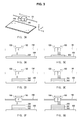
- FIGS. 3A-3G illustrate 3D printing operations of a 3D printer, according to an embodiment of the present disclosure.
- FIG. 3A only illustrates the inkjet head 158 and the light source 160 that move back and forth along the guide rail 156 on the x-axis, and the 2D stage 108, from the 3D printer 100 shown in FIG. 1 .
- FIGS. 3B to 3G illustrate what is shown in FIG. 3A as viewed along the y-axis.
- FIGS. 3B to 3G illustrate a process of building a 3D object by performing 3D printing in the 3D printer 100, according to an embodiment of the present disclosure.
- the embodiment is not limited to this movement.
- the guide rail 156 may move along the y-axis
- the 2D stage 108 may move along the z-axis.
- a product from the 3D printing 3D movement of the inkjet head 158 and light source 160 relative to the 2D stage 108 in the xyz-axis direction is required.
- the controller 202 moves the 2D stage 108 upward on the z-axis to make the 2D stage 108 approach the inkjet head 158. While doing this, the controller 202 controls the inkjet head 158 to spray ink (resin) onto a top surface of the 2D stage 108 to form a first layer 302.
- the width and thickness of an area into which ink is sprayed from the inkjet head 158 to form the first layer 302 is determined from printing data input to the controller 202. In other words, ink is sprayed such an extent as to satisfy the width and thickness of the first layer 302 among the plurality of layers to form an intended object.
- the thickness of a single layer depends on a resolution (precision) to be attained for the intended object.
- the thickness of a layer may be from approximately 0.01mm to approximately 0.08mm, for example.
- the controller 202 controls the light source 160 to illuminate the first layer 302 with UV, as shown in FIG. 3C .
- the first layer 302 is solidified.
- the UV illumination may take from approximately 0.3 seconds to approximately 1 second, depending on the thickness of a layer.
- non-solidified and solidified layers are distinguished by representing them in white (not shaded) and by shading, respectively. Throughout the following description, non-solidified and solidified layers will also be distinguished by representing them in white (not shaded) and by shading, respectively.
- the controller 202 controls the inkjet head 158 to spray drops of ink (resin) onto the top surface of the solidified first layer to form a second layer 304.
- the width and thickness of an area into which ink is sprayed from the inkjet head 158 to form the second layer 304 is determined from printing data input to the controller 202. In other words, ink is sprayed to such an extent as to meet the width and thickness of the second layer 302 among a plurality of layers to form the intended object.
- the 2D stage 108 may be moved downward along the z-axis as much as the thickness of the second layer 304.
- the controller 202 controls the light source 160 to illuminate the second layer 304 with UV, as shown in FIG. 3E . With the UV illumination with the light source 160, the second layer 304 is solidified.
- the controller 202 controls the inkjet head 158 to spray drops of ink (resin) onto the top surface of the solidified second layer to form a third layer 306.
- the width and thickness of an area into which ink is sprayed from the inkjet head 158 to form the third layer 306 is determined from printing data input to the controller 202. In other words, ink is sprayed such an extent as to meet the width and thickness of the third layer 306 among the plurality of layers to form the intended object.
- the 2D stage 108 may be moved downward along the z-axis as much as the thickness of the third layer 306.
- the controller 202 controls the light source 160 to illuminate the third layer 306 with UV, as shown in FIG. 3G . With the UV illumination with the light source 160, the third layer 306 is solidified.
- one of a plurality of ink colors e.g., cyan, magenta, yellow, and black loaded in the ink container 104 may be selectively sprayed to form the object in that color.
- a medium ink color may be implemented by combining the plurality of ink colors of cyan, magenta, yellow, and black.
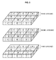
- FIG. 4 illustrates an object implemented by a 3D printer, according to an embodiment of the present disclosure.
- FIG. 5 illustrates an exploded view of the object shown in FIG. 4 , which shows individual layers separately. How to form individual layers of the object of FIG. 4 may be explained as shown in FIG. 5 .
- An object 400 shown in FIGS. 4 and 5 may include three layers: a first layer 402, a second layer 404, and a third layer 406.
- the first layer 402, the second layer 404, and the third layer 406 each have a plurality of areas (cells or blocks) in different colors.
- the term 'cell' refers to a picture element, such as pixel of a 2D image or voxel of a 3D image, which may have a minimum size that may be implemented by the 3D printer 100 in accordance with an embodiment of the present disclosure.
- the term 'block' refers to a set of a plurality of neighboring cells in a single color. As shown in FIGS. 4 and 5 , areas represented by C, M, and Y refer to cyan, magenta, and yellow colored areas, respectively. The respective areas may have different colors implemented in combination of cyan, magenta, yellow, and black colors.
- FIGS. 6 to 8 illustrate a control method of a 3D printer, according to an embodiment of the present disclosure.
- the embodiment relates to a method for building the object shown in FIGS. 4 and 5 by using 3D printing.
- multiple areas are combined to form an object.
- the method as illustrated in FIGS. 6 to 8 may also be applied to embodiments for combining multiple blocks to form an object.
- the control method of the 3D printer in accordance with the embodiment of the present disclosure is characterized by forming first areas not adjacent to each other in one of a plurality of layers and solidifying the first areas, spraying drops of ink between the solidified first areas to form second areas not adjacent to each other in the same layer, and solidifying the second areas, thereby avoiding unintended color blending in the border between neighboring areas in different colors not yet solidified.
- the term 'neighboring areas' refer to areas that share a part of their borders in which unintended color implementation due to color blending may be a matter of concern.
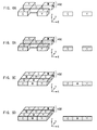
- FIGS. 6A-6D illustrate a process of generating the first layer 402 of the object shown in FIGS. 4 and 5 .
- the controller 202 controls the inkjet head 158 to spray ink to form areas not adjacent to each other in the first layer 402 with nine areas arranged in a 3x3 format.
- areas in cyan C, yellow Y, and magenta M colors are formed with the sprayed ink.
- the controller 202 controls the light source 160 to UV illuminate the ink sprayed as shown in FIG. 6A for solidification, as shown in FIG. 6B . Shaded areas of FIG. 6B represent solidified areas.
- the controller 202 then controls the inkjet head 158 to spray ink between the solidified areas not adjacent to each other in the first layer 402 to form remaining areas of the first layer 402, as shown in FIG. 6C .
- FIG. 6C since new areas are formed by spraying ink between the solidified areas (represented as shaded areas), even if the solidified areas and the new non-solidified areas are adjacent to each other, unintended color blending in the border of those areas may not occur.
- the controller 202 controls the light source 160 to UV illuminate the new areas for solidification, as shown in FIG. 6D .
- the first layer 402 is completely formed through the successive procedures as shown in FIGS. 6A to 6D .
- FIGS. 7A-7D illustrate a process of generating the second layer 404 of the object shown in FIGS. 4 and 5 .
- the controller 202 controls the inkjet head 158 to spray ink onto the solidified first layer 402 to form areas not adjacent to each other in the second layer 404 with nine areas arranged in a 3x3 format.
- areas in cyan C, yellow Y, and magenta M colors are formed with the sprayed ink.
- color blending may not occur in the border between the areas because the areas are not adjacent to each other.
- the controller 202 controls the light source 160 to UV illuminate the ink sprayed as shown in FIG. 7A for solidification, as shown in FIG. 7B . Shaded areas of FIG. 7B represent solidified areas.
- the controller 202 then controls the inkjet head 158 to spray ink between the solidified areas not adjacent to each other in the second layer 404 to form remaining areas of the second layer 404, as shown in FIG. 7C .
- FIG. 7C since new areas are formed by spraying ink between the solidified areas (represented as shaded areas), even if the solidified areas and the new non-solidified areas are adjacent to each other, unintended color blending in the border between those areas may not occur.
- the controller 202 controls the light source 160 to UV illuminate the new areas for solidification, as shown in FIG. 7D .
- the second layer 404 is completely formed through the successive procedures as shown in FIGS. 7A to 7D .
- FIGS. 8A-8D illustrate a process of generating the third layer 406 of the object shown in FIGS. 4 and 5 .
- the controller 202 controls the inkjet head 158 to spray ink onto the solidified second layer 404 solidified to form areas not adjacent to each other in the third layer 406 with nine areas arranged in a 3x3 format.
- areas in cyan C, yellow Y, and magenta M colors are formed with the sprayed ink.
- the controller 202 controls the light source 160 to UV illuminate the ink sprayed as shown in FIG. 8A for solidification, as shown in FIG. 8B . Shaded areas of FIG. 8B represent solidified areas.
- the controller 202 then controls the inkjet head 158 to spray ink between the solidified areas not adjacent to each other in the third layer 406 to form remaining areas of the third layer 406, as shown in FIG. 8C .
- FIG. 8C since new areas are formed by spraying ink between the solidified areas (represented as shaded areas), even if the solidified areas and the new non-solidified areas are adjacent to each other, unintended color blending in the border of those areas may not occur.
- the controller 202 controls the light source 160 to UV illuminate the new areas for solifidication, as shown in FIG. 8D .
- the third layer 406 is completely formed through successive procedures as shown in FIGS. 8A to 8D .
- FIGS. 9 to 11 illustrate a control method of a 3D printer, according to an embodiment of the present disclosure.
- the embodiment relates to a method for building the object shown in FIGS. 4 and 5 by using 3D printing.
- multiple areas are combined to form the object.
- the method as illustrated in FIGS. 9 to 11 may also be applied to embodiments for combining multiple blocks to form an object.
- the control method of the 3D printer in accordance with the embodiment of the present disclosure is characterized by forming first areas not adjacent to each other in a preceding layer and solidifying the first areas, spraying drops of ink between the solidified first areas to form second areas not adjacent to each other in the same layer, and solidifying the second areas, thereby avoiding unintended color blending in the border between neighboring areas in different ink colors not yet solidified, wherein ink spraying for generating first areas not adjacent to each other in the subsequent layer and ink spraying for generating the second areas of the preceding layer are performed at a time, thereby increasing the printing speed as well.
- the term 'neighboring areas' refer to areas that share a part of their borders in which unintended color implementation due to color blending may be a matter of concern. If the shared part of the borders of the neighboring areas is so small that such color blending there need not be concerned about, the areas are not deemed to be adjacent to each other.
- areas with non-solidified ink are represented in white while areas with solidified ink are represented with shading.
- FIGS. 9A-9D illustrate a process of generating the first layer 402 of the object shown in FIGS. 4 and 5 .
- the controller 202 controls the inkjet head 158 to spray ink to form areas not adjacent to each other in the first layer 402 with nine areas arranged in a 3x3 format.
- areas in cyan C, yellow Y, and magenta M colors are formed with the sprayed ink.
- the controller 202 controls the light source 160 to UV illuminate the ink sprayed as shown in FIG. 9A for solidification, as shown in FIG. 9B . Shaded areas of FIG. 9B represent solidified areas.
- the controller 202 then controls the inkjet head 158 to spray ink between the solidified areas not adjacent to each other in the first layer 402 to form remaining areas of the first layer 402, as shown in FIG. 9C , and simultaneously, controls the inkjet head 158 to spray ink onto the areas already solidified in the first layer 402 to form some areas for the second layer 404.
- ink spraying for forming the remaining areas of the first layer 402 and for forming some areas not adjacent to each other in the second layer 404 with nine areas arranged in a 3x3 format is performed at a same time.
- FIG. 9C since new areas are formed by spraying ink between the solidified areas (represented as shaded areas), even if the solidified areas and the new non-solidified areas are adjacent to each other, unintended color blending in the border of those areas may not occur.
- the controller 202 controls the light source 160 to UV illuminate the new areas for solidification, as shown in FIG. 9D .
- the first layer 402 is completely formed through the successive procedures as shown in FIGS. 9A to 9D . Comparing the process shown in FIGS. 9A to 9D with that of FIGS. 6A to 6D , it can be seen that the former case (of FIGS. 9A to 9D ) takes only four steps to form the first layer 402 as well as some areas of the second layer 404 and solidify them, but the latter case (of FIGS. 6A to 6D ) takes four steps only to form the first layer 402.
- carrying out ink spraying at a same time for forming some areas of the first layer 402 and some areas of the second layer 404 may significantly reduce the time spent on forming the areas of the first layer 402 and the areas of the second layer 404, compared with a case of separately carrying out ink spraying for forming the areas of the first layer 402 and the areas of the second area 404.
- carrying out UV illumination at a same time for solidifying some areas of the first layer 402 and some areas of the second layer 404 may significantly reduce the time spent on light illumination to solidify the areas of the first layer 402 and the areas of the second layer 404, compared with a case of separately carrying out light illumination to solidify the areas of the first layer 402 and the areas of the second area 404.
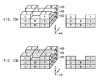
- FIGS. 10A and 10B illustrate a process of generating the second layer 404 of the object shown in FIGS. 4 and 5 .
- the controller 202 controls the inkjet head 158 to spray ink between the solidified areas not adjacent to each other to form remaining areas of the second layer 404 with nine areas arranged in a 3x3 format and to form new areas not adjacent to each other in the third layer 406 (see non-solidified areas in FIG. 10A ).
- ink spraying for forming the remaining areas of the second layer 404 and for forming some areas not adjacent to each other in the third layer 406 with nine areas arranged in a 3x3 format is performed at a same time.
- FIG. 10A the controller 202 controls the inkjet head 158 to spray ink between the solidified areas not adjacent to each other to form remaining areas of the second layer 404 with nine areas arranged in a 3x3 format and to form new areas not adjacent to each other in the third layer 406 (see non-solidified areas in FIG. 10A ).
- the controller 202 controls the light source 160 to UV illuminate the ink sprayed as shown in FIG. 10A for solidification, as shown in FIG. 10B .
- Shaded areas of FIG. 10B represent solidified areas.
- the second layer 404 is completely formed through the successive procedures as shown in FIGS. 10A and 10B . Comparing the process illustrated in FIGS. 10A and 10B with that of FIGS. 7A to 7D , it can be seen that the former case (of FIGS. 10A and 10B ) takes two steps to form some areas of the second layer 404 as well as the third layer 406 and solidify them, but the latter case (of FIGS. 7A to 7D ) takes four steps to form the second layer 404.
- carrying out ink spraying at a same time for forming some areas of the second layer 404 and for forming some areas of the third layer 406 may significantly reduce the time spent on forming the areas of the second layer 404 and the areas of the third layer 406, compared with a case of separately carrying out ink spraying for forming the areas of the second layer 404 and for forming the areas of the third area 406.
- carrying out UV illumination at a same time for solidifying some areas of the second layer 404 and for solidifying some areas of the third layer 406 may significantly reduce the time spent on light illumination to solidify the areas of the second layer 404 and the areas of the third layer 406, compared with a case of significantly carrying out light illumination to solidify the areas of the second layer 404 and the areas of the third area 404.
- FIGS. 11A and 11B illustrate a process of generating the third layer 406 of the object shown in FIGS. 4 and 5 .
- the controller 202 controls the inkjet head 158 to spray ink between solidified areas not adjacent to each other to form remaining areas of the third layer 406 with nine areas arranged in a 3x3 format (see non-solidified areas in FIG. 11A ).
- areas in cyan C, yellow Y, and magenta M colors are formed with the sprayed ink.
- color blending may not occur in the border between the areas of the third layer 406 because the areas are not adjacent to each other.
- the areas formed not to be adjacent to each other in the lower second layer 404 has already been solidified, color blending in the border between areas of the second layer 404 and third layer 406 may not occur.
- the controller 202 controls the light source 160 to UV illuminate the ink sprayed as shown in FIG. 11A for solidification, as shown in FIG. 11 B . Shaded areas of FIG. 11B represent solidified areas.
- the third layer 406 is completely formed through the successive procedures as shown in FIGS. 11A and 11B . Comparing the process illustrated in FIGS. 11A and 11B with that of FIGS. 8A to 8D , it can be seen that the former case (of FIGS. 11A and 11B ) takes two steps to form the third layer 406, but the latter case (of FIGS. 8A to 8D ) takes four steps to form the third layer 406.
- carrying out ink spraying at a same time for forming some areas of the second layer 404 and for forming some areas of the third layer 406 may significantly reduce the time spent on forming the areas of the second layer 404 and the areas of the third layer 406, compared with a case of separately carrying out ink spraying for forming the areas of the second layer 404 and for forming the areas of the third area 406.
- carrying out UV illumination at a same time for solidifying some areas of the second layer 404 and for solidifying some areas of the third layer 406 may significantly reduce the time spent on light illumination to solidify the areas of the second layer 404 and the areas of the third layer 406, compared with a case of significantly carrying out light illumination to solidify the areas of the second layer 404 and the areas of the third area 404.
- embodiments of the invention can provide a control method of a three dimensional (3D) printer for building a 3D object, the control method comprising: forming first areas not adjacent to each other and solidifying the first areas; and forming second areas adjacent to the solidified first areas, and solidifying the second areas.
- the method further comprises laminating a first layer and a second layer laminated on the first layer; forming the first areas not adjacent to each other in the first layer and solidifying the first areas; and forming second areas adjacent to the solidified first areas in the first layer, and forming first areas in the second layer on top of the solidified first areas of the first layer.
- Embodiments of the invention can also provide a three dimensional (3D) printer for building a 3D object, the 3D printer comprising: an inkjet head equipped with multiple nozzles for spraying ink; a light source for solidifying the sprayed ink; a stage on which an object is formed with the ink sprayed from the inkjet head; and a controller for performing 3D printing based on printing data, wherein the controller is arranged to form first areas not adjacent to each other and to solidify the first areas; and to form second areas adjacent to the solidified first areas and solidify the second areas.
- 3D printer comprising: an inkjet head equipped with multiple nozzles for spraying ink; a light source for solidifying the sprayed ink; a stage on which an object is formed with the ink sprayed from the inkjet head; and a controller for performing 3D printing based on printing data, wherein the controller is arranged to form first areas not adjacent to each other and to solidify the first areas; and to form second areas adjacent to
- the controller is arranged to form the first areas not adjacent to each other in a first layer and to solidify the first areas, and to form second areas adjacent to the solidified first areas in the first layer and to form first areas in a second layer on top of the solidified first areas of the first layer.
- the above-described embodiments may be recorded in computer-readable media including program instructions to implement various operations embodied by a computer.
- the media may also include, alone or in combination with the program instructions, data files, data structures, and the like.
- the program instructions recorded on the media may be those specially designed and constructed for the purposes of embodiments, or they may be of the kind well-known and available to those having skill in the computer software arts.
- Examples of computer-readable media include magnetic media such as hard disks, floppy disks, and magnetic tape; optical media such as CD ROM disks and DVDs; magneto-optical media such as optical disks; and hardware devices that are specially configured to store and perform program instructions, such as read-only memory (ROM), random access memory (RAM), flash memory, and the like.
- the computer-readable media may also be a distributed network, so that the program instructions are stored and executed in a distributed fashion.
- the program instructions may be executed by one or more processors.
- the computer-readable media may also be embodied in at least one application specific integrated circuit (ASIC) or Field Programmable Gate Array (FPGA), which executes (processes like a processor) program instructions. Examples of program instructions include both machine code, such as produced by a compiler, and files containing higher level code that may be executed by the computer using an interpreter.
- the above-described devices may be configured to act as one or more software modules in order to perform the operations of the above-described embodiments, or vice versa.
Landscapes
- Engineering & Computer Science (AREA)
- Chemical & Material Sciences (AREA)
- Materials Engineering (AREA)
- Manufacturing & Machinery (AREA)
- Mechanical Engineering (AREA)
- Physics & Mathematics (AREA)
- Optics & Photonics (AREA)
Applications Claiming Priority (1)
| Application Number | Priority Date | Filing Date | Title |
|---|---|---|---|
| KR1020130169141A KR20150079119A (ko) | 2013-12-31 | 2013-12-31 | 3차원 프린터 및 그 제어 방법 |
Publications (1)
| Publication Number | Publication Date |
|---|---|
| EP2889124A1 true EP2889124A1 (fr) | 2015-07-01 |
Family
ID=52015869
Family Applications (1)
| Application Number | Title | Priority Date | Filing Date |
|---|---|---|---|
| EP14195508.8A Withdrawn EP2889124A1 (fr) | 2013-12-31 | 2014-11-28 | Imprimante tridimensionnelle et son procédé de commande |
Country Status (3)
| Country | Link |
|---|---|
| US (1) | US20150183162A1 (fr) |
| EP (1) | EP2889124A1 (fr) |
| KR (1) | KR20150079119A (fr) |
Cited By (4)
| Publication number | Priority date | Publication date | Assignee | Title |
|---|---|---|---|---|
| EP3254828A1 (fr) * | 2016-06-10 | 2017-12-13 | OCE Holding B.V. | Système et méthode d'impression pour objet avec un motif en surface |
| CN109195472A (zh) * | 2016-05-31 | 2019-01-11 | 耐克创新有限合伙公司 | 梯度打印三维结构部件 |
| KR20200004929A (ko) * | 2017-04-20 | 2020-01-15 | 엑스와이지프린팅, 인크. | 입체 인쇄 장치 |
| USD926236S1 (en) * | 2020-04-28 | 2021-07-27 | Revotek Co., Ltd | Instrument for preparing bio-ink |
Families Citing this family (12)
| Publication number | Priority date | Publication date | Assignee | Title |
|---|---|---|---|---|
| JP6461488B2 (ja) * | 2014-05-21 | 2019-01-30 | 株式会社ミマキエンジニアリング | 三次元構造物を形成する形成装置 |
| JP6396723B2 (ja) * | 2014-08-25 | 2018-09-26 | 株式会社ミマキエンジニアリング | 液滴吐出装置及び液滴吐出方法 |
| JP2016054276A (ja) * | 2014-09-04 | 2016-04-14 | 株式会社東芝 | 半導体装置の製造方法 |
| US10800153B2 (en) * | 2014-11-20 | 2020-10-13 | Hewlett-Packard Development Company, L.P. | Generating three-dimensional objects |
| US11220042B2 (en) * | 2015-02-04 | 2022-01-11 | Ohio State Innovation Foundation | Systems and methods for additive manufacturing |
| CN107199699B (zh) * | 2016-03-18 | 2020-02-04 | 三纬国际立体列印科技股份有限公司 | 彩色三维模型的切层打印方法 |
| JP2018043441A (ja) * | 2016-09-15 | 2018-03-22 | セイコーエプソン株式会社 | 三次元造形装置、三次元造形方法、および、コンピュータープログラム |
| WO2020065657A2 (fr) | 2018-09-27 | 2020-04-02 | Stratasys Ltd. | Procédé et système de fabrication additive à l'aide d'une commande de température en boucle fermée |
| US11179927B2 (en) | 2018-12-21 | 2021-11-23 | Icon Technology, Inc. | Systems and methods for the construction of structures utilizing additive manufacturing techniques |
| EP3898145B1 (fr) * | 2018-12-21 | 2024-07-24 | Icon Technology, Inc. | Systèmes et procédés de construction de structures mettant en oeuvre des techniques de fabrication additive |
| JP7446794B2 (ja) * | 2019-11-29 | 2024-03-11 | キヤノン株式会社 | 三次元造形物の製造方法、および三次元造形装置 |
| CN117916039A (zh) * | 2021-09-14 | 2024-04-19 | 深圳帧观德芯科技有限公司 | 具有空隙填充的3d(三维)打印 |
Citations (3)
| Publication number | Priority date | Publication date | Assignee | Title |
|---|---|---|---|---|
| EP1522412A1 (fr) * | 2003-10-07 | 2005-04-13 | Fujifilm Electronic Imaging Limited | Formation d'une couche ou structure superficielle sur un substrat |
| EP2447045A2 (fr) * | 2010-11-01 | 2012-05-02 | Keyence Corporation | Procédé de formage tridimensionnel et appareil de formage tridimensionnel |
| US20120133080A1 (en) * | 2010-11-29 | 2012-05-31 | 3D Systems, Inc. | Additive Manufacturing Methods for Improved Curl Control and Sidewall Quality |
Family Cites Families (5)
| Publication number | Priority date | Publication date | Assignee | Title |
|---|---|---|---|---|
| GB2233928B (en) * | 1989-05-23 | 1992-12-23 | Brother Ind Ltd | Apparatus and method for forming three-dimensional article |
| US7300619B2 (en) * | 2000-03-13 | 2007-11-27 | Objet Geometries Ltd. | Compositions and methods for use in three dimensional model printing |
| JP3805266B2 (ja) * | 2002-02-27 | 2006-08-02 | Uht株式会社 | セラミック積層体の製造装置 |
| CN106881856B (zh) * | 2010-04-25 | 2020-01-24 | 斯特塔西有限公司 | 带外壳物体的实体无模制造 |
| JP5724317B2 (ja) * | 2010-11-18 | 2015-05-27 | ソニー株式会社 | 3次元造形装置 |
-
2013
- 2013-12-31 KR KR1020130169141A patent/KR20150079119A/ko not_active Withdrawn
-
2014
- 2014-07-22 US US14/337,556 patent/US20150183162A1/en not_active Abandoned
- 2014-11-28 EP EP14195508.8A patent/EP2889124A1/fr not_active Withdrawn
Patent Citations (3)
| Publication number | Priority date | Publication date | Assignee | Title |
|---|---|---|---|---|
| EP1522412A1 (fr) * | 2003-10-07 | 2005-04-13 | Fujifilm Electronic Imaging Limited | Formation d'une couche ou structure superficielle sur un substrat |
| EP2447045A2 (fr) * | 2010-11-01 | 2012-05-02 | Keyence Corporation | Procédé de formage tridimensionnel et appareil de formage tridimensionnel |
| US20120133080A1 (en) * | 2010-11-29 | 2012-05-31 | 3D Systems, Inc. | Additive Manufacturing Methods for Improved Curl Control and Sidewall Quality |
Cited By (5)
| Publication number | Priority date | Publication date | Assignee | Title |
|---|---|---|---|---|
| CN109195472A (zh) * | 2016-05-31 | 2019-01-11 | 耐克创新有限合伙公司 | 梯度打印三维结构部件 |
| US11618206B2 (en) | 2016-05-31 | 2023-04-04 | Nike, Inc. | Gradient printing a three-dimensional structural component |
| EP3254828A1 (fr) * | 2016-06-10 | 2017-12-13 | OCE Holding B.V. | Système et méthode d'impression pour objet avec un motif en surface |
| KR20200004929A (ko) * | 2017-04-20 | 2020-01-15 | 엑스와이지프린팅, 인크. | 입체 인쇄 장치 |
| USD926236S1 (en) * | 2020-04-28 | 2021-07-27 | Revotek Co., Ltd | Instrument for preparing bio-ink |
Also Published As
| Publication number | Publication date |
|---|---|
| US20150183162A1 (en) | 2015-07-02 |
| KR20150079119A (ko) | 2015-07-08 |
Similar Documents
| Publication | Publication Date | Title |
|---|---|---|
| EP2889124A1 (fr) | Imprimante tridimensionnelle et son procédé de commande | |
| CN104309309B (zh) | 一种图像喷绘打印方法及打印装置 | |
| EP3221137B1 (fr) | Impression texturée multicouche | |
| US20220266523A1 (en) | System and method for additive manufacturing of an object | |
| US10029440B2 (en) | Method and apparatus for fabricating three-dimensional object and recording medium | |
| TWI674978B (zh) | 彩色立體列印方法與立體列印設備 | |
| JP5615667B2 (ja) | 三次元造形装置用の設定データ作成装置、三次元造形装置用の設定データ作成方法及び三次元造形装置用の設定データ作成プログラム並びにコンピュータで読み取り可能な記録媒体 | |
| US9446558B2 (en) | Three-dimensional printing apparatus and printing head module | |
| US20150251358A1 (en) | Three dimensional printing apparatus and method for controlling printing head thereof | |
| Mao et al. | Multi-material stereolithography using curing-on-demand printheads | |
| CN104284770A (zh) | 打印三维结构体的方法,控制打印头和打印制品的方法 | |
| CN108927989A (zh) | 立体打印方法 | |
| CN203198407U (zh) | 一种3d数码印刷机 | |
| CN110007585B (zh) | 用于在钟表部件上制造功能性元件的方法 | |
| CN113829626A (zh) | 多作业三维打印方法、设备、存储介质和软件程序产品 | |
| KR101628164B1 (ko) | 블록 적층 방식과 수지압출 기술을 결합한 3d 프린팅 시스템 및 하이브리드 3d 프린팅을 위한 설계 데이터 생성 방법 | |
| JP6768588B2 (ja) | 多色3dオブジェクトのスライスプリント方法 | |
| EP3539774B1 (fr) | Appareil et procédé de fabrication tridimensionnelle | |
| US8746872B2 (en) | Method for UV inkjet printer to generate irregular transparent matte particle surface and completed printing object thereof | |
| JP2006098929A (ja) | 表示媒体の製造装置、表示媒体の製造方法、および表示媒体 | |
| US20180257304A1 (en) | Fabrication management system and fabrication management control apparatus | |
| TWI680886B (zh) | 三維列印裝置 | |
| KR20180123788A (ko) | 잉크젯 헤드 유닛을 구비하는 인쇄 장치를 사용하는 인쇄 방법 | |
| JP2016204905A (ja) | 出隅部材 | |
| CN103317873A (zh) | Uv喷墨打印机生成不规则式透明雾面颗粒表面的方法及其完成的打印物 |
Legal Events
| Date | Code | Title | Description |
|---|---|---|---|
| PUAI | Public reference made under article 153(3) epc to a published international application that has entered the european phase |
Free format text: ORIGINAL CODE: 0009012 |
|
| 17P | Request for examination filed |
Effective date: 20141128 |
|
| AK | Designated contracting states |
Kind code of ref document: A1 Designated state(s): AL AT BE BG CH CY CZ DE DK EE ES FI FR GB GR HR HU IE IS IT LI LT LU LV MC MK MT NL NO PL PT RO RS SE SI SK SM TR |
|
| AX | Request for extension of the european patent |
Extension state: BA ME |
|
| R17P | Request for examination filed (corrected) |
Effective date: 20151216 |
|
| RBV | Designated contracting states (corrected) |
Designated state(s): AL AT BE BG CH CY CZ DE DK EE ES FI FR GB GR HR HU IE IS IT LI LT LU LV MC MK MT NL NO PL PT RO RS SE SI SK SM TR |
|
| STAA | Information on the status of an ep patent application or granted ep patent |
Free format text: STATUS: EXAMINATION IS IN PROGRESS |
|
| 17Q | First examination report despatched |
Effective date: 20170522 |
|
| STAA | Information on the status of an ep patent application or granted ep patent |
Free format text: STATUS: THE APPLICATION IS DEEMED TO BE WITHDRAWN |
|
| 18D | Application deemed to be withdrawn |
Effective date: 20190319 |