EP2889164A2 - Compresseur pour un pneumatique autogonflant - Google Patents
Compresseur pour un pneumatique autogonflant Download PDFInfo
- Publication number
- EP2889164A2 EP2889164A2 EP14195995.7A EP14195995A EP2889164A2 EP 2889164 A2 EP2889164 A2 EP 2889164A2 EP 14195995 A EP14195995 A EP 14195995A EP 2889164 A2 EP2889164 A2 EP 2889164A2
- Authority
- EP
- European Patent Office
- Prior art keywords
- compression
- piston
- compressor
- tire
- blind hole
- Prior art date
- Legal status (The legal status is an assumption and is not a legal conclusion. Google has not performed a legal analysis and makes no representation as to the accuracy of the status listed.)
- Withdrawn
Links
- 230000006835 compression Effects 0.000 claims abstract description 148
- 238000007906 compression Methods 0.000 claims abstract description 148
- 239000012530 fluid Substances 0.000 claims abstract description 88
- 238000004891 communication Methods 0.000 claims abstract description 37
- 238000013016 damping Methods 0.000 claims description 11
- 230000006837 decompression Effects 0.000 claims description 4
- 239000011324 bead Substances 0.000 description 6
- 125000004122 cyclic group Chemical group 0.000 description 4
- 238000000034 method Methods 0.000 description 4
- 230000000737 periodic effect Effects 0.000 description 3
- 238000005086 pumping Methods 0.000 description 3
- 238000007789 sealing Methods 0.000 description 3
- 239000007787 solid Substances 0.000 description 3
- 230000007423 decrease Effects 0.000 description 2
- 238000005096 rolling process Methods 0.000 description 2
- 229910052782 aluminium Inorganic materials 0.000 description 1
- XAGFODPZIPBFFR-UHFFFAOYSA-N aluminium Chemical compound [Al] XAGFODPZIPBFFR-UHFFFAOYSA-N 0.000 description 1
- 238000005452 bending Methods 0.000 description 1
- 230000008602 contraction Effects 0.000 description 1
- 230000001419 dependent effect Effects 0.000 description 1
- 239000013536 elastomeric material Substances 0.000 description 1
- 238000003780 insertion Methods 0.000 description 1
- 230000037431 insertion Effects 0.000 description 1
- 238000004519 manufacturing process Methods 0.000 description 1
- 239000000463 material Substances 0.000 description 1
- 229910052751 metal Inorganic materials 0.000 description 1
- 239000002184 metal Substances 0.000 description 1
- 230000037361 pathway Effects 0.000 description 1
- 230000002572 peristaltic effect Effects 0.000 description 1
- 239000004033 plastic Substances 0.000 description 1
- 229920003023 plastic Polymers 0.000 description 1
- 230000036316 preload Effects 0.000 description 1
- 230000003746 surface roughness Effects 0.000 description 1
- XLYOFNOQVPJJNP-UHFFFAOYSA-N water Substances O XLYOFNOQVPJJNP-UHFFFAOYSA-N 0.000 description 1
Images


Classifications
-
- B—PERFORMING OPERATIONS; TRANSPORTING
- B60—VEHICLES IN GENERAL
- B60C—VEHICLE TYRES; TYRE INFLATION; TYRE CHANGING; CONNECTING VALVES TO INFLATABLE ELASTIC BODIES IN GENERAL; DEVICES OR ARRANGEMENTS RELATED TO TYRES
- B60C23/00—Devices for measuring, signalling, controlling, or distributing tyre pressure or temperature, specially adapted for mounting on vehicles; Arrangement of tyre inflating devices on vehicles, e.g. of pumps or of tanks; Tyre cooling arrangements
- B60C23/10—Arrangement of tyre-inflating pumps mounted on vehicles
- B60C23/12—Arrangement of tyre-inflating pumps mounted on vehicles operated by a running wheel
- B60C23/121—Arrangement of tyre-inflating pumps mounted on vehicles operated by a running wheel the pumps being mounted on the tyres
-
- B—PERFORMING OPERATIONS; TRANSPORTING
- B60—VEHICLES IN GENERAL
- B60C—VEHICLE TYRES; TYRE INFLATION; TYRE CHANGING; CONNECTING VALVES TO INFLATABLE ELASTIC BODIES IN GENERAL; DEVICES OR ARRANGEMENTS RELATED TO TYRES
- B60C29/00—Arrangements of tyre-inflating valves to tyres or rims; Accessories for tyre-inflating valves, not otherwise provided for
-
- F—MECHANICAL ENGINEERING; LIGHTING; HEATING; WEAPONS; BLASTING
- F04—POSITIVE - DISPLACEMENT MACHINES FOR LIQUIDS; PUMPS FOR LIQUIDS OR ELASTIC FLUIDS
- F04B—POSITIVE-DISPLACEMENT MACHINES FOR LIQUIDS; PUMPS
- F04B9/00—Piston machines or pumps characterised by the driving or driven means to or from their working members
- F04B9/02—Piston machines or pumps characterised by the driving or driven means to or from their working members the means being mechanical
Definitions
- the invention relates to a compressor mountable in an annular tire cavity for inflating a pneumatic tire.
- the invention relates also to a pneumatic tire comprising a compressor according to the invention.
- the invention may also relate to a tire assembly comprising a compressor and at least one of a rim, a tire, and a hydraulic actuator for driving the compressor.
- tires may be provided with self-inflating tires.
- Such tires shall be able to maintain a desired tire cavity pressure in an autonomous manner.
- such tires may comprise pumps actuated by the tire's periodical deformation when the tire is rolling over the ground, wherein the pumps may compress air from the environment and expel it into the tire cavity.
- US-A2012/0160386 discloses a self inflating tire comprising a pump assembly and a compression actuator assembly.
- the pump assembly comprises a main body with an axial chamber in which two pistons reciprocate. They delimit a compression room that translates when the pistons reciprocate.
- the first piston is activated by the compression actuator assembly.
- the second piston comprises a shaft that engages the first piston in a cavity.
- leaks may occur at the interface between the cavity and the shaft, and may thus reduce the pump's efficiency and yield.
- the yield of the pump relies on the surface roughness of the cavity and the shaft. Consequently, production costs may be elevated, all the more so due to the pump's small size for insertion through the thickness of the tire's sidewall.
- the maximal pressure the pump may provide is also limited.
- Another object of the present invention may consist in improving the efficiency of a compressor for inflating a tire.
- a further object of the invention may consist in increasing the maximal pressure provided by a compressor.
- the invention relates to a compressor in accordance with claim 1 and to a tire assembly in accordance with claim 14.
- a compressor mountable in an annular tire cavity as for instance to the tire's sidewall.
- the compressor comprises an air inlet, an air outlet, and a body in which are formed a blind hole having a sidewall, and a compression chamber in fluid communication with the air inlet and the air outlet.
- the compressor comprises a compression piston configured for reciprocating in the compression chamber for providing compressed air to the tire cavity through the air outlet, and a hydraulic fluid passage for providing hydraulic fluid into the blind hole, as well as a guiding piston or rod configured for reciprocating in the blind hole in sealed contact with the sidewall and for guiding a reciprocating movement of the body relative to the compression piston.
- the body may comprisey a wall tightly separating the compression chamber and the blind hole.
- the compression piston and the guiding piston mat extend in parallel directions such that the body is moved relatively and in parallel to the compression piston and the guiding piston upon actuation by hydraulic fluid pressure provided to the blind hole.
- the compression piston and the guiding piston are rigidly fixed relative to each other, and the body is movable relatively to the compression piston and the guiding piston.
- the compressor may comprise a support to be mounted to the tire, the compression piston and the guiding piston being rigidly fixed to the support and the body being moveable in relation to the support.
- the support may be mounted to the tire or the tire's sidewall by a screwed or glued connection.
- the compression piston may extend in the compression chamber along or over a longer portion than the guiding piston may extend in the blind hole.
- the body may be arranged and configured to move between a compression state and a decompression or intake state relative to the compression piston.
- the compressor may comprises two damping plates disposed at opposing faces of the body in relation to the direction of the reciprocating movement to damp the body abutting the support when reciprocating between the compression state and the decompressed state.
- the compression piston and the guiding piston may be movable along two different parallel axes offset from each other.
- the body may comprise an inlet chamber and a pipe in fluid communication with the air inlet and being configured for reciprocating in the inlet chamber.
- the pipe may have an elongated shape, elongated in parallel to the direction of reciprocating movement of the guiding piston and/or of the compression piston. Further, the pipe may have two opposed ends and may comprise a through hole connecting both ends.
- the inlet chamber and the compression chamber may be in fluid communication through a passageway.
- the compression chamber may have a shape of a bore with a bottom, a sidewall and an opening, wherein the passageway forms an aperture on the sidewall which is remotely disposed from the bottom or disposed between the bottom and the opening.
- the body may be arranged and configured to move between a compression state and a decompression or intake state relative to the compression piston, wherein the pipe may be elongated in respect of the direction of reciprocating movement and may comprise a through hole connecting its two axially opposed faces.
- the inlet chamber and the compression chamber may be in fluid communication through a passageway, wherein in the decompression state, the passageway is in fluid communication with the compression chamber, and in the compression state, the compression piston blocks fluid communication between the passageway and the compression chamber.
- the compression piston may comprise a through hole connecting its two axially opposite faces or ends, and, optionally, a check valve in fluid communication with the through hole.
- the volume of the through hole of the compression piston is inferior to the half of the maximal free volume in the compression chamber during the compression piston's reciprocating movement.
- the compressor may comprise a spring opposing or biasing a compression movement of the compression piston within the compression chamber.
- the compression piston and the guiding piston and/or the blind hole and the compression chamber may cover the majority of the body in respect of the direction of the reciprocating movement.
- the hydraulic fluid passage may be formed in the guiding piston and may connect two axially opposite faces of the guiding piston.
- the hydraulic fluid passage may be formed in the body.
- the guiding piston may be configured for reciprocating in the blind hole in sealed contact with the sidewall and for guiding a reciprocating movement of the body relative to the compression piston upon cyclically or periodically providing hydraulic fluid or hydraulic fluid pressure to the blind hole via the hydraulic fluid passage.
- Hydraulic fluid or fluid pressure may be cyclically or periodically provided to the hydraulic fluid passage via a hydraulic actuator.
- Such an actuator or engine may be driven by the cyclical or periodic deformation of the tire's sidewall or another portion of the tire periodically deforming when the tire is rolling.
- the support may be a frame which may have a plurality of rigid struts.
- the volume of the through hole of the compression piston may be inferior to the tenth of the maximal free volume of the compression chamber available during the compression piston's reciprocating movement.
- the body may be fixed to the tire and the support may be movable relative to the tire and the body.
- the tire assembly comprises a tire having a tire cavity and the aforementioned compressor.
- the tire assembly may comprise an actuating mechanism or hydraulic actuator in hydraulic fluid communication with the blind hole.
- the tire comprises a sidewall with the compressor being mounted inside the tire cavity to the sidewall.
- the through hole of the compression piston is in fluid communication with the annular tire cavity of the tire assembly.
- the assembly may further comprise a pipe or tube connecting the air inlet of the compressor with a through hole in the tire's sidewall for allowing fluid communication of the air inlet with the tire's (outer) environment.
- the hydraulic actuator or pump may be mounted on the tire, and the compressor may be mounted on the rim.
- the actuator and the compressor may be connected via a tube for conducting hydraulic fluid.
- the hydraulic actuator may comprise a flexible or deformable bag or reservoir for holding a hydraulic fluid.
- the bag may be mounted to the tire's sidewall and may be deformed by the cyclical or periodical deflection of the sidewall upon the tire's rotation.
- the body may be subject to tire cavity pressure or in direct fluid communication with the tire cavity.
- a method for inflating or pumping air into a tire via a compressor is disclosed.
- the method comprises the step of periodically or cyclically providing hydraulic fluid or hydraulic fluid pressure to the compressor, in particular to the blind hole, via the hydraulic fluid passage.
- the method may comprise the step of periodically or cyclically providing hydraulic fluid or hydraulic fluid pressure to the compressor, in particular to the blind hole, via the hydraulic fluid passage by means of a hydraulic actuator.
- the method may comprise the step of periodically or cyclically providing hydraulic fluid or hydraulic fluid pressure to the compressor, in particular to the blind hole, via the hydraulic fluid passage by means of a hydraulic actuator driven by the periodic or cyclic rotation of the tire.
- the actuator or engine may be mounted to the tire's sidewall deflecting or deforming upon rotation of the tire.
- the actuator may comprise a flexible hydraulic fluid reservoir or bag cyclically or periodically deforming upon rotation of the tire.
- the reservoir may have an opening and/or nozzle in fluid communication with the compressor's hydraulic fluid passage, as for instance via a tube.
- Axial and “axially” mean lines or directions that are parallel to the axis of rotation of the tire.
- “Circumferential” means lines or directions extending along the perimeter of the surface of the annular tread perpendicular to the axial direction.
- Periodaltic means operating by means of wave-like contractions that propel contained matter, such as air, along tubular pathways.
- Ring and radially mean directions radially toward or away from the axis of rotation of the tire.
- “Sidewall” means that portion of a tire between the tread and the bead.
- Figure 1 represents a perspective view of a tire assembly 2 according to a first embodiment of the invention.
- the tire assembly 2 comprises a tire 4 with a carcass (not shown), a tread portion 6 having an annular shape, two lateral sidewalls 8 and two annular beads 10 at the radially inner extremity of each sidewall 8.
- Each sidewall 8 has an annular shape with a central opening delimited by one of the beads 10.
- the tire 4 defines an annular cavity 12 which is delimited by its tread portion 6, its sidewalls 8 and eventually its beads 10.
- the tire assembly 2 also comprises a compressor 14 for injecting or pumping compressed air into the annular cavity of the tire 4.
- the compressor 14 is mounted in the annular cavity 12. Preferably, it is mounted on a sidewall 8.
- the compressor 14 may be activated by the cyclic deformation of the tire 4 and/or the tire's sidewall 8 against the ground when it runs.
- the tire assembly 2 may form a self-inflating tire assembly.
- the compressor 14 may be activated by an actuating mechanism (not represented), as for instance by a hydraulic actuator or pump.
- the actuator may be mounted on a rim, on a hub, or on the tire 4, wherein the actuator may provide a hydraulic fluid, whose hydraulic pressure fluctuates upon rotation of the tire assembly 2.
- the hydraulic fluid may be an incompressible fluid as for instance water or oil.
- a hydraulic actuator is for example known from US-A-2012/0160386 which provides an actuating medium for actuating a compressor by means of the bending of the tire's sidewall 8.
- US-A-2012/0160386 which provides an actuating medium for actuating a compressor by means of the bending of the tire's sidewall 8.
- Figure 2 represents an axial view of a tire assembly 3 according to another embodiment of the invention, wherein elements equal to those already shown in Figure 1 are described by equal reference numerals.
- the tire assembly 3 may comprise a rim 16 on which is mounted the tire 4.
- the tire assembly 3 may be a wheel which may be mounted on a vehicle.
- the rim 16 may have a circular shape, with a disc portion 18 and an annular portion surrounding the disc portion 18.
- the disc portion 18 may comprise a central hole 22 which may be mounted on a hub of a vehicle. It may also comprise a set of fixing holes 24.
- the annular portion may comprise two annular flanges 26 which extend in a radial outer direction and which are disposed at each axial extremity of the rim 16.
- the beads 10 of the tire 4 are in contact with the annular flanges 26 of the annular portion and the flanges 26 are arranged for axially retaining the tire 4, particularly its beads 10.
- the annular cavity 12 of the tire 4 is closed by the rim 16, eventually by its cylindrical portion.
- the tire assembly 3 may comprise a valve (not represented) for inflating the tire 4 by known means.
- a tire assembly 3 may comprise a compressor 14 arranged within the tire cavity (not visible in the plan view of Figure 2 ).
- Figure 3 represents an air compressor 14 according to an embodiment of the invention, in which the compressor is represented in a decompressed or, in other words, in an intake state.
- the air compressor 14 comprises an air inlet 28 and an air outlet 30.
- the air inlet 28 is in fluid communication with the tire's environment, which may be substantially at the atmospheric pressure.
- the air inlet 28 may comprise or may be connected to a channel which passes through a sidewall 8. The provision of such a channel is known in the prior art and is for instance disclosed in US 8,156,978 B1 which is also incorporated herein by reference.
- the air outlet 30 is in fluid communication with the annular cavity of the tire which may be at the inflating pressure.
- the compressor 14 preferably comprises a support 32 which may be a frame.
- the support 32 may form a hollow box or enclosure, which may have one or more open sides.
- the support 32 may have an elongated shape which may extend in a longitudinal direction and which may comprise a mounting plate 34 which may be in contact with the sidewall 8 when the compressor 14 is mounted on the tire.
- the mounting plate 34 may be adapted to the shape of the inner surface of the sidewall 8 at its mounting position.
- the support 32 may comprise two essentially parallel plates 36 extending perpendicularly from the main plate 34 and perpendicular to the elongated shape. In other words, the plates 36 may extend in a direction perpendicular or transversal to the longitudinal direction.
- the compressor 14, or especially the support 32 may comprise fixation means like holes or seats 38 for mounting the compressor 14 via screws to the tire.
- the fixation means may be provided on the mounting plate 34.
- the compressor 14 further comprises a body 40 disposed between the parallel plates 36 or, in other words, within the frame.
- the body 40 forms a block of material and is movable along the longitudinal direction of the elongated support 32, for instance along a straight line.
- the body 40 may reciprocate relative to the support 32 in order to provide compressed fluid.
- the body may be fixed to the tire and the support may be movable relative to the tire and the body 40.
- the body 40 comprises a compression chamber 42, an inlet chamber 44, and a blind hole 46.
- the compression chamber 42 is in fluid communication with the air outlet 30 and also with the inlet chamber 44 of the compressor 14.
- Each chamber and the blind hole 46 may form a bore or blind bore extending into the body 40.
- Each bore may have a cylindrical shape and/or a bottom, an opening and a sidewall extending between them.
- the chambers and the blind hole 46 may extend in parallel directions.
- the body 40 may have an elongated shape and two ends, wherein a first half of the body extends from the first end, essentially in parallel to the body's elongated shape and comprises at least a major part of the compression chamber 42.
- a second half of the body 40 extends, essentially in parallel to the body's elongated shape, from the second end and comprises at least a major part of the inlet chamber 44, if any, as well as at least a major part of the blind hole 46.
- the chambers and the blind hole 46 extend essentially in parallel to the body's or the support's elongated shape or, in other words, in parallel to the longitudinal direction.
- the compression chamber 42 may overlap with the inlet chamber 44 and/or the blind hole 46 with respect to the longitudinal direction. However, both chambers 42, 44 are tightly separated from each other.
- the openings of the inlet chamber 44 and of the blind hole 46 are preferably provided at a face of the body 40 opposite to the face of the body 40 comprising the opening of the compression
- the inlet chamber 44 and the compression chamber 42 are in fluid communication with each other, preferably through a passageway 48, wherein the passageway 48 may extend from the bottom of the inlet chamber 44 to the sidewall of the compression chamber 42 and may form an aperture 50 on the compression chamber's sidewall.
- the compression chamber 42 may comprise a bottom half and an opening half, wherein the aperture 50 is preferably disposed in the bottom half.
- the aperture 50 may be disposed remote from the bottom of the compression chamber 42. A higher distance of the aperture 50 from the bottom of the compression chamber 42 results in a higher compression ratio and a larger volume of compressed air provided at each compression stroke.
- the compressor 14 may further comprise a pipe 52 which is rigidly fixed to the support 32, preferably to a plate 36.
- the pipe 52 comprises a through hole 54 in fluid communication with the air inlet 28.
- the pipe 52 extends inside the inlet chamber 44 and may reciprocate relatively to the chamber 44 when the compressor body 40 moves relatively to the support 32.
- it comprises an outer surface which slides along and/or is guided by the inlet chamber's sidewall.
- the pipe 52 and/or the inlet chamber's sidewall may comprise at least one sealing element, as for instance O-ring seals.
- the compressor 14 further comprises a guiding piston 56.
- the guiding piston 56 is rigidly fixed to the support 32, preferably to a plate 36, as for instance to the same plate 36 which receives or holds the pipe 52.
- the guiding piston 56 extends inside the blind hole 46 and may reciprocate relatively to the blind hole 46 when the compressor body 40 moves relatively to the support 32. It comprises an outer sliding surface which is guided by the blind hole's sidewall. This interface between the sidewall and the guiding piston 56 may be sealed by one or more sealing members.
- the guiding piston 56 and/or the sidewall of the blind hole 46 may comprise O-ring seals.
- the compressor 14 comprises also a hydraulic fluid passage 58 or through hole which may be in fluid communication with the bottom of the blind hole 46. Further, the hydraulic fluid passage 58 may be in fluid communication with the end of the guiding piston 56 which reciprocates in the blind hole 46. In particular, the hydraulic fluid passage 58 may provide hydraulic fluid pressure or fluid from a hydraulic actuator to the blind hole 46. A cyclic or periodic variation of hydraulic fluid pressure, may permit to drive the body 40 in a reciprocating movement.
- the compressor 14 further comprises a compression piston 60.
- the compression piston 60 extends in the compression chamber 42 and may reciprocate relatively to that chamber when the compressor body 40 moves relatively to the support 32.
- the compression piston 60 is rigidly fixed to the support 32, preferably to a plate 36, and more preferably also relative to the plate 36 which receives or holds the pipe 52.
- the compression piston 60 may comprise a sliding surface which is guide by compression chamber's sidewall.
- the compression piston 60 and/or the compression chamber's sidewall may comprise at least one sealing member as for instance an O-ring seals.
- the compression piston 60 When the compression piston 60 reciprocates, it closes and opens progressively the aperture 50.
- the compression piston 60 comprises a through hole 62 connecting its both ends.
- the compression piston 60 also comprises a check valve 64 in fluid communication with its through hole 62.
- a check valve 64 is provided for preventing pressurized air in the tire cavity to escape through the compressor.
- the check valve 64 may comprise a ball 66, a spring 68 and a duct 70 and may be disposed in the compression piston 60.
- the check valve 64 may be a part of the through hole of the compression piston 60, or may be disposed in an additional member.
- the support 32, the body 40, the compression piston 60, the guiding piston 56, and the pipe 52 may be made of metal, as for instance aluminum, rubber or plastics. They may be molded or machined.
- the compression chamber 42 and the blind hole 46 are tightly separated by a wall 74. This feature prevents any leakage between them. On the one hand, it prevents a direct flow of the hydraulic fluid from the blind hole 46 into the compression chamber 42. On the other hand, it prevents (direct) air flow from the compression chamber 42 into the blind hole 46.
- the compressor 14 has a high efficiency and may achieve high compression ratios.
- the compressor 14 may comprise a spring 76 being disposed between the body 40 and the support 32.
- the spring 76 may assist in returning the body 40 back to the decompressed state.
- the spring 76 does not constitute an essential element of the compressor 14 since the body 40 might also be moved back into the decompressed state by a cyclic hydraulic pressure drop in the blind hole 46.
- the compressor 14 may further comprise a damping plate 78, or, preferably, two damping plates 78 which are mounted inside the support 32. Each of them is mounted in parallel to a plate 36 extending perpendicularly from the mounting plate 34 for damping the body's stroke.
- a damping plate 78 may comprise an elastomeric material.
- the air inlet 28 and the through hole 62 of the compression piston 60 are in fluid communication via the through hole 54 of the pipe 52, the inlet chamber 44, the passageway 48, and the compression chamber 42 since the aperture 50 remains open.
- Figure 4 represents the compressor 14 according to Figure 3 in a first compression intermediate state.
- the body 40 has started to move relative to the support 32 and the compression piston 60 covers the aperture 50 in the compression chamber 42. Since the sliding surfaces of the compression piston 60 and the compression chamber 42 are sealed between each other, the compression piston 60 blocks fluid communication through the aperture 50. Thereby, the compression piston 60 may close fluid communication between the air inlet 28 and the air outlet 30 through the compression chamber 42.
- Figure 5 illustrates the above described compressor 14 in a second and later compression intermediate state.
- the body 40 moves further toward the (full) compression state relative to the support 32. Since the compression piston 60 still closes the aperture 50, the air contained in the closed cavity is further compressed. At one point, its pressure reaches a threshold which triggers the check valve opening. This threshold depends on the check valve's spring pre-load and on the pressure in the annular enclosure of the tire assembly. Compressed air is injected in the annular tire cavity and inflates the tire.
- Figure 6 shows the compressor 14 in the compression state in which the body 40 contacts a damping plate 78.
- the damping plate 78 compressed air is still provided to the tire cavity.
- the compressed air exits the closed chamber through the piston's check valve 64 which remains open.
- the compression piston 60 essentially extends over the whole length of the compression chamber 42, wherein the free end of the compression piston 60 is close to the bottom of the compression chamber 42.
- the gap between the free end and the bottom may be inferior to 1 mm, preferably inferior to 0.2 mm.
- Figure 7 illustrates the compressor 14 in a state subsequent the compression state but prior to the intake state.
- the pressure of the remaining compressed air in the through hole of the piston 60 decreases. It decreases until it reaches the pressure in the tire cavity.
- Such a pressure balance results in the closure of the check valve 64 as depicted in Figure 7 .
- the movement of the body 40 may depend on the mechanical forces it is subjected to.
- the forces involved may be created by the spring 76, the damping plates 78 and of course by present pressure differences.
- a first pressure difference may occur between the atmospheric pressure and the tire pressure, and acts on the surface of the bottom of the inlet chamber 44. This first pressure difference tends to maintain the body 40 in the intake state.
- a second pressure difference may occur between the hydraulic fluid in the blind hole and the tire pressure and acts on the surface of the bottom of the blind hole 46. This second pressure difference is intended to move the body 40 toward the compression state.
- a third pressure difference may occur between the pressure in the compression chamber 42 and the tire cavity pressure and acts on the surface of the bottom of the compression chamber 42 and is opposed to the movement of the body 40 toward the compression chamber 42.
- the tire pressure in the tire cavity is sufficient or reaches a defined value, it may counterbalance the provided hydraulic fluid pressure. Then, it maintains the body 40 in the intake state.
- the compressor 14 may regulate the tire pressure, and may for example reduce clogging of an air inlet, and, in particular, of a filter associated with the air inlet, since less fluid has to pass through such a filter.
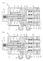
- Figure 8 represents a compressor 114 according to a further embodiment of the invention, wherein the compressor 114 is shown in an intake state.
- the main components or elements of the compressor 114 are similar or equal to that of the compressor 14 described in accordance with the preceding embodiment.
- the compressor 114 comprises a support 132, an elongated plate 134, a body 140, two opposing plates 136, mounting holes 138, damping plates 178, a compression piston 160, a blind hole 146, a fluid passageway 148, an inlet chamber 144, a pipe 152, and an inlet 128.
- the function of these elements is equal to that described above with respect to the embodiment according to Figures 3 to 7 .
- the guiding piston 156 does not comprise any passageway or channel. It may be a solid block having a rod-like shape.
- a hydraulic fluid passage 158 is formed within the body 140.
- the hydraulic fluid passage 158 may be connected to a hose (not shown), which may be further connected to a hydraulic actuator (not shown) for providing hydraulic fluid or hydraulic fluid pressure.
- the fluid passage 158 passes from a sidewall of the blind hole 146 or a bottom of the blind hole 146 through the body 140 to a surface of the body 140. Then, the body 140 and the guiding piston 156 act as a hydraulic ram that can reciprocate the body 140 relative to the support 132.
- Figure 9 represents a compressor 214 according to a third embodiment of the invention, wherein the compressor 214 is represented in an intake state.
- the main components or elements of the compressor 214 are similar or equal to that of the compressors 14, 114 described in accordance with the preceding embodiments.
- the compressor 214 comprises a support 232, an elongated plate 234, a body 240, two opposing plates 236, mounting holes 238, damping plates 278, a compression piston 260, a compression chamber 242, an aperture 250, a blind hole 246, a guiding piston 256, a blind hole 246, a fluid passageway 248, an inlet chamber 244, a pipe 252, and an inlet 228.
- the compression piston 260 forms a solid block or bar similar to the guiding piston 156 according to Figure 8 .
- the compression piston 260 does not allow any through flow and seals the compression chamber 242.
- the body 240 comprises a channel 280 for fluid communication between the compression chamber 242 and the annular tire cavity.
- the channel 280 is formed in the body 240 and forms or is connected to an air outlet 230 of the compressor 214.
- the body 240 and/or the air outlet 230 may comprise a check valve 264 in fluid communication with the channel 280.
- the check valve 264 may be disposed within the body 240, or may be fixed to the body 240. Further, the check valve 264 may be connected to the channel 280.
- the channel 280 may form an aperture 282 in the compression chamber 242, wherein the aperture 282 is disposed closer to the bottom of the compression chamber 242 than the aperture 250 which is in fluid communication with the air inlet 228.
- the embodiment according to Figure 8 and the embodiment according to Figure 9 are combined.
- the body may comprise a hydraulic fluid passage in fluid communication with the blind hole and a duct in fluid communication with the compression chamber.
- At least one of the compression piston and the guiding piston may be a solid rod.
Landscapes
- Engineering & Computer Science (AREA)
- Mechanical Engineering (AREA)
- General Engineering & Computer Science (AREA)
- Compressor (AREA)
- Compressors, Vaccum Pumps And Other Relevant Systems (AREA)
- Tires In General (AREA)
Applications Claiming Priority (1)
| Application Number | Priority Date | Filing Date | Title |
|---|---|---|---|
| US14/100,149 US9193226B2 (en) | 2013-12-09 | 2013-12-09 | Compressor for a self-inflating pneumatic tire |
Publications (2)
| Publication Number | Publication Date |
|---|---|
| EP2889164A2 true EP2889164A2 (fr) | 2015-07-01 |
| EP2889164A3 EP2889164A3 (fr) | 2015-07-22 |
Family
ID=52003624
Family Applications (1)
| Application Number | Title | Priority Date | Filing Date |
|---|---|---|---|
| EP14195995.7A Withdrawn EP2889164A3 (fr) | 2013-12-09 | 2014-12-03 | Compresseur pour un pneumatique autogonflant |
Country Status (2)
| Country | Link |
|---|---|
| US (1) | US9193226B2 (fr) |
| EP (1) | EP2889164A3 (fr) |
Families Citing this family (1)
| Publication number | Priority date | Publication date | Assignee | Title |
|---|---|---|---|---|
| CN110605655B (zh) * | 2019-10-16 | 2024-04-30 | 浙江工业大学 | 一种用于盲孔抛光的抽压气抛光装置及其方法 |
Citations (2)
| Publication number | Priority date | Publication date | Assignee | Title |
|---|---|---|---|---|
| US8156978B1 (en) | 2010-10-18 | 2012-04-17 | The Goodyear Tire & Rubber Company | Tire and self-inflation apparatus assembly |
| US20120160386A1 (en) | 2010-12-22 | 2012-06-28 | Daniel Paul Luc Marie Hinque | Pump and actuator assembly for a self-inflating tire |
Family Cites Families (10)
| Publication number | Priority date | Publication date | Assignee | Title |
|---|---|---|---|---|
| US5355924A (en) * | 1992-10-06 | 1994-10-18 | Hughes Aircraft Company | Vehicle wheel including self-inflating mechanism |
| US5556489A (en) * | 1994-01-14 | 1996-09-17 | Pacific Aeromotive Corporation | Wheel-mounted tire inflator |
| US7051778B2 (en) * | 2000-12-22 | 2006-05-30 | Pirelli Pneumatici S.P.A. | Device and method for generating energy in a rolling wheel |
| US6691754B1 (en) * | 2002-07-24 | 2004-02-17 | Daimlerchrysler Corporation | Electromagnetically activated on-wheel air pump |
| JP4121893B2 (ja) | 2003-05-01 | 2008-07-23 | 横浜ゴム株式会社 | タイヤの自動空気圧調整装置 |
| US6994136B2 (en) * | 2003-05-02 | 2006-02-07 | Arvinmeritor Technology, Llc | Wheel end tire air pump |
| ATE520549T1 (de) * | 2004-11-12 | 2011-09-15 | Richard Loewe | Vorrichtung zur erhaltung des reifendrucks |
| US7322392B2 (en) * | 2005-06-17 | 2008-01-29 | Delphi Technologies, Inc. | Tire pump |
| WO2010141638A1 (fr) | 2009-06-02 | 2010-12-09 | Czero, Inc. | Systèmes et procédés de gonflement de pneu et réglage de la pression |
| US8820376B2 (en) * | 2011-08-05 | 2014-09-02 | The Goodyear Tire & Rubber Company | Diaphragm pump for self-inflating tire |
-
2013
- 2013-12-09 US US14/100,149 patent/US9193226B2/en active Active
-
2014
- 2014-12-03 EP EP14195995.7A patent/EP2889164A3/fr not_active Withdrawn
Patent Citations (2)
| Publication number | Priority date | Publication date | Assignee | Title |
|---|---|---|---|---|
| US8156978B1 (en) | 2010-10-18 | 2012-04-17 | The Goodyear Tire & Rubber Company | Tire and self-inflation apparatus assembly |
| US20120160386A1 (en) | 2010-12-22 | 2012-06-28 | Daniel Paul Luc Marie Hinque | Pump and actuator assembly for a self-inflating tire |
Also Published As
| Publication number | Publication date |
|---|---|
| EP2889164A3 (fr) | 2015-07-22 |
| US20150158349A1 (en) | 2015-06-11 |
| US9193226B2 (en) | 2015-11-24 |
Similar Documents
| Publication | Publication Date | Title |
|---|---|---|
| US9726160B2 (en) | Double acting fluid pump with spring biased piston | |
| EP2889165A2 (fr) | Compresseur d'air pour un pneu et pneu comprenant un compresseur monté dans la cavité du pneumatique | |
| EP2565059B1 (fr) | Pneu | |
| EP2889163A2 (fr) | Compresseur d'air pour un pneu et pneu comprenant un compresseur monté dans la cavité du pneumatique | |
| KR20120071358A (ko) | 자동 팽창식 타이어 시스템 | |
| EP2405137B1 (fr) | Pompe | |
| US20130011283A1 (en) | Air Compressor | |
| WO2016073075A1 (fr) | Pompe à fluide à commande pneumatique à pression de fluide amplifiée et procédés associés | |
| KR20060049931A (ko) | 모터 차량용 스프링 시스템 | |
| CN217539625U (zh) | 用于充气产品的恒压阀和充气产品 | |
| JP6453471B2 (ja) | ピストンポンプ | |
| KR20170020826A (ko) | 압축 다이아프램 펌프에 대한 진동-저감 구조 | |
| EP2871080A1 (fr) | Pneumatique qui comprend un actionneur ou moteur hydraulique | |
| EP3299187A1 (fr) | Ensemble de jante et système de maintenance d'air | |
| CN101815864A (zh) | 用于输送流体的活塞泵和相应的制动系统 | |
| CN110617200B (zh) | 流体泵和相关的系统和方法 | |
| CA2442224C (fr) | Combinaison d'une chambre et d'un piston, pompe, moteur, amortisseur et transducteur integrant ladite combinaison | |
| EP2889164A2 (fr) | Compresseur pour un pneumatique autogonflant | |
| EP3299188A1 (fr) | Ensemble pneumatique à tige de soupape modifiée | |
| US20040009081A1 (en) | Pneumatic pinch mechanism for a deformable tube | |
| CN106103062A (zh) | 用于对可充气物体进行密封和充气的装置 | |
| KR101021532B1 (ko) | 브레이크 시스템의 펌프 | |
| EP3170684B1 (fr) | Maintien de pression d'air dans un pneu à l'aide d'une tige de valve et procédé | |
| US10155422B2 (en) | Temperature compensated self-inflating tire system | |
| US8075286B2 (en) | Compressor for liquid or gaseous fluids |
Legal Events
| Date | Code | Title | Description |
|---|---|---|---|
| PUAL | Search report despatched |
Free format text: ORIGINAL CODE: 0009013 |
|
| PUAI | Public reference made under article 153(3) epc to a published international application that has entered the european phase |
Free format text: ORIGINAL CODE: 0009012 |
|
| 17P | Request for examination filed |
Effective date: 20141203 |
|
| AK | Designated contracting states |
Kind code of ref document: A2 Designated state(s): AL AT BE BG CH CY CZ DE DK EE ES FI FR GB GR HR HU IE IS IT LI LT LU LV MC MK MT NL NO PL PT RO RS SE SI SK SM TR |
|
| AX | Request for extension of the european patent |
Extension state: BA ME |
|
| AK | Designated contracting states |
Kind code of ref document: A3 Designated state(s): AL AT BE BG CH CY CZ DE DK EE ES FI FR GB GR HR HU IE IS IT LI LT LU LV MC MK MT NL NO PL PT RO RS SE SI SK SM TR |
|
| AX | Request for extension of the european patent |
Extension state: BA ME |
|
| RIC1 | Information provided on ipc code assigned before grant |
Ipc: B60C 29/00 20060101AFI20150612BHEP Ipc: B60C 23/12 20060101ALI20150612BHEP |
|
| R17P | Request for examination filed (corrected) |
Effective date: 20160122 |
|
| RBV | Designated contracting states (corrected) |
Designated state(s): AL AT BE BG CH CY CZ DE DK EE ES FI FR GB GR HR HU IE IS IT LI LT LU LV MC MK MT NL NO PL PT RO RS SE SI SK SM TR |
|
| STAA | Information on the status of an ep patent application or granted ep patent |
Free format text: STATUS: THE APPLICATION HAS BEEN WITHDRAWN |
|
| 18W | Application withdrawn |
Effective date: 20160418 |