EP2889179A2 - Verfahren und System für ein Elektrofahrzeug - Google Patents
Verfahren und System für ein Elektrofahrzeug Download PDFInfo
- Publication number
- EP2889179A2 EP2889179A2 EP14191294.9A EP14191294A EP2889179A2 EP 2889179 A2 EP2889179 A2 EP 2889179A2 EP 14191294 A EP14191294 A EP 14191294A EP 2889179 A2 EP2889179 A2 EP 2889179A2
- Authority
- EP
- European Patent Office
- Prior art keywords
- current
- motor
- motor speed
- controller
- operating point
- Prior art date
- Legal status (The legal status is an assumption and is not a legal conclusion. Google has not performed a legal analysis and makes no representation as to the accuracy of the status listed.)
- Granted
Links
Images

Classifications
-
- B—PERFORMING OPERATIONS; TRANSPORTING
- B60—VEHICLES IN GENERAL
- B60L—PROPULSION OF ELECTRICALLY-PROPELLED VEHICLES; SUPPLYING ELECTRIC POWER FOR AUXILIARY EQUIPMENT OF ELECTRICALLY-PROPELLED VEHICLES; ELECTRODYNAMIC BRAKE SYSTEMS FOR VEHICLES IN GENERAL; MAGNETIC SUSPENSION OR LEVITATION FOR VEHICLES; MONITORING OPERATING VARIABLES OF ELECTRICALLY-PROPELLED VEHICLES; ELECTRIC SAFETY DEVICES FOR ELECTRICALLY-PROPELLED VEHICLES
- B60L50/00—Electric propulsion with power supplied within the vehicle
- B60L50/50—Electric propulsion with power supplied within the vehicle using propulsion power supplied by batteries or fuel cells
-
- B—PERFORMING OPERATIONS; TRANSPORTING
- B60—VEHICLES IN GENERAL
- B60L—PROPULSION OF ELECTRICALLY-PROPELLED VEHICLES; SUPPLYING ELECTRIC POWER FOR AUXILIARY EQUIPMENT OF ELECTRICALLY-PROPELLED VEHICLES; ELECTRODYNAMIC BRAKE SYSTEMS FOR VEHICLES IN GENERAL; MAGNETIC SUSPENSION OR LEVITATION FOR VEHICLES; MONITORING OPERATING VARIABLES OF ELECTRICALLY-PROPELLED VEHICLES; ELECTRIC SAFETY DEVICES FOR ELECTRICALLY-PROPELLED VEHICLES
- B60L15/00—Methods, circuits, or devices for controlling the traction-motor speed of electrically-propelled vehicles
- B60L15/20—Methods, circuits, or devices for controlling the traction-motor speed of electrically-propelled vehicles for control of the vehicle or its driving motor to achieve a desired performance, e.g. speed, torque, programmed variation of speed
- B60L15/2045—Methods, circuits, or devices for controlling the traction-motor speed of electrically-propelled vehicles for control of the vehicle or its driving motor to achieve a desired performance, e.g. speed, torque, programmed variation of speed for optimising the use of energy
-
- B—PERFORMING OPERATIONS; TRANSPORTING
- B60—VEHICLES IN GENERAL
- B60K—ARRANGEMENT OR MOUNTING OF PROPULSION UNITS OR OF TRANSMISSIONS IN VEHICLES; ARRANGEMENT OR MOUNTING OF PLURAL DIVERSE PRIME-MOVERS IN VEHICLES; AUXILIARY DRIVES FOR VEHICLES; INSTRUMENTATION OR DASHBOARDS FOR VEHICLES; ARRANGEMENTS IN CONNECTION WITH COOLING, AIR INTAKE, GAS EXHAUST OR FUEL SUPPLY OF PROPULSION UNITS IN VEHICLES
- B60K1/00—Arrangement or mounting of electrical propulsion units
-
- B—PERFORMING OPERATIONS; TRANSPORTING
- B60—VEHICLES IN GENERAL
- B60L—PROPULSION OF ELECTRICALLY-PROPELLED VEHICLES; SUPPLYING ELECTRIC POWER FOR AUXILIARY EQUIPMENT OF ELECTRICALLY-PROPELLED VEHICLES; ELECTRODYNAMIC BRAKE SYSTEMS FOR VEHICLES IN GENERAL; MAGNETIC SUSPENSION OR LEVITATION FOR VEHICLES; MONITORING OPERATING VARIABLES OF ELECTRICALLY-PROPELLED VEHICLES; ELECTRIC SAFETY DEVICES FOR ELECTRICALLY-PROPELLED VEHICLES
- B60L15/00—Methods, circuits, or devices for controlling the traction-motor speed of electrically-propelled vehicles
- B60L15/02—Methods, circuits, or devices for controlling the traction-motor speed of electrically-propelled vehicles characterised by the form of the current used in the control circuit
- B60L15/025—Methods, circuits, or devices for controlling the traction-motor speed of electrically-propelled vehicles characterised by the form of the current used in the control circuit using field orientation; Vector control; Direct Torque Control [DTC]
-
- B—PERFORMING OPERATIONS; TRANSPORTING
- B60—VEHICLES IN GENERAL
- B60L—PROPULSION OF ELECTRICALLY-PROPELLED VEHICLES; SUPPLYING ELECTRIC POWER FOR AUXILIARY EQUIPMENT OF ELECTRICALLY-PROPELLED VEHICLES; ELECTRODYNAMIC BRAKE SYSTEMS FOR VEHICLES IN GENERAL; MAGNETIC SUSPENSION OR LEVITATION FOR VEHICLES; MONITORING OPERATING VARIABLES OF ELECTRICALLY-PROPELLED VEHICLES; ELECTRIC SAFETY DEVICES FOR ELECTRICALLY-PROPELLED VEHICLES
- B60L3/00—Electric devices on electrically-propelled vehicles for safety purposes; Monitoring operating variables, e.g. speed, deceleration or energy consumption
- B60L3/12—Recording operating variables ; Monitoring of operating variables
-
- B—PERFORMING OPERATIONS; TRANSPORTING
- B60—VEHICLES IN GENERAL
- B60L—PROPULSION OF ELECTRICALLY-PROPELLED VEHICLES; SUPPLYING ELECTRIC POWER FOR AUXILIARY EQUIPMENT OF ELECTRICALLY-PROPELLED VEHICLES; ELECTRODYNAMIC BRAKE SYSTEMS FOR VEHICLES IN GENERAL; MAGNETIC SUSPENSION OR LEVITATION FOR VEHICLES; MONITORING OPERATING VARIABLES OF ELECTRICALLY-PROPELLED VEHICLES; ELECTRIC SAFETY DEVICES FOR ELECTRICALLY-PROPELLED VEHICLES
- B60L50/00—Electric propulsion with power supplied within the vehicle
- B60L50/50—Electric propulsion with power supplied within the vehicle using propulsion power supplied by batteries or fuel cells
- B60L50/51—Electric propulsion with power supplied within the vehicle using propulsion power supplied by batteries or fuel cells characterised by AC-motors
-
- B—PERFORMING OPERATIONS; TRANSPORTING
- B60—VEHICLES IN GENERAL
- B60W—CONJOINT CONTROL OF VEHICLE SUB-UNITS OF DIFFERENT TYPE OR DIFFERENT FUNCTION; CONTROL SYSTEMS SPECIALLY ADAPTED FOR HYBRID VEHICLES; ROAD VEHICLE DRIVE CONTROL SYSTEMS FOR PURPOSES NOT RELATED TO THE CONTROL OF A PARTICULAR SUB-UNIT
- B60W10/00—Conjoint control of vehicle sub-units of different type or different function
-
- B—PERFORMING OPERATIONS; TRANSPORTING
- B60—VEHICLES IN GENERAL
- B60W—CONJOINT CONTROL OF VEHICLE SUB-UNITS OF DIFFERENT TYPE OR DIFFERENT FUNCTION; CONTROL SYSTEMS SPECIALLY ADAPTED FOR HYBRID VEHICLES; ROAD VEHICLE DRIVE CONTROL SYSTEMS FOR PURPOSES NOT RELATED TO THE CONTROL OF A PARTICULAR SUB-UNIT
- B60W20/00—Control systems specially adapted for hybrid vehicles
-
- B—PERFORMING OPERATIONS; TRANSPORTING
- B60—VEHICLES IN GENERAL
- B60L—PROPULSION OF ELECTRICALLY-PROPELLED VEHICLES; SUPPLYING ELECTRIC POWER FOR AUXILIARY EQUIPMENT OF ELECTRICALLY-PROPELLED VEHICLES; ELECTRODYNAMIC BRAKE SYSTEMS FOR VEHICLES IN GENERAL; MAGNETIC SUSPENSION OR LEVITATION FOR VEHICLES; MONITORING OPERATING VARIABLES OF ELECTRICALLY-PROPELLED VEHICLES; ELECTRIC SAFETY DEVICES FOR ELECTRICALLY-PROPELLED VEHICLES
- B60L2240/00—Control parameters of input or output; Target parameters
- B60L2240/40—Drive Train control parameters
- B60L2240/42—Drive Train control parameters related to electric machines
- B60L2240/421—Speed
-
- B—PERFORMING OPERATIONS; TRANSPORTING
- B60—VEHICLES IN GENERAL
- B60L—PROPULSION OF ELECTRICALLY-PROPELLED VEHICLES; SUPPLYING ELECTRIC POWER FOR AUXILIARY EQUIPMENT OF ELECTRICALLY-PROPELLED VEHICLES; ELECTRODYNAMIC BRAKE SYSTEMS FOR VEHICLES IN GENERAL; MAGNETIC SUSPENSION OR LEVITATION FOR VEHICLES; MONITORING OPERATING VARIABLES OF ELECTRICALLY-PROPELLED VEHICLES; ELECTRIC SAFETY DEVICES FOR ELECTRICALLY-PROPELLED VEHICLES
- B60L2240/00—Control parameters of input or output; Target parameters
- B60L2240/40—Drive Train control parameters
- B60L2240/42—Drive Train control parameters related to electric machines
- B60L2240/423—Torque
-
- B—PERFORMING OPERATIONS; TRANSPORTING
- B60—VEHICLES IN GENERAL
- B60L—PROPULSION OF ELECTRICALLY-PROPELLED VEHICLES; SUPPLYING ELECTRIC POWER FOR AUXILIARY EQUIPMENT OF ELECTRICALLY-PROPELLED VEHICLES; ELECTRODYNAMIC BRAKE SYSTEMS FOR VEHICLES IN GENERAL; MAGNETIC SUSPENSION OR LEVITATION FOR VEHICLES; MONITORING OPERATING VARIABLES OF ELECTRICALLY-PROPELLED VEHICLES; ELECTRIC SAFETY DEVICES FOR ELECTRICALLY-PROPELLED VEHICLES
- B60L2240/00—Control parameters of input or output; Target parameters
- B60L2240/40—Drive Train control parameters
- B60L2240/42—Drive Train control parameters related to electric machines
- B60L2240/427—Voltage
-
- B—PERFORMING OPERATIONS; TRANSPORTING
- B60—VEHICLES IN GENERAL
- B60L—PROPULSION OF ELECTRICALLY-PROPELLED VEHICLES; SUPPLYING ELECTRIC POWER FOR AUXILIARY EQUIPMENT OF ELECTRICALLY-PROPELLED VEHICLES; ELECTRODYNAMIC BRAKE SYSTEMS FOR VEHICLES IN GENERAL; MAGNETIC SUSPENSION OR LEVITATION FOR VEHICLES; MONITORING OPERATING VARIABLES OF ELECTRICALLY-PROPELLED VEHICLES; ELECTRIC SAFETY DEVICES FOR ELECTRICALLY-PROPELLED VEHICLES
- B60L2240/00—Control parameters of input or output; Target parameters
- B60L2240/40—Drive Train control parameters
- B60L2240/42—Drive Train control parameters related to electric machines
- B60L2240/429—Current
-
- B—PERFORMING OPERATIONS; TRANSPORTING
- B60—VEHICLES IN GENERAL
- B60L—PROPULSION OF ELECTRICALLY-PROPELLED VEHICLES; SUPPLYING ELECTRIC POWER FOR AUXILIARY EQUIPMENT OF ELECTRICALLY-PROPELLED VEHICLES; ELECTRODYNAMIC BRAKE SYSTEMS FOR VEHICLES IN GENERAL; MAGNETIC SUSPENSION OR LEVITATION FOR VEHICLES; MONITORING OPERATING VARIABLES OF ELECTRICALLY-PROPELLED VEHICLES; ELECTRIC SAFETY DEVICES FOR ELECTRICALLY-PROPELLED VEHICLES
- B60L2240/00—Control parameters of input or output; Target parameters
- B60L2240/40—Drive Train control parameters
- B60L2240/54—Drive Train control parameters related to batteries
- B60L2240/547—Voltage
-
- B—PERFORMING OPERATIONS; TRANSPORTING
- B60—VEHICLES IN GENERAL
- B60L—PROPULSION OF ELECTRICALLY-PROPELLED VEHICLES; SUPPLYING ELECTRIC POWER FOR AUXILIARY EQUIPMENT OF ELECTRICALLY-PROPELLED VEHICLES; ELECTRODYNAMIC BRAKE SYSTEMS FOR VEHICLES IN GENERAL; MAGNETIC SUSPENSION OR LEVITATION FOR VEHICLES; MONITORING OPERATING VARIABLES OF ELECTRICALLY-PROPELLED VEHICLES; ELECTRIC SAFETY DEVICES FOR ELECTRICALLY-PROPELLED VEHICLES
- B60L2240/00—Control parameters of input or output; Target parameters
- B60L2240/40—Drive Train control parameters
- B60L2240/54—Drive Train control parameters related to batteries
- B60L2240/549—Current
-
- B—PERFORMING OPERATIONS; TRANSPORTING
- B60—VEHICLES IN GENERAL
- B60L—PROPULSION OF ELECTRICALLY-PROPELLED VEHICLES; SUPPLYING ELECTRIC POWER FOR AUXILIARY EQUIPMENT OF ELECTRICALLY-PROPELLED VEHICLES; ELECTRODYNAMIC BRAKE SYSTEMS FOR VEHICLES IN GENERAL; MAGNETIC SUSPENSION OR LEVITATION FOR VEHICLES; MONITORING OPERATING VARIABLES OF ELECTRICALLY-PROPELLED VEHICLES; ELECTRIC SAFETY DEVICES FOR ELECTRICALLY-PROPELLED VEHICLES
- B60L2260/00—Operating Modes
- B60L2260/40—Control modes
- B60L2260/44—Control modes by parameter estimation
-
- H—ELECTRICITY
- H02—GENERATION; CONVERSION OR DISTRIBUTION OF ELECTRIC POWER
- H02P—CONTROL OR REGULATION OF ELECTRIC MOTORS, ELECTRIC GENERATORS OR DYNAMO-ELECTRIC CONVERTERS; CONTROLLING TRANSFORMERS, REACTORS OR CHOKE COILS
- H02P21/00—Arrangements or methods for the control of electric machines by vector control, e.g. by control of field orientation
- H02P21/22—Current control, e.g. using a current control loop
-
- Y—GENERAL TAGGING OF NEW TECHNOLOGICAL DEVELOPMENTS; GENERAL TAGGING OF CROSS-SECTIONAL TECHNOLOGIES SPANNING OVER SEVERAL SECTIONS OF THE IPC; TECHNICAL SUBJECTS COVERED BY FORMER USPC CROSS-REFERENCE ART COLLECTIONS [XRACs] AND DIGESTS
- Y02—TECHNOLOGIES OR APPLICATIONS FOR MITIGATION OR ADAPTATION AGAINST CLIMATE CHANGE
- Y02T—CLIMATE CHANGE MITIGATION TECHNOLOGIES RELATED TO TRANSPORTATION
- Y02T10/00—Road transport of goods or passengers
- Y02T10/10—Internal combustion engine [ICE] based vehicles
- Y02T10/40—Engine management systems
-
- Y—GENERAL TAGGING OF NEW TECHNOLOGICAL DEVELOPMENTS; GENERAL TAGGING OF CROSS-SECTIONAL TECHNOLOGIES SPANNING OVER SEVERAL SECTIONS OF THE IPC; TECHNICAL SUBJECTS COVERED BY FORMER USPC CROSS-REFERENCE ART COLLECTIONS [XRACs] AND DIGESTS
- Y02—TECHNOLOGIES OR APPLICATIONS FOR MITIGATION OR ADAPTATION AGAINST CLIMATE CHANGE
- Y02T—CLIMATE CHANGE MITIGATION TECHNOLOGIES RELATED TO TRANSPORTATION
- Y02T10/00—Road transport of goods or passengers
- Y02T10/60—Other road transportation technologies with climate change mitigation effect
- Y02T10/64—Electric machine technologies in electromobility
-
- Y—GENERAL TAGGING OF NEW TECHNOLOGICAL DEVELOPMENTS; GENERAL TAGGING OF CROSS-SECTIONAL TECHNOLOGIES SPANNING OVER SEVERAL SECTIONS OF THE IPC; TECHNICAL SUBJECTS COVERED BY FORMER USPC CROSS-REFERENCE ART COLLECTIONS [XRACs] AND DIGESTS
- Y02—TECHNOLOGIES OR APPLICATIONS FOR MITIGATION OR ADAPTATION AGAINST CLIMATE CHANGE
- Y02T—CLIMATE CHANGE MITIGATION TECHNOLOGIES RELATED TO TRANSPORTATION
- Y02T10/00—Road transport of goods or passengers
- Y02T10/60—Other road transportation technologies with climate change mitigation effect
- Y02T10/70—Energy storage systems for electromobility, e.g. batteries
-
- Y—GENERAL TAGGING OF NEW TECHNOLOGICAL DEVELOPMENTS; GENERAL TAGGING OF CROSS-SECTIONAL TECHNOLOGIES SPANNING OVER SEVERAL SECTIONS OF THE IPC; TECHNICAL SUBJECTS COVERED BY FORMER USPC CROSS-REFERENCE ART COLLECTIONS [XRACs] AND DIGESTS
- Y02—TECHNOLOGIES OR APPLICATIONS FOR MITIGATION OR ADAPTATION AGAINST CLIMATE CHANGE
- Y02T—CLIMATE CHANGE MITIGATION TECHNOLOGIES RELATED TO TRANSPORTATION
- Y02T10/00—Road transport of goods or passengers
- Y02T10/60—Other road transportation technologies with climate change mitigation effect
- Y02T10/72—Electric energy management in electromobility
Definitions
- the present invention relates to a control method and system of an electric vehicle. More particularly, the present invention relates to a control method and system of an electric vehicle that reduces fuel consumption and cost by more efficiently controlling a motor disposed within the electric vehicle.
- An electric vehicle has been developed to help with environmental pollution by developing alternative energy sources.
- An electric vehicle includes a motor that is configured to propel the vehicle and a high voltage battery that is configured to supply power to the motor.
- a battery is an energy source used to drive the motor, and is configured to supply power to the motor using an inverter.
- a maximum torque per ampere (MTPA) control method is one existing motor control method.
- the MTPA control method sets a current map by sweeping current supplied to the motor.
- the MTPA control method controls the motor using mathematical modeling, but the nonlinearity of the motor cannot be represented by a mathematical equation causing the mathematical modeling to usually be ineffective.
- a motor control method that sets a current map from an operating point that minimizes output current of the motor is used.
- an operating point can be calculated from an equal torque region obtained by current sweep.
- the measuring factors e.g., motor torque, motor current, motor voltage, power factor of the motor, direct current (DC) voltage, and DC current
- DC direct current
- the present invention provides a control method of an electric vehicle that may reduce fuel consumption and cost by more efficiently controlling a motor disposed within an electric vehicle. Further, the present invention provides a control method of an electric vehicle that may reduce cost of a motor control system and may also simplify the motor control system.
- a control method of an electric vehicle may include: supplying electricity using a battery operated by a controller, receiving electricity from the battery and generating power using a motor operated by a controller, detecting, by the controller, a torque command, a motor speed, and a motor current; calculating, by the controller, a motor voltage using the motor current; determining, by the controller, when voltage utilization ,based on a speed range of the motor, is greater than a predetermined value; generating, by the controller, an operating point correcting function, based on the motor speed, in response to the voltage utilization being less than the predetermined value; calculating, by the controller, a current command ,based on the motor speed, from the operating point correcting function; and outputting, by the controller, the calculated current command.
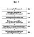
- the generation of an operating point correcting function may include: determining a maximum efficiency driving current map from a first motor speed; calculating a first current magnitude and a first current angle using the first motor speed; determining a maximum efficiency operating point from a second motor speed; calculating a second current magnitude and a second current angle from the second motor speed; and generating the operating point correcting function from the first and second current magnitude and the first and second current angle.
- the current map may be set using the first motor speed by sweeping a first direct current (DC) supplied from the battery.
- the operating point may be set using the second motor speed by sweeping a second DC supplied from the battery.
- the generation of the operating point correcting function may further include calculating a difference of the first and second current magnitude and a difference of the first and second current angle; and generating the operating point correcting function by approximating the difference of the current magnitude and the current angle.
- the difference of the current magnitude and the current angle may be approximated using a predetermined quadratic function.
- the control method of an electric vehicle may further include operating the motor using overmodulation in response to the voltage utilization being greater than a predetermined value.
- an optimal operating point may be set based on a motor speed through an operating point correcting function, fuel consumption of a vehicle may be reduced. Further, since measuring factors necessary for controlling a motor may be minimized, system configuration may be simplified.
- vehicle or “vehicular” or other similar term as used herein is inclusive of motor vehicles in general such as passenger automobiles including sports utility vehicles (SUV), buses, trucks, various commercial vehicles, watercraft including a variety of boats and ships, aircraft, and the like, and includes hybrid vehicles, electric vehicles, plug-in hybrid electric vehicles, hydrogen-powered vehicles and other alternative fuel vehicles (e.g. fuels derived from resources other than petroleum).
- a hybrid vehicle is a vehicle that has two or more sources of power, for example both gasoline-powered and electric-powered vehicles.
- controller/control unit refers to a hardware device that includes a memory and a processor.
- the memory is configured to store the modules and the processor is specifically configured to execute said modules to perform one or more processes which are described further below.
- control logic of the present invention may be embodied as non-transitory computer readable media on a computer readable medium containing executable program instructions executed by a processor, controller/control unit or the like.
- the computer readable mediums include, but are not limited to, ROM, RAM, compact disc (CD)-ROMs, magnetic tapes, floppy disks, flash drives, smart cards and optical data storage devices.
- the computer readable recording medium can also be distributed in network coupled computer systems so that the computer readable media is stored and executed in a distributed fashion, e.g., by a telematics server or a Controller Area Network (CAN).
- a telematics server or a Controller Area Network (CAN).
- CAN Controller Area Network
- FIG. 1 is an exemplary block diagram illustrating an electric vehicle according to an exemplary embodiment of the present invention.
- an electric vehicle may include a battery 10 configured to supply electricity, a motor 30 configured to receive electricity from the battery 10 and generate power, and a controller 20 configured to operate the battery 10 and the motor 30.
- the battery 10 may be operated by the controller to supply direct current power (DC power), and particularly supply substantially constant voltage power.
- DC power direct current power
- the controller 20 may include one or more microprocessors operated by a predetermined program or hardware that includes the microprocessor.
- the predetermined program may include a series of commands configured to perform a control method of an electric vehicle according to an exemplary embodiment of the present invention to be described below.
- the controller 20 may be an inverter configured to receive electricity from the battery 10 and operate the motor 30.
- FIG. 2 is an exemplary flowchart illustrating a control method of an electric vehicle according to an exemplary embodiment of the present invention.
- the controller 20 may be configured to detect a motor speed and current (S120), and the controller 20 may be configured to calculate a motor voltage from the motor current (S130).
- the controller 20 may also be configured to determine whether voltage utilization of the motor 30 is greater than about 1 (S140).
- the controller may be configured to deteremine a substantial amount of voltage is used in a relatively high speed range (e.g., predetermined speed range) and may further be configured to operate the motor 30 by overmodulation (S150).
- An overmodulation control method is generally known to those skilled in the art, and detailed description thereof will be omitted.
- the controller 20 may be configured to calculate an operating point correcting function based on the motor speed (S200).
- the controller 20 may be configured to set a current map with respect to a first motor speed by sweeping a first direct current supplied from the battery 10 (S210).
- the first motor speed may be about 1500 revolutions per minute (RPM).
- the controller 20 may be configured to calculate a first magnitude (Is1) of a first d-axis current (Id1) and a first q-axis current (Iq1), and a first angle (Beta1) of the first d-axis current (Id1) and the first q-axis current (Iq1) within a synchronous reference frame with respect to a torque command at the first motor speed (S220).
- the controller 20 may be configured to set an operating point with respect to a second motor speed by sweeping a second direct current supplied from the battery 10 (S230).
- controller 20 may be configured to calculate a second magnitude (Is2) of a second d-axis current (Id2) and a second q-axis current (Iq2), and a second angle (Beta2) of the second d-axis current (Id2) and the second q-axis current (Iq2) with respect to the second motor speed (S240).
- the controller 20 may be configured to calculate a difference between the first and second current magnitude and a difference between the first and second current angle (S250).
- the difference (Delta_Is) of the current magnitude may be a difference between Is1 and Is2.
- the difference (Delta_Beta) of the current angle may be a difference between Beta1 and Beta2.
- the controller 20 may further be configured to approximate the difference of the current magnitude (Delta_Is) and the difference of the current angle (Delta_Beta), and calculate an operating point correcting function (Func_Delta_Is, Func_Delta_Beta) (S260).
- the controller 20 may be configured to obtain a maximum efficiency operating point within overall speed range by interpolating the first d-axis current (Id1) c and the second d-axis current (Id2) and by interpolating the first q-axis current (Iq1) and the first q-axis current (Iq2).
- the controller 20 may be configured to calculate the operating point correcting function by a linear function or a quadratic function, when the controller 20 interpolates the d-axis current (Id1) calculated from the first motor speed and the d-axis current (Id2) calculated from the second motor speed, or when the q-axis current (Iq1) calculated from the first motor speed and the q-axis current (Iq2) calculated from the second motor speed.
- the controller 20 may be configured to calculate a current command with respect to the motor speed using the operating point correcting function (S300).
- the controller 20 may be configured to calculate a new current magnitude (Is_new) and a new current angle (Beta_new) using the operating point correcting function (S310).
- the Func_Delta_Is() is the operating point correcting function of a current magnitude
- the Func_Delta_Beta() is the operating point correcting function of a current angle
- the controller 20 may be configured to calculate a new d-axis current command (Id_new) and a new q-axis current command (Iq_new) within a synchronous reference frame from the new current magnitude (Is_new) and the new current angle (Beta_new) at step S320.
- the controller 20 may be configured to then output the new d-axis current command (Id_new) and the new q-axis current command (Iq_new) to the motor 30.
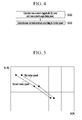
- FIG. 5 is an exemplary graph illustrating an operating point according to a motor speed according to an exemplary embodiment of the present invention.
- FIG. 5 illustrates an operating point obtained from the first motor speed (e.g., about 1500 RPM) and an operating point obtained from the second motor speed (e.g., about 2000 RPM).
- the motor 30 may be operated while also taking the variation of core loss based on motor speed into account, which allows for a maximized efficiency while driving based on motor speed.
- a current map may be set for one motor speed.
- the maximum efficient operating point may be the minimum point of DC current. Therefore, a current map determined by direct current of the battery and required torque may become a maximum efficiency current map. By using this method, a measuring error may be reduced and a measuring system may be simplified.
- the motor since the motor may be operated by measuring direct current of the battery, it may be possible to operate the motor based on the efficiency of the inverter. Furthermore, a voltage output from the battery may be maintained substantially constant. Therefore, when minimum input power (i.e., direct voltage * direct current) is determined by verifying direct current of the battery, an operating point of maximum efficiency (minimum loss) may be obtained. By using this method, fuel consumption may be reduced.
- minimum input power i.e., direct voltage * direct current
- minimum loss minimum loss
Landscapes
- Engineering & Computer Science (AREA)
- Transportation (AREA)
- Mechanical Engineering (AREA)
- Power Engineering (AREA)
- Life Sciences & Earth Sciences (AREA)
- Sustainable Development (AREA)
- Sustainable Energy (AREA)
- Chemical & Material Sciences (AREA)
- Combustion & Propulsion (AREA)
- Automation & Control Theory (AREA)
- Electric Propulsion And Braking For Vehicles (AREA)
- Control Of Ac Motors In General (AREA)
Applications Claiming Priority (1)
| Application Number | Priority Date | Filing Date | Title |
|---|---|---|---|
| KR20130162932A KR101500397B1 (ko) | 2013-12-24 | 2013-12-24 | 전기 차량의 제어 방법 |
Publications (3)
| Publication Number | Publication Date |
|---|---|
| EP2889179A2 true EP2889179A2 (de) | 2015-07-01 |
| EP2889179A3 EP2889179A3 (de) | 2015-09-23 |
| EP2889179B1 EP2889179B1 (de) | 2019-01-09 |
Family
ID=51947116
Family Applications (1)
| Application Number | Title | Priority Date | Filing Date |
|---|---|---|---|
| EP14191294.9A Active EP2889179B1 (de) | 2013-12-24 | 2014-10-31 | Verfahren und System für ein Elektrofahrzeug |
Country Status (4)
| Country | Link |
|---|---|
| US (1) | US9409486B2 (de) |
| EP (1) | EP2889179B1 (de) |
| KR (1) | KR101500397B1 (de) |
| CN (1) | CN104723900B (de) |
Cited By (1)
| Publication number | Priority date | Publication date | Assignee | Title |
|---|---|---|---|---|
| CN111446897A (zh) * | 2020-04-30 | 2020-07-24 | 上海中科深江电动车辆有限公司 | 用于校准自动标定电机电压利用率的方法 |
Families Citing this family (11)
| Publication number | Priority date | Publication date | Assignee | Title |
|---|---|---|---|---|
| KR101856317B1 (ko) * | 2016-04-18 | 2018-05-10 | 현대자동차주식회사 | 차량의 컨버터 제어방법 및 시스템 |
| KR101875642B1 (ko) * | 2016-04-18 | 2018-07-06 | 현대자동차 주식회사 | 차량용 모터 제어 장치 및 방법 |
| CN106100484B (zh) * | 2016-08-08 | 2018-12-07 | 凯晟动力技术(嘉兴)有限公司 | 一种混合动力汽车电机控制方法 |
| CN106329856A (zh) * | 2016-08-24 | 2017-01-11 | 廖建航 | 基于立式绕线机的电压获取方法及系统 |
| WO2018035777A1 (zh) * | 2016-08-24 | 2018-03-01 | 廖建航 | 电压在卧式绕线机中的确定方法及系统 |
| CN106301135A (zh) * | 2016-08-24 | 2017-01-04 | 廖建航 | 电压在卧式绕线机中的确定方法及系统 |
| WO2018035776A1 (zh) * | 2016-08-24 | 2018-03-01 | 廖建航 | 基于立式绕线机的电压获取方法及系统 |
| CN106094911A (zh) * | 2016-08-24 | 2016-11-09 | 廖建航 | 闭环控制在立式绕线机中的应用方法及系统 |
| CN106253604A (zh) * | 2016-08-24 | 2016-12-21 | 廖建航 | 立式绕线机的电流控制方法及系统 |
| KR20230011009A (ko) * | 2021-07-13 | 2023-01-20 | 현대자동차주식회사 | 차량용 모터 제어 시스템 |
| DE102022131650A1 (de) * | 2022-11-30 | 2024-06-06 | Audi Aktiengesellschaft | Verfahren zur Bestimmung einer prädiktiven Egogeschwindigkeit eines entlang einer vorgegebenen Strecke fahrenden Fahrzeugs, Steuerungseinrichtung für ein Fahrzeug oder für eine Navigationseinrichtung oder für ein mobiles Nutzerendgerät, Navigationsgerät und Fahrzeug |
Family Cites Families (13)
| Publication number | Priority date | Publication date | Assignee | Title |
|---|---|---|---|---|
| JP3903625B2 (ja) * | 1998-12-21 | 2007-04-11 | トヨタ自動車株式会社 | 動力出力装置 |
| JP4718041B2 (ja) * | 2000-11-22 | 2011-07-06 | ダイキン工業株式会社 | インバータ制御方法およびその装置 |
| US7586286B2 (en) * | 2006-11-17 | 2009-09-08 | Continental Automotive Systems Us, Inc. | Method and apparatus for motor control |
| KR100992755B1 (ko) | 2007-12-13 | 2010-11-05 | 기아자동차주식회사 | 하이브리드 차량의 soc별 최적 운전점 결정 방법 |
| JP4957574B2 (ja) * | 2008-02-07 | 2012-06-20 | 株式会社デンソー | 回転機の制御装置及び回転機の制御システム |
| EP2093098B1 (de) | 2008-02-21 | 2010-05-12 | Yamaha Hatsudoki Kabushiki Kaisha | Radantreibende Vorrichtung und elektrisches Fahrzeug damit |
| CN101252336B (zh) * | 2008-03-07 | 2011-12-28 | 清华大学 | 永磁同步电机-压缩机系统高速运行控制方法 |
| JP4582168B2 (ja) | 2008-03-21 | 2010-11-17 | 株式会社デンソー | 回転機の制御装置、及び回転機の制御システム |
| KR101469993B1 (ko) | 2008-06-16 | 2014-12-05 | 현대자동차주식회사 | 전기자동차의 구동모터 제어방법 |
| WO2012104960A1 (ja) * | 2011-01-31 | 2012-08-09 | スズキ株式会社 | ハイブリッド車両の駆動制御装置 |
| JP2013060175A (ja) | 2011-09-15 | 2013-04-04 | Nissan Motor Co Ltd | ハイブリッド車両の制御装置 |
| KR101272955B1 (ko) | 2011-12-07 | 2013-06-12 | 기아자동차주식회사 | 환경자동차용 모터 제어 방법 |
| CN102684576A (zh) * | 2012-05-23 | 2012-09-19 | 东方电气集团东风电机有限公司 | 应用于纯电动轿车的永磁电机控制器及控制方法 |
-
2013
- 2013-12-24 KR KR20130162932A patent/KR101500397B1/ko active Active
-
2014
- 2014-10-31 EP EP14191294.9A patent/EP2889179B1/de active Active
- 2014-10-31 US US14/530,300 patent/US9409486B2/en active Active
- 2014-11-11 CN CN201410643840.XA patent/CN104723900B/zh active Active
Non-Patent Citations (1)
| Title |
|---|
| None |
Cited By (2)
| Publication number | Priority date | Publication date | Assignee | Title |
|---|---|---|---|---|
| CN111446897A (zh) * | 2020-04-30 | 2020-07-24 | 上海中科深江电动车辆有限公司 | 用于校准自动标定电机电压利用率的方法 |
| CN111446897B (zh) * | 2020-04-30 | 2023-05-26 | 上海中科深江电动车辆有限公司 | 用于校准自动标定电机电压利用率的方法 |
Also Published As
| Publication number | Publication date |
|---|---|
| US9409486B2 (en) | 2016-08-09 |
| US20150175015A1 (en) | 2015-06-25 |
| EP2889179A3 (de) | 2015-09-23 |
| EP2889179B1 (de) | 2019-01-09 |
| CN104723900A (zh) | 2015-06-24 |
| KR101500397B1 (ko) | 2015-03-19 |
| CN104723900B (zh) | 2018-06-01 |
Similar Documents
| Publication | Publication Date | Title |
|---|---|---|
| EP2889179B1 (de) | Verfahren und System für ein Elektrofahrzeug | |
| US9083271B2 (en) | Motor control system and method for environmentally-friendly vehicle | |
| US7586286B2 (en) | Method and apparatus for motor control | |
| US9007013B2 (en) | Inverter control method and system for eco-friendly vehicle | |
| US9114724B2 (en) | Control method of hybrid vehicle | |
| US8907613B2 (en) | System and method for controlling motor of electric vehicle | |
| US9484851B2 (en) | Technique for correcting resolver offset | |
| US11563225B2 (en) | System and method of controlling air compressor motor for fuel cell vehicle and system and method of controlling operation of fuel cell vehicle using same | |
| US20150180255A1 (en) | Method and system of calculating battery charge time | |
| CN106274894B (zh) | 控制混合动力车辆的运行模式的装置和方法 | |
| US8664900B2 (en) | System for controlling motor of hybrid vehicle | |
| EP2963806B1 (de) | Vorrichtung und Verfahren zur Steuerung eines 6-Schritt-Wechselrichters für ein Motorantriebssystem | |
| US9789866B2 (en) | Apparatus and method for controlling mode change of hybrid electric vehicle | |
| US8896247B2 (en) | Current sensor reconfiguration method of a vehicle having a motor | |
| US11285836B2 (en) | Method and apparatus for controlling scheduled charging | |
| US10576960B2 (en) | Apparatus and method for calculating maximum output torque of engine of hybrid electric vehicle | |
| US10293701B2 (en) | Control method and system of low-voltage DC-DC converter for hybrid vehicle | |
| US9172316B2 (en) | Inverter control method and system for eco-friendly vehicle | |
| US8884556B2 (en) | System for controlling a motor of vehicle | |
| CN105281593B (zh) | 改善新能源汽车的逆变器的电压利用率的控制装置和方法 | |
| US9614469B2 (en) | Apparatus and method for controlling electric vehicle | |
| CN111775926B (zh) | 增程式电动汽车的驱动模式控制方法及其控制系统 | |
| CN103144551B (zh) | 用于控制电动车的电动机的系统和方法 | |
| CN105098208A (zh) | 用于控制燃料电池车的进气的方法和系统 | |
| US20240190264A1 (en) | Control device for vehicle |
Legal Events
| Date | Code | Title | Description |
|---|---|---|---|
| PUAI | Public reference made under article 153(3) epc to a published international application that has entered the european phase |
Free format text: ORIGINAL CODE: 0009012 |
|
| 17P | Request for examination filed |
Effective date: 20141031 |
|
| AK | Designated contracting states |
Kind code of ref document: A2 Designated state(s): AL AT BE BG CH CY CZ DE DK EE ES FI FR GB GR HR HU IE IS IT LI LT LU LV MC MK MT NL NO PL PT RO RS SE SI SK SM TR |
|
| AX | Request for extension of the european patent |
Extension state: BA ME |
|
| PUAL | Search report despatched |
Free format text: ORIGINAL CODE: 0009013 |
|
| AK | Designated contracting states |
Kind code of ref document: A3 Designated state(s): AL AT BE BG CH CY CZ DE DK EE ES FI FR GB GR HR HU IE IS IT LI LT LU LV MC MK MT NL NO PL PT RO RS SE SI SK SM TR |
|
| AX | Request for extension of the european patent |
Extension state: BA ME |
|
| RIC1 | Information provided on ipc code assigned before grant |
Ipc: B60W 10/00 20060101ALI20150818BHEP Ipc: B60L 15/02 20060101ALI20150818BHEP Ipc: B60K 1/00 20060101ALI20150818BHEP Ipc: B60L 11/18 20060101ALI20150818BHEP Ipc: H02P 21/14 20060101ALI20150818BHEP Ipc: B60W 20/00 20060101ALI20150818BHEP Ipc: H02P 21/00 20060101ALI20150818BHEP Ipc: B60L 3/12 20060101ALI20150818BHEP Ipc: B60L 15/20 20060101AFI20150818BHEP |
|
| R17P | Request for examination filed (corrected) |
Effective date: 20160318 |
|
| RBV | Designated contracting states (corrected) |
Designated state(s): AL AT BE BG CH CY CZ DE DK EE ES FI FR GB GR HR HU IE IS IT LI LT LU LV MC MK MT NL NO PL PT RO RS SE SI SK SM TR |
|
| STAA | Information on the status of an ep patent application or granted ep patent |
Free format text: STATUS: EXAMINATION IS IN PROGRESS |
|
| 17Q | First examination report despatched |
Effective date: 20161109 |
|
| GRAP | Despatch of communication of intention to grant a patent |
Free format text: ORIGINAL CODE: EPIDOSNIGR1 |
|
| STAA | Information on the status of an ep patent application or granted ep patent |
Free format text: STATUS: GRANT OF PATENT IS INTENDED |
|
| INTG | Intention to grant announced |
Effective date: 20180823 |
|
| GRAS | Grant fee paid |
Free format text: ORIGINAL CODE: EPIDOSNIGR3 |
|
| GRAA | (expected) grant |
Free format text: ORIGINAL CODE: 0009210 |
|
| STAA | Information on the status of an ep patent application or granted ep patent |
Free format text: STATUS: THE PATENT HAS BEEN GRANTED |
|
| AK | Designated contracting states |
Kind code of ref document: B1 Designated state(s): AL AT BE BG CH CY CZ DE DK EE ES FI FR GB GR HR HU IE IS IT LI LT LU LV MC MK MT NL NO PL PT RO RS SE SI SK SM TR |
|
| REG | Reference to a national code |
Ref country code: GB Ref legal event code: FG4D |
|
| REG | Reference to a national code |
Ref country code: CH Ref legal event code: EP Ref country code: AT Ref legal event code: REF Ref document number: 1086860 Country of ref document: AT Kind code of ref document: T Effective date: 20190115 |
|
| REG | Reference to a national code |
Ref country code: IE Ref legal event code: FG4D |
|
| REG | Reference to a national code |
Ref country code: DE Ref legal event code: R096 Ref document number: 602014039451 Country of ref document: DE |
|
| REG | Reference to a national code |
Ref country code: NL Ref legal event code: MP Effective date: 20190109 |
|
| REG | Reference to a national code |
Ref country code: LT Ref legal event code: MG4D |
|
| PG25 | Lapsed in a contracting state [announced via postgrant information from national office to epo] |
Ref country code: NL Free format text: LAPSE BECAUSE OF FAILURE TO SUBMIT A TRANSLATION OF THE DESCRIPTION OR TO PAY THE FEE WITHIN THE PRESCRIBED TIME-LIMIT Effective date: 20190109 |
|
| REG | Reference to a national code |
Ref country code: AT Ref legal event code: MK05 Ref document number: 1086860 Country of ref document: AT Kind code of ref document: T Effective date: 20190109 |
|
| PG25 | Lapsed in a contracting state [announced via postgrant information from national office to epo] |
Ref country code: SE Free format text: LAPSE BECAUSE OF FAILURE TO SUBMIT A TRANSLATION OF THE DESCRIPTION OR TO PAY THE FEE WITHIN THE PRESCRIBED TIME-LIMIT Effective date: 20190109 Ref country code: ES Free format text: LAPSE BECAUSE OF FAILURE TO SUBMIT A TRANSLATION OF THE DESCRIPTION OR TO PAY THE FEE WITHIN THE PRESCRIBED TIME-LIMIT Effective date: 20190109 Ref country code: PL Free format text: LAPSE BECAUSE OF FAILURE TO SUBMIT A TRANSLATION OF THE DESCRIPTION OR TO PAY THE FEE WITHIN THE PRESCRIBED TIME-LIMIT Effective date: 20190109 Ref country code: FI Free format text: LAPSE BECAUSE OF FAILURE TO SUBMIT A TRANSLATION OF THE DESCRIPTION OR TO PAY THE FEE WITHIN THE PRESCRIBED TIME-LIMIT Effective date: 20190109 Ref country code: PT Free format text: LAPSE BECAUSE OF FAILURE TO SUBMIT A TRANSLATION OF THE DESCRIPTION OR TO PAY THE FEE WITHIN THE PRESCRIBED TIME-LIMIT Effective date: 20190509 Ref country code: NO Free format text: LAPSE BECAUSE OF FAILURE TO SUBMIT A TRANSLATION OF THE DESCRIPTION OR TO PAY THE FEE WITHIN THE PRESCRIBED TIME-LIMIT Effective date: 20190409 Ref country code: LT Free format text: LAPSE BECAUSE OF FAILURE TO SUBMIT A TRANSLATION OF THE DESCRIPTION OR TO PAY THE FEE WITHIN THE PRESCRIBED TIME-LIMIT Effective date: 20190109 |
|
| PG25 | Lapsed in a contracting state [announced via postgrant information from national office to epo] |
Ref country code: IS Free format text: LAPSE BECAUSE OF FAILURE TO SUBMIT A TRANSLATION OF THE DESCRIPTION OR TO PAY THE FEE WITHIN THE PRESCRIBED TIME-LIMIT Effective date: 20190509 Ref country code: BG Free format text: LAPSE BECAUSE OF FAILURE TO SUBMIT A TRANSLATION OF THE DESCRIPTION OR TO PAY THE FEE WITHIN THE PRESCRIBED TIME-LIMIT Effective date: 20190409 Ref country code: GR Free format text: LAPSE BECAUSE OF FAILURE TO SUBMIT A TRANSLATION OF THE DESCRIPTION OR TO PAY THE FEE WITHIN THE PRESCRIBED TIME-LIMIT Effective date: 20190410 Ref country code: LV Free format text: LAPSE BECAUSE OF FAILURE TO SUBMIT A TRANSLATION OF THE DESCRIPTION OR TO PAY THE FEE WITHIN THE PRESCRIBED TIME-LIMIT Effective date: 20190109 Ref country code: RS Free format text: LAPSE BECAUSE OF FAILURE TO SUBMIT A TRANSLATION OF THE DESCRIPTION OR TO PAY THE FEE WITHIN THE PRESCRIBED TIME-LIMIT Effective date: 20190109 Ref country code: HR Free format text: LAPSE BECAUSE OF FAILURE TO SUBMIT A TRANSLATION OF THE DESCRIPTION OR TO PAY THE FEE WITHIN THE PRESCRIBED TIME-LIMIT Effective date: 20190109 |
|
| REG | Reference to a national code |
Ref country code: DE Ref legal event code: R097 Ref document number: 602014039451 Country of ref document: DE |
|
| PG25 | Lapsed in a contracting state [announced via postgrant information from national office to epo] |
Ref country code: CZ Free format text: LAPSE BECAUSE OF FAILURE TO SUBMIT A TRANSLATION OF THE DESCRIPTION OR TO PAY THE FEE WITHIN THE PRESCRIBED TIME-LIMIT Effective date: 20190109 Ref country code: RO Free format text: LAPSE BECAUSE OF FAILURE TO SUBMIT A TRANSLATION OF THE DESCRIPTION OR TO PAY THE FEE WITHIN THE PRESCRIBED TIME-LIMIT Effective date: 20190109 Ref country code: AL Free format text: LAPSE BECAUSE OF FAILURE TO SUBMIT A TRANSLATION OF THE DESCRIPTION OR TO PAY THE FEE WITHIN THE PRESCRIBED TIME-LIMIT Effective date: 20190109 Ref country code: AT Free format text: LAPSE BECAUSE OF FAILURE TO SUBMIT A TRANSLATION OF THE DESCRIPTION OR TO PAY THE FEE WITHIN THE PRESCRIBED TIME-LIMIT Effective date: 20190109 Ref country code: DK Free format text: LAPSE BECAUSE OF FAILURE TO SUBMIT A TRANSLATION OF THE DESCRIPTION OR TO PAY THE FEE WITHIN THE PRESCRIBED TIME-LIMIT Effective date: 20190109 Ref country code: IT Free format text: LAPSE BECAUSE OF FAILURE TO SUBMIT A TRANSLATION OF THE DESCRIPTION OR TO PAY THE FEE WITHIN THE PRESCRIBED TIME-LIMIT Effective date: 20190109 Ref country code: EE Free format text: LAPSE BECAUSE OF FAILURE TO SUBMIT A TRANSLATION OF THE DESCRIPTION OR TO PAY THE FEE WITHIN THE PRESCRIBED TIME-LIMIT Effective date: 20190109 Ref country code: SK Free format text: LAPSE BECAUSE OF FAILURE TO SUBMIT A TRANSLATION OF THE DESCRIPTION OR TO PAY THE FEE WITHIN THE PRESCRIBED TIME-LIMIT Effective date: 20190109 |
|
| PLBE | No opposition filed within time limit |
Free format text: ORIGINAL CODE: 0009261 |
|
| STAA | Information on the status of an ep patent application or granted ep patent |
Free format text: STATUS: NO OPPOSITION FILED WITHIN TIME LIMIT |
|
| PG25 | Lapsed in a contracting state [announced via postgrant information from national office to epo] |
Ref country code: SM Free format text: LAPSE BECAUSE OF FAILURE TO SUBMIT A TRANSLATION OF THE DESCRIPTION OR TO PAY THE FEE WITHIN THE PRESCRIBED TIME-LIMIT Effective date: 20190109 |
|
| 26N | No opposition filed |
Effective date: 20191010 |
|
| PG25 | Lapsed in a contracting state [announced via postgrant information from national office to epo] |
Ref country code: SI Free format text: LAPSE BECAUSE OF FAILURE TO SUBMIT A TRANSLATION OF THE DESCRIPTION OR TO PAY THE FEE WITHIN THE PRESCRIBED TIME-LIMIT Effective date: 20190109 |
|
| PG25 | Lapsed in a contracting state [announced via postgrant information from national office to epo] |
Ref country code: TR Free format text: LAPSE BECAUSE OF FAILURE TO SUBMIT A TRANSLATION OF THE DESCRIPTION OR TO PAY THE FEE WITHIN THE PRESCRIBED TIME-LIMIT Effective date: 20190109 |
|
| PG25 | Lapsed in a contracting state [announced via postgrant information from national office to epo] |
Ref country code: MC Free format text: LAPSE BECAUSE OF FAILURE TO SUBMIT A TRANSLATION OF THE DESCRIPTION OR TO PAY THE FEE WITHIN THE PRESCRIBED TIME-LIMIT Effective date: 20190109 |
|
| REG | Reference to a national code |
Ref country code: CH Ref legal event code: PL |
|
| PG25 | Lapsed in a contracting state [announced via postgrant information from national office to epo] |
Ref country code: CH Free format text: LAPSE BECAUSE OF NON-PAYMENT OF DUE FEES Effective date: 20191031 Ref country code: LI Free format text: LAPSE BECAUSE OF NON-PAYMENT OF DUE FEES Effective date: 20191031 Ref country code: LU Free format text: LAPSE BECAUSE OF NON-PAYMENT OF DUE FEES Effective date: 20191031 |
|
| REG | Reference to a national code |
Ref country code: BE Ref legal event code: MM Effective date: 20191031 |
|
| PG25 | Lapsed in a contracting state [announced via postgrant information from national office to epo] |
Ref country code: BE Free format text: LAPSE BECAUSE OF NON-PAYMENT OF DUE FEES Effective date: 20191031 |
|
| PG25 | Lapsed in a contracting state [announced via postgrant information from national office to epo] |
Ref country code: IE Free format text: LAPSE BECAUSE OF NON-PAYMENT OF DUE FEES Effective date: 20191031 |
|
| PG25 | Lapsed in a contracting state [announced via postgrant information from national office to epo] |
Ref country code: CY Free format text: LAPSE BECAUSE OF FAILURE TO SUBMIT A TRANSLATION OF THE DESCRIPTION OR TO PAY THE FEE WITHIN THE PRESCRIBED TIME-LIMIT Effective date: 20190109 |
|
| PG25 | Lapsed in a contracting state [announced via postgrant information from national office to epo] |
Ref country code: HU Free format text: LAPSE BECAUSE OF FAILURE TO SUBMIT A TRANSLATION OF THE DESCRIPTION OR TO PAY THE FEE WITHIN THE PRESCRIBED TIME-LIMIT; INVALID AB INITIO Effective date: 20141031 Ref country code: MT Free format text: LAPSE BECAUSE OF FAILURE TO SUBMIT A TRANSLATION OF THE DESCRIPTION OR TO PAY THE FEE WITHIN THE PRESCRIBED TIME-LIMIT Effective date: 20190109 |
|
| PG25 | Lapsed in a contracting state [announced via postgrant information from national office to epo] |
Ref country code: MK Free format text: LAPSE BECAUSE OF FAILURE TO SUBMIT A TRANSLATION OF THE DESCRIPTION OR TO PAY THE FEE WITHIN THE PRESCRIBED TIME-LIMIT Effective date: 20190109 |
|
| P01 | Opt-out of the competence of the unified patent court (upc) registered |
Effective date: 20230526 |
|
| PGFP | Annual fee paid to national office [announced via postgrant information from national office to epo] |
Ref country code: GB Payment date: 20240920 Year of fee payment: 11 |
|
| PGFP | Annual fee paid to national office [announced via postgrant information from national office to epo] |
Ref country code: FR Payment date: 20240925 Year of fee payment: 11 |
|
| PGFP | Annual fee paid to national office [announced via postgrant information from national office to epo] |
Ref country code: DE Payment date: 20250922 Year of fee payment: 12 |