EP2889234A1 - Managementsystem für fahrzeuglogistik - Google Patents
Managementsystem für fahrzeuglogistik Download PDFInfo
- Publication number
- EP2889234A1 EP2889234A1 EP13831478.6A EP13831478A EP2889234A1 EP 2889234 A1 EP2889234 A1 EP 2889234A1 EP 13831478 A EP13831478 A EP 13831478A EP 2889234 A1 EP2889234 A1 EP 2889234A1
- Authority
- EP
- European Patent Office
- Prior art keywords
- vehicle
- terminal
- positioning
- information
- operator
- Prior art date
- Legal status (The legal status is an assumption and is not a legal conclusion. Google has not performed a legal analysis and makes no representation as to the accuracy of the status listed.)
- Ceased
Links
Images








Classifications
-
- G—PHYSICS
- G06—COMPUTING OR CALCULATING; COUNTING
- G06Q—INFORMATION AND COMMUNICATION TECHNOLOGY [ICT] SPECIALLY ADAPTED FOR ADMINISTRATIVE, COMMERCIAL, FINANCIAL, MANAGERIAL OR SUPERVISORY PURPOSES; SYSTEMS OR METHODS SPECIALLY ADAPTED FOR ADMINISTRATIVE, COMMERCIAL, FINANCIAL, MANAGERIAL OR SUPERVISORY PURPOSES, NOT OTHERWISE PROVIDED FOR
- G06Q10/00—Administration; Management
- G06Q10/08—Logistics, e.g. warehousing, loading or distribution; Inventory or stock management
- G06Q10/087—Inventory or stock management, e.g. order filling, procurement or balancing against orders
-
- G—PHYSICS
- G08—SIGNALLING
- G08G—TRAFFIC CONTROL SYSTEMS
- G08G1/00—Traffic control systems for road vehicles
- G08G1/20—Monitoring the location of vehicles belonging to a group, e.g. fleet of vehicles, countable or determined number of vehicles
Definitions
- the present invention relates to information processing techniques of a logistics management system and the like, and more particularly to a logistics operation management for vehicles (automotive vehicles), position management for vehicles and the like.
- GNSS global navigation satellite system
- U.S. global positioning satellites are used for many purposes such as measurement, vehicle navigation, personal handheld terminals, and the like, therefore, it is possible to easily carry out position measurement (positioning) at low cost.
- Patent Document 1 (“Logistics Management Method using Handheld Terminal and System")(see Abstract)
- GPS receiver faction and barcode input function are added to a handheld terminal, and on the basis of instruction from a center system or conditions preset in the handheld terminal, it is transmitted with GPS information or/and barcode information (specifically both of them) from the handheld terminal to the center system.
- Patent Document 1 Japanese Patent Application Laid-Open Publication No. 2001-348110
- Each vehicle as cargo is large and complex in shape, and needed to be individually handled. Each vehicle is not protected, packaged, container-housed, and the like, and it is stored (kept) in outdoor land (terminal). It is necessary to carefully handle it (for example, so as not to scratch it), and high cargo-handling quality is required. In movement of each vehicle in a terminal, cargo-handling equipment (such as for example crane and transtainer) cannot be used, and each vehicle is moved by driving by an operator (driver).
- cargo-handling equipment such as for example crane and transtainer
- the vehicles cannot be, for example, stacked, but are planarly stored (parallel). Therefore, large land (terminal) is required. Space utilization efficiency in the land having a predetermined area is not good.
- congestion occurs, and the places for new storage lack.
- storage places lack there is a situation that vehicles are tentatively stored in the places where no vehicles are normally stored, and the congestion becomes worse.
- vehicles during manufacturing (in-process) are temporarily stored in a terminal in some cases. Although it depends on the scale of the site, many vehicles and increase/decrease in the number thereof have to be supported.
- Slip, accompanying material or the like is smaller than a vehicle body, and its model differs depending on the manufacturer of the vehicle. Furthermore, many vehicles are similar in color and size. Because of this, the operator cannot distinguish whether or not it is a particular vehicle unless the operator goes to the vicinity of the vehicle. It is necessary to carry out an operation of checking/noting the ID of the vehicle, storage position and the like in the vicinity of the vehicle. Also, mix-up of vehicles caused by human errors easily occurs.
- the place and manner (storage rules) of storage of vehicles are various depending on the site. For example, area separation in a terminal, the size of storage areas, storage directions, and the like. are various. A system which matches the characteristics thereof has to be built.
- the time (lead time) required from unloading determination (instruction) until unloading completion tends to be shortened.
- the operations such as look-up of a vehicle have to be completed in a short period of time, and it has become difficult to taking a measure for that.
- terminal In an automobile manufacturing factory, in a case of large production, 1000 vehicles or more (completed vehicles) are produced per one day. After completion of manufacturing process, these completed vehicles are, for example, temporarily stored in a terminal adjacent to the factory (loading to the terminal).
- the terminal refers to "space" such as outdoor land in which vehicles can be stored.
- the terminal can be construed as, for example, a general distribution warehouse; however, the terminal does not have a roof since it is outdoor in this, and an environment that utilizes radio waves of GPS is assumed.
- a large terminal it is as large as 1 square kilometer or more, and for example, several tens of thousands of vehicles can be stored in this terminal.
- the vehicles (completed vehicles) stored in the terminal are moved and loaded onto, for example, a ship or a trailer (unloading from the terminal).
- Many vehicles for domestic use are mounted on trailers and transported by land to sales companies.
- the vehicles are moved to a dock to meet the arrival timing of a ship, then loaded onto the ship, and transported to a terminal of a transportation destination.
- Examples of transport ships include automobile carrier ships (PCC: Pure Car Carrier). In a case of a large PCC, about 6000 vehicles can be loaded at one time.
- each site there is a wide range of variations in place and rules on storage of vehicles in a terminal.
- vehicles are stored collectively in a predetermined area in the unit of, for example, a vehicle type or a delivery destination (areas are defined in the terminal).
- a vehicle is stored, space is reserved in order to facilitate the operation, and when a vehicle is moved, an arrangement for shortened moving distances of vehicles in that neighborhood (front, rear, left, and right) is employed.
- a predetermined plurality of vehicles are stored in each area having a predetermined size (area bounded by, for example, a parking reference line).
- a plurality of vehicles is stored in a predetermined area in a front-space-filled parallel parking in one direction.
- a plurality of vehicles are stored in a predetermined area in opposing arrangement.
- An operation (task) of registering the place (position) of each vehicle at the time of loading is, for example, described below.
- vehicle management information including basic information such as vehicle ID required for management is registered in a system, printed on a medium (slip, accompanying material, and the like), and pasted on the inside of, for example, a front window of the vehicle.
- the vehicle which has been transported from a factory is moved by an operator (driver) and stored in a vacant space in a terminal.
- there are two cases that is, a case in which a rough storage area is specified, and a case in which it is not specified.
- the information of the place (position) in which the vehicle is stored by the operator is not registered in a system, or after a note is taken at that place, it is registered in the system.
- An operation (task) of look-up of a vehicle, supporting a case in which vehicles are transported by a ship at the time of unloading is, for example, described below.
- a list (operation instruction form) for the vehicles to be loaded onto the ship (vehicles to be looked up) is passed from an administrator to an operator.
- the operator finds the target vehicles which are stored in the terminal, one by one. For example, this process is carried out by going to the vicinity of the vehicle and visually checking the information of a medium (for example, a slip or an accompanying material) pasted on the vehicle.
- a medium for example, a slip or an accompanying material
- the vehicles stored in the terminal are sometimes arbitrarily moved (shifted) in accordance with needs. For example, preparation is carried out in advance in expectation of, for example, an unloading schedule (unloading schedule date, delivery destination, and the like) according to, for example, pre-information (prior information) from the owner of cargo. More specifically, the places (positions) of storage of vehicles are changed so that the vehicles are efficiently arranged in the terminal.
- unloading loading to a ship
- an operation such as loading onto the ship from the prepared place of storage can be carried out.
- a conventional example has two days of a preparation period according to pre-information and five days of allowance as lead time (from unloading determination until unloading completion).
- lead time from unloading determination until unloading completion.
- the date of unloading determination is late, and there is only one day of lead time.
- the operation such as look-up of vehicles has to be completed in a short period of time.
- vehicle storage space in the terminal lacks.
- it becomes more difficult to carry out operations (measures) in the terminal For example, it is inevitable to sequentially store vehicles in a vacant place of one-vehicle unit or to tentatively store vehicles in space such as a road in which no vehicle is normally stored.
- Patent Document 1 examples of conventional techniques such as Patent Document 1 expects drivers who carry out distributing tasks, and the GPS information expects management of the positions of the drivers at the time of cargo handling. Therefore, when applied to a vehicle distributing task which is a target of the invention of the present application, there is room for improvement.
- vehicle distribution management capable of improving the efficiency (for example, simplify, shorten the time of) operations such as registration and look-up (search) of the places (positions) of storage of vehicles in a terminal at the time of, for example, loading/unloading, capable of realizing a low-price system with sufficient management accuracy (for example, GPS positioning accuracy) supporting the characteristics of sites, and capable of shortening lead time ,particularly by improving an IT system for vehicle position management (
- a typical aspect of this invention is an information processing system (logistics management system and the like for transportation of vehicles) for vehicle distributing tasks (vehicle distribution management), and the system has a configuration described hereinafter.
- the system has a vehicle-position managing function, has a function of individual management of each vehicle and location management, and has a function of supporting operations such as registration and look-up (search) of the stored place (position) of the vehicle in the terminal (land) at the time of, for example, loading/unloading.
- the logistics management system of this aspect comprises: a computer which is used by an administrator, a terminal which is carried by an operator, and a GPS receiver; wherein the computer has a server program which constitutes a vehicle-position managing function, the server program has: a first processing unit (position registration processing unit) which manages data information including an ID and a position of the vehicle by registering the data information in a DB; and a second processing unit (position search processing unit) which searches the data information including the ID and the position of the vehicle from the DB, the GPS receiver has a positioning function which carries out positioning by a GPS, the computer and the terminal carry out wireless communication with each other, the terminal and the GPS receiver carry out near field communication with each other.
- a first processing unit position registration processing unit
- position search processing unit position search processing unit
- the terminal has: a function of reading first data including the ID of the vehicle from a medium of the vehicle; a function of obtaining second data which is positioning information from the GPS receiver by the near field communication with the GPS receiver; and a client program which constitutes the vehicle-position managing function, the client program has: a third processing unit (position registration processing unit) which, when operated by the operator, obtains the first and second data, transmits the first and second data to the computer, and causes the information corresponding to the ID and the position of the vehicle to be registered in the DB, in order to register a storage position of the vehicle; and a fourth processing unit (position search processing unit) which, when operated by the operator, searches the information including the ID and the position of the vehicle from the DB of the computer, in order to search the storage position of the vehicle.
- position registration processing unit which, when operated by the operator, obtains the first and second data, transmits the first and second data to the computer, and causes the information corresponding to the ID and the position of the vehicle to be registered in the DB, in order to
- the computer manages, on the basis of a location (section), a region of land serving as a target in which the vehicle is stored in a distributing task of the vehicle, and at the time of the position registration, manages the position at which the vehicle is stored in connection with the positioning information and an ID of the location.
- the terminal carries out: a process of evaluating an accuracy of the positioning information which is the second data obtained from the GPS receiver; a process of comparing an evaluation value of the accuracy with a threshold value, and determining whether to employ or reject the positioning information for the position registration; and if rejected, a process of discarding the second data, and obtaining the second data which is the positioning information again from the GPS receiver.
- the terminal carries out: a process of displaying a position of a current positioning result, on a map of the land, on a screen of the terminal on the basis of the first and second data obtained from the GPS receiver, a process of displaying a previous position-registration-finished positioning result around the position of the current positioning result, on the map of the land, on the screen of the terminal on the basis of the data obtained from the computer, and a process of manually moving and correcting the position of the positioning result of the present time in the screen by an operation by an operator and determine the position for the position registration.
- a typical mode of the present invention for vehicle distributing tasks (vehicle distribution management), it is possible to improve the efficiency (for example, simplify, shorten the time of) operations such as registration and look-up (search) of the places (positions) of storage of vehicles in a terminal at the time of, for example, loading/unloading, realize a low-price system with sufficient management accuracy (for example, GPS positioning accuracy) supporting the characteristics of sites, and shorten lead time ,particularly by improving an IT system for vehicle position management (introduction of individual management and location management).
- the present invention and embodiment provide a system configuration which will be described below.
- vehicle distribution management vehicle distribution management
- individual management, location management, and the like of vehicles are introduced by using automatic recognition techniques (for example, barcodes or RFIDs), GPS techniques, and the like to improve the system about vehicle position management, thereby enhancing the efficiency of operations (for example, simplifying and shortening) such as registration and look-up (search) of storage places (positions) for each vehicle in a terminal at the time of loading/unloading.
- a function of registering storage positions for vehicles to a system (DB) on the basis of GPS positioning (position registering function), and a function of searching information on registered storage positions (position searching function) are provided in this system. Therefore, man-hours, labor, mistakes and the like in an operation such as look-up are reduced to improve or support the task.
- the system which is capable of adapting and flexibly supporting characteristics (such as storage rules) of each site is provided (it is possible to set suitable management granularity).
- GPS positioning accuracy (its management granularity) is required to be requisite minimum depending on the characteristics of each site, and it is possible to build and operate a low-price system by using a low-price GPS (GPS receiver).
- GPS receiver depending on the positioning accuracy of the low-price GPS receiver, mechanisms (re-positioning function, correction function, and the like) for compensating positioning accuracy using low-price GPS are provided. Therefore, accuracy of position registration and search can be enhanced (sufficient management granularity can be realized), and the time taken for operations can be shortened. If the accuracy (granularity) is desired to be further improved, a system using GPS (GPS receiver) having high positioning accuracy can be also built.
- FIG. 1 shows a configuration of a system (logistics management system for transportation of vehicles) of this embodiment including a vehicle and an operator.
- the system has: an operator W1; a handheld terminal (HH terminal) 1; a GPS receiver 2; a vehicle 10; a GPS satellite 1003; a cap (GPS-housing cap) 1004; a medium 1005 (for example, a slip or an accompanying material); a barcode (BC) 1006; a parking area (parking reference line) 1007; operation instruction information, an operation instruction form 1008, or the like.
- a reference character "A1" represents automatic recognition (BC scanning) between the HH terminal 1 and the BC 1006 of the medium 1005.
- a reference character "A2" represents near field wireless communication (for example, Bluetooth (registered trade name)) between the HH terminal 1 and the GPS receiver 2.
- the vehicle 10 represents a vehicle (completed vehicle) stored in a terminal (in this case, in the parking area 1007 for one vehicle).
- the parking area 1007 is an area in a terminal, and shows an area (a reference line formed on the ground) partitioned for parking one vehicle.
- the HH terminal 1 is a terminal device which is carried and operated by the operator W1, and has a function of supporting operations including registration and look-up (search) of the position of the stored vehicle.
- the HH terminal 1 may be a dedicated device for distributing tasks, or a general-purpose device such as mobile phone (smartphone) and tablet may be used as the HH terminal 1.
- the HH terminal 1 is provided with a display (screen display function), operation buttons, and the like.
- the HH terminal 1 has a function of scanning and reading the BC 1006 like A1 (automatic recognition function) and a function of performing near field wireless communication with the GPS receiver 2 like A2 (wireless communication function).
- the GPS receiver 2 is housed in (or attached to) the cap (GPS-housing cap) 1004 of the operator W1.
- the GPS receiver 2 is a small unit, and provided with a function of receiving radio waves from the GPS satellite 1003 to carry out positioning (GPS positioning function) and a function of wireless communication with the HH terminal.
- the GPS receiver 2 has a predetermined GPS positioning accuracy, and an existing low-price unit can be utilized as this receiver. If the system needs the higher GPS positioning accuracy, an expensive unit may be correspondingly utilized.
- the cap 1004 has the GPS receiver 2 housed therein. Instead of the cap 1004, a headset device provided with a microphone, a speaker, and the like may be utilized. The headset device may be equipped with the functions of the GPS receiver 2.
- the BC 1006 is, for example, printed on the medium 1005.
- the medium 1005 including the BC 1006 is pasted on, for example, the inside of a windowpane of the vehicle 10. Alternatively, the BC 1006 is printed on the accompanying material installed in the vehicle 10.
- the BC 1006 is encoded information for vehicle management including VIN (vehicle management number (vehicle ID)).
- VIN vehicle management number
- the medium 1005 and the BC 1006 are issued for logistics management of vehicles.
- Information such as the VIN of the BC 1006 is managed in a system (DB). It is assumed that the medium 1005 including the BC 1006, which is the encoded vehicle management information such as VIN, is previously attached to the completed vehicle (10) in another step.
- the operation instruction information or the operation instruction form 1008 shows operation instruction information displayed/stored by the HH terminal 1, or an operation instruction form (for example, operation sheet) output by printing on paper, and either one of them may be utilized.
- an operation instruction form for example, operation sheet
- instructions of an operation(s) to be carried out by the operator W1 for example, information on a vehicle to be registered or a vehicle to be looked up
- the operation instruction information or the operation instruction form 1008 is issued for vehicle distributing tasks.
- FIG. 1 the operator W1 is shown in FIG. 1 .
- a person such as administrator U1 of a center system can also carry out operations by utilizing the HH terminal and the like.
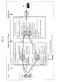
- FIG. 2 shows a configuration of the system including the administrator side as the system (logistics management system for transportation of vehicles) of this embodiment.
- the whole system (logistics management system for transportation of vehicles) has: a vehicle-loading/unloading managing system which is a high-order system 5; the center system 4 (vehicle-position managing system) which is a system for each site (for example, a terminal or an office); and the above HH terminal 1 and the GPS receiver 2 which are connected to the center system.
- Operators (W1 and W2) carry and operate the HH terminal 1 and the GPS receiver 2.
- the high-order system 5 (vehicle-loading/unloading managing system) has software, DB, and the like which carry out processes of managing/supporting vehicle distributing tasks (management of loading/unloading and management of operations), and the system may be an existing system or a unique system.
- the high-order system 5 may be on a network (cloud), or may be in each site as a system integrated with the center system 4.
- the center system 4 (vehicle-position managing system) has at least a vehicle-position managing function, and this system has a PC 3 (vehicle-position managing device).
- the center system 4 is composed of the PC 3 in an office and the like next to a terminal on the site, and this system is operated and used by the administrator U1.
- the PC 3 has a vehicle-position managing function, and has an application 33 (server program) and a GUI function 34 using software program processes operated on a CPU, ROM, RAM, OS and the like (not shown).
- the application 33 (server program) includes a vehicle-position registering function (position-registration processing unit 33A) and a vehicle-position searching function (position-search processing unit 33B).
- the application 33 is linked (communicates) with an application 13 in the HH terminal 1.
- the PC 3 is connected to or incorporates a DB and is connected to or incorporates an output device(s) such as a printer and/or a display and an input device(s) such as a mouse and/or a keyboard.
- the GUI function 34 carries out a process of displaying GUI information on a display screen.
- the HH terminal 1 has a vehicle-position managing function, and has an automatic recognition function 11 (BC reader), a near field wireless communication function 12, an application 13 (client program), and a GUI function 14, each of which is constituted by software programs which are executed on CPU, ROM, RAM, OS, and the like (not shown).
- the application 13 (client program) includes a vehicle-position registering function (position-registration processing unit 13A) and a vehicle-position searching function (position-search processing unit 13B).
- the application 13 is linked (communicates) with the application 33 in the PC 3.
- the HH terminal 1 is provided with: an output device such as a display; and an input device such as key buttons.
- the HH terminal 1 may is provided with a touch panel as a display screen, or a main body thereof may be provided with dedicated buttons.
- the automatic recognition function 11 is a BC reader function which scans the BC 1006 of the medium 1005, and reads vehicle management information (data A) including the VIN (vehicle ID).
- vehicle management information data A
- an OCR (optical character reading) function or a RFID (wireless IC tag) reader function may be used.
- the near field wireless communication function 12 uses a Bluetooth (registered trademark), but may use another method.
- this is a wired communication function if the HH terminal 1 and the GPS receiver 2 are connected to each other with wires.
- the GUI function 34 carries out a process of displaying GUI information on the display screen.
- the HH terminal 1 can be connected to, and can communicate with the GPS receiver 2 (near field wireless communication function 22) by using the near field wireless communication function 12, and can obtain positioning information (data B) from the GPS receiver 2 when needed.
- the GPS receiver 2 near field wireless communication function 22
- data B positioning information
- the GPS receiver 2 has a positioning function 21, the near field wireless communication function 22, and an antenna 23.
- the positioning function 21 carries out GPS positioning by receiving radio waves of the GPS satellite 1003 via the antenna 23, and outputs the GPS positioning information (data B).
- the operator W1 utilizes the application 13 (the position-registration processing unit 13A) of the HH terminal 1 to press a predetermined button and scan the BC 1006 of the medium 1005 of the vehicle 10, thereby obtaining the vehicle management information (data A) including the vehicle ID.
- the vehicle management information (data A) including the VIN and the GPS positioning information (data B) about the target vehicle 10 is obtained/saved in association with each other in a memory in the HH terminal 1. Then, the HH terminal 1 transfers the data A and B to the PC 3 of the center system 4.
- the application 33 (position-registration processing unit 33A) of the PC 3 registers (stores) the data A and B (the information including the ID and the position of the vehicle) in the DB and returns results.
- the operator W1 moves to the vehicle 10 which is a next target, and repeats similar operations (handling).
- the operator W1 utilizes the application 13 (the position-search processing unit 13B) of the HH terminal to input search conditions and carry out a search on the basis of the search conditions.
- the search conditions (request) are transmitted from the HH terminal 1 to the PC 3 of the center system 4.
- the application 33 (position-search processing unit 33B) of the PC 3 carries out search in the DB according to the search conditions and returns results.
- the HH terminal 1 displays the search result on the screen.
- the administrator U1 utilizes the application 33 (position-search processing unit 33B) of the application 33 of the PC 3 to input search conditions and carry out a search on the basis of the search conditions.
- the application 33 (position-search processing unit 33B) of the PC 3 carries out search in the DB according to the search conditions and displays a search result on the screen.
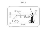
- FIG. 3 schematically shows height comparison of the vehicle 10, the operator W1, the GPS receiver 2, and the like.
- the GPS receiver 2 is elevated above the height h2 of the vehicle 10.
- the vehicle 10 is mostly a metal chunk, and if many vehicles are densely stored, the radio waves from the GPS satellite 1003 are reflected by the vehicles forming a multipath, thereby negatively affecting (lowers) the GPS positioning accuracy.
- the terminal is not provided with GPS function
- the HH terminal and the GPS receiver 2 are mutually separated and linked
- the GPS receiver 2 is attached to the cap 1004 of the operator W1.
- the cap 1004 is a dedicated cap in which a bag housing the GPS receiver 2 is provided at the top (head top part) thereof.
- the GPS receiver 2 may be attached to a part of a back collar or shoulder of the clothing worn by the operator W1 instead of the cap 1004. As a result, similar effects can be obtained.
- the operator W1 who operates the completed vehicle (10) should not wear an object which has a potential to scratch the vehicle, as much as possible. Therefore, although the GPS receiver 2 is desired to be high as possible, it is not possible to, for example, carry a stick-like object on the back of the operator W1, and attach the GPS receiver 2 at the tip thereof.
- the GPS positioning result has errors caused by various factors (for example, received radio wave intensity from the GPS satellite, GPS satellite position, the state of the ionized layer of the earth, and the like at the time of positioning).
- errors are small (for example: about several millimeters to several centimeters); however, it is extremely expensive, and this device is large and heavy in many cases. Furthermore, it takes a long time to carry out positioning of one point (for example: several minutes to several tens of minutes). Because of this, it is not suitable for the vehicle distributing task.
- GPS GPS receiver
- consumer equipment such as car navigation, it is low in price, small, and light. However, its GPS positioning accuracy is affected by errors caused by the above described various factors, and reduced. The positioning error thereof is, for example, several meters to several tens meters.
- the system is designed in a balanced manner by using the low-price device which is used as the GPS receiver 2, and providing a mechanism compensating errors while taking its relatively low GPS positioning accuracy into consideration.
- the GPS in order to register the storage position of a vehicle, for example, the position of each of the vehicles closely-spaced and stored in a terminal is measured by the GPS.
- One vehicle is within the range of a size of, for example, about 2.5 m ⁇ 5 m.
- the positioning error thereof is about several m or less, the mistake that could occur in system registration is only mix-up between an adjacent vehicle and the target vehicle.
- the present system has, for example, a function of correcting the position at the time of vehicle position registration. Therefore, a low-price receiver having a measurement error of about several m to several tens of m can be utilized as the GPS receiver 2 as described above.
- FIG. 4 shows a configuration example of the data information managed in the DB of the center system 4 in the system of FIG. 2 .
- vehicle management information (D1), terminal management information (D2), operation management information (D3), and the like are managed in tables.
- the vehicle ID is information which uniquely identifies the vehicle 10.
- the storage position is information which identifies the place (position) in which the vehicle 10 is stored in the terminal and consists of, for example, a yard ID, an area ID, a location (section) ID, and GPS positioning information (latitude/longitude, coordinate point).
- the status is the information such as vehicle accompanying information, domestic use or exporting (oversea) use, or an operation type.
- the terminal management information (D2) includes map information (map) and location management information.
- the map information (map) includes management information (ID (number), position information, and the like) of each unit such as terminal, yard, area, or parking area described later ( FIG. 5 ).
- the map information may be obtained by utilizing, for example, an existing map service (data).
- the location management information includes management information of a location (section). In the location management information, an ID, a position (the coordinate of a representative point), a size, and the like are managed in the unit of the location (section) described later ( FIG. 6 ).
- the operation management information (D3) has: an operator (ID, name, and the like), operation instructions (for example, movement origin position, destination position), an operation state (for example, loading, movement (shirt), unloading, and the like), an operator position, and the like.
- the positioning information (the positioning information at the time of vehicle position registration and periodic positioning information) by the GPS receiver 2 can be utilized as the operator position.
- an operator who started an operation, a HH terminal which was used in that operation, and start time of that operation can be understood by pasting a barcode or the like representing an operator ID or the like on a nameplate (ID card or the like) of each operator (for example, W1) and reading the ID with the HH terminal 1 of the operator at the time of start of the operation.
- the HH terminal 1 of the operator may be configured to automatically/periodically (for example, every one minute) obtain the position of the operator (HH terminal 1) by positioning using the GPS receiver 2 and transmit/register the position to the system (DB).
- DB the position of the operator
- the motion line of the operator can be understood, and this can be utilized for optimization of the task.
- the positioning information (data B) obtained by the GPS receiver 2 is transmitted in a NMEA format which includes accompanying information such as for example latitude/ longitude information, the number (M) of the GPS satellites used in the positioning at that time, and HDOP (N).
- the present system (DB) stores various set values (for example, threshold values m1 and m2 of the number (M) of the GPS satellites and a threshold value n of HDOP (N) described later).
- the high-order system 5 (vehicle-loading/unloading managing system) is designed to manage loading/unloading information for vehicles, and issue an operation instruction list of loading/unloading (with no location management) to the center system 4.
- the center system 4 (vehicle-position managing system) is designed to receive the loading/unloading operation instruction list (with no location management) from the high-order system 5.
- the PC 3 is designed to convert it to information in a format supporting the location management of this embodiment. Additionally, the conversion may be carried out in the high-order system 5. Then, on the basis of the loading/unloading operation instruction list (with location management), the center system 4 (PC 3) is designed to issue an operation instruction from the administrator U1 to, for example, the operator W1.
- FIG. 5 shows a configuration example of the map (terminal).
- This terminal T0 automobile (completed vehicle) terminal
- This terminal T0 is an outdoor land serving as a storage space for vehicles 10 (particularly, completed vehicles is kept until shipment after manufacturing) for vehicle distributing operation.
- Terminal in place of the term “terminal”, it is referred to as "warehouse”, "distribution center” and the like.
- Cargo (load) is vehicles 10.
- loading (arrival) and unloading (shipment) from the terminal T0 will be described.
- the vehicle (completed vehicle) 10 transported (moved) from a loading origin such as factory or another terminal is loaded (arrival, receiving) into the terminal T0 and stored (parked, kept).
- the vehicle 10 stored in the terminal T0 is carried out (picked and the like) for transportation to a delivery destination (transportation destination) and unloaded (shipped).
- the vehicle is moved from the terminal T0 to a dock or the like for loading onto a ship.
- transportation means ship, trailer and the like is used.
- the vehicles are moved by drivers in the terminal T0.
- a first yard Y1 is a receiving/storing yard mainly used in loading.
- a second yard Y2 is a hoisting yard mainly used for unloading. Additionally, not only completed vehicles, but also in-process vehicles and the like may be stored.
- the terminal T0 can be separated into particular areas.
- examples of the areas include: areas for respective loading origins, areas for respective vehicle types, areas for respective delivery destinations, and areas for respective unloading dates.
- information on vehicle storage position and the like is registered in the system (DB).
- information on the vehicle storage position is searched from registered information of the system (DB) to look-up (find) the target vehicle to move the vehicle. Also in a case where the storage position is changed (shifted) in the terminal T0, the position is appropriately searched/registered.
- position registration position management
- the configuration is not limited to that of the present example, and a plurality of terminals, yards, areas, and the like can be hierarchically provided.
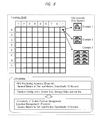
- FIG. 6 shows one configuration example of allocation of locations (grid).
- this system the center system 3 (PC 3) and the HH terminal 1
- location management or free location management of the vehicles 10 in the terminal T0 (map) is carried out. Therefore, in this figure, the configuration example of the locations allocated to the map (terminal T0) is shown.
- This is a configuration of grids (matrix-like sections).
- One ID location ID
- One ID is imparted to one location corresponding to a square section.
- one location is represented by "A-1”.
- the storage position of the vehicle 10 is managed by the unit (ID) of the location (section) together with the GPS positioning information.
- ID unit
- the granularity of the vehicle position management corresponds to the granularity of the location management.
- a suitable location configuration is designed depending on the GPS positioning accuracy, terminal configuration, vehicle size, storage rules of each site, and the like. It is designed also in consideration of average storage space for vehicle (by taking into ease of operation into consideration), the size of each parking area (parking reference lines) formed on the road surface, and the like.
- the size of each square location is 5 m ⁇ 5 m.
- the ratio of one location to the number of vehicles is 1:1.
- one vehicle 10 is stored in one location.
- the average storage space for each vehicle is 5 m ⁇ 5 m (larger in size than vehicle and enough for storage of vehicle).
- the size of one location is 5 m ⁇ 5 m, and the ratio of one location to the number of vehicles is 1:2 (two vehicles 10 are stored in one location).
- the average storage space for each vehicle is 2.5 m ⁇ 5 m, which is the same in size as the vehicle.
- the size of one location is 10 m ⁇ 10 m, the ratio of one location to the number of vehicles is 1:8, and eight vehicles 10 are stored in one location.
- the GPS positioning accuracy (positioning error) by the GPS receiver 2 is, for example, several m to 10-odd meters (here, in order to facilitate understanding, particularly assumed to be 10 m in order to facilitate understanding). It is assumed that the average size of one vehicle is 2.5 ⁇ 5 m.
- the granularity of location management is equivalent (several m to 10-odd m (particularly 10 m)) to the GPS positioning accuracy (positioning error) (above described third example).
- the granularity of location management suitably employs the unit of some grouped vehicles instead of the unit of each vehicle (above described first example) since the GPS positioning accuracy is, for example, several meters or more (particularly 10 m). Therefore, for example, the above described third example is employed.
- the granularity of the vehicle position management (location management) is 10 m corresponding to the size of the section.
- the configuration is not limited to the above described configuration examples, and other location configurations (design) can be also employed.
- the granularity of the vehicle position management (location management) is larger than that of the GPS positioning accuracy, errors in position registration are reduced.
- space utilization efficiency can be improved. It can be designed with a necessary balance in consideration of prioritized effects.
- the present system may be configured to be provided with a function capable of variably setting (adjusting) the granularity (location configuration) of the above described location management. In that case, the balance can be adjusted depending on the characteristics of sites.
- the vehicle storage positions in the terminal T0 basically become free (arbitrary in vacant locations), operation time can be shortened, space utilization efficiency is improved, and increase/decrease in the number of stored vehicles can be easily adapted.
- the location management is carried out by using the simple grid structure, but may be carried out on the basis of the structure of the location (section) corresponding to the shape of the map (terminal). For example, locations are set to match parking areas which are discontinuously present on the road surface. In that case, the calculations for associating become complex, but the positions of registration of the vehicles become easily distinguishable.
- FIG. 7 shows an example of association between the parking areas (1007) and locations (sections) in the map (terminal TO).
- one parking area one vehicle
- one location section
- two parking areas two vehicles
- a plurality for example, 8) parking areas (vehicles) are managed in connection with one location (section).
- the stored vehicles in one location (section) are managed (registered) by the same location ID.
- each vehicle can be found as a pinpoint at the time of position search. Instead, each location (section) is relatively small, and the required GPS positioning accuracy is needed.
- each location (section) is relatively large, and the required GPS positioning accuracy can be relatively suppressed low (low-price GPS receiver 2 can be utilized).
- the target vehicle if a vehicle in one location (section) is to be looked up (position search), the target vehicle cannot be found as a pinpoint; however, when the operator goes to the section of the location ID, the vehicle is certainly present in the at most eight vehicles therein, and the target vehicle can be therefore easily found since there are about eight vehicles.
- FIG. 8 shows examples of parking areas and storage rules in the map (terminal TO). These are conventionally existing examples, but can be also supported by the present system.
- parking reference lines there is a plurality of parking areas (parking reference lines) (802) sectioned by a road (801), and parking area numbers (803) and the like for identification are applied on the road surface. In some cases, vehicles are temporarily stored also on the road (801).
- vehicles are loaded on a ship, and in this case, vehicles are closely-spaced and stored in parallel parking in a single direction in parking areas (811).
- vehicles are loaded on a trailer, and three vehicles and three vehicles are stored so as to face each other.
- vehicles may be stored in an orderly manner under certain rules in each parking area.
- vehicles may be stored so that their right tires are disposed on a line of a parking area.
- vehicles in an area (for example (b)) in which a plurality of vehicles are parked, vehicles may be closely- spaced and parked in a parallel parking manner as much as possible.
- FIG. 9 shows an example of storage, operation, and the like in the terminal T0.
- the vehicles (completed vehicles) 10 are loaded from, for example, an exit of an adjacent factory.
- the operator W1 carries out position registration, and a location ID corresponding to the storage position is, for example, A-1.
- the operator W1 carries out position registration, and a location ID corresponding to the storage position is, for example, B-1.
- the areas A1 and A2 of the yard Y1 are, for example, areas for respective vehicle types.
- the vehicles may be stored at free positions, or may be stored in an orderly manner roughly in each area.
- the storage positions of the vehicles can be arbitrarily moved (shifted) if there is allowance.
- the vehicles are only moved from the first yard Y1 to the second yard Y2 at the timing of unloading determination.
- the second yard Y2 has, for example, areas B1 and B2 respectively for delivery destinations. The efficiency of the operations is improved when the vehicles are stored in the areas respectively which are for the delivery destinations.
- the target stored vehicles in the first yard Y1 are moved (shirted, picked, hoisted) to the area, which are for respective delivery destinations, in the second yard Y2.
- the storage positions after the movement are similarly registered. If position management becomes unnecessary at this point, the position registration can be omitted. For example, if they are stored in the area for each delivery destination because of unloading determination, position registration is unnecessary since the positions thereof are clear (look-up is easy).
- the operations in the terminal T0 are sometimes shared by a plurality of operators.
- there are two operators including the first operator W1 who carries out position registration, and the second operator W2 who is in charge of moving vehicles by driving.
- the administrator U1 of the center system 4 carries out overall operation management, and instructs the operators W1 to carry out operations.
- FIG. 10 shows an operation flow for loading.
- a vehicle 10 carried from a loading origin such as a factory is stored in the yard Y1 in the terminal T0.
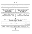
- FIG. 11 shows a flow of the case B in the above described operation flow for loading.
- the vehicle is firstly stored by the first operator W1 who does not have the devices 1 and 2, position registration is then carried out by the second operator W2 by using the devices 1 and 2.
- Reference characters "B1" and "B2" represent the presence/absence of the instruction on the rough storage place as well as the above case.
- FIG. 12 shows an operation flow for unloading.
- the vehicle before unloading (loading onto a ship) a target vehicle, the vehicle is once moved (shifted) from the first yard Y1 (area of a storage place at the time of loading) into the second yard Y2 (area for, for example, each delivery destination) and stored.
- the first yard Y1 area of a storage place at the time of loading
- the second yard Y2 area for, for example, each delivery destination
- step S2 the administrator U1 can search the information such as the storage position of the target vehicle by carrying out a process using the position searching function 33B of the application 33 of the PC 3.
- the detailed storage position of the vehicle can be found out by inputting a vehicle ID and the like as search conditions and executing a search.
- the information obtained in the search may be added to the operation sheet.
- the flow of C2 is as follows.
- position management is not needed after storage in the yard Y2
- position registration using the devices (1 and 2) is not carried out.
- areas are clearly separated, for example, for delivery destinations or for shipment date in the yard Y2.
- position registration is not carried out, the HH terminal 1 may be used, for example, for position search or display of operation instructions.
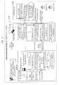
- FIGS. 2 and 13 A basic processing flow of the position registering function in the system of this embodiment will be explained with reference to FIGS. 2 and 13 .
- the explanation will be given for the case in which the HH terminal 1 (application 13) is operated by the operator W1.
- the PC 3 (application 33) may be operated by the administrator U1, and it can be similarly carried out.
- a process of a later-described filtering (re-positioning) function ( FIG. 18 ) and/or a process of the correction function ( FIG. 19 ) may be inserted.
- directions may be set, or the direction in which the operator is going may be selected and set to match that on the screen.
- latitude/longitude information (coordinate point on a map) or the like according to the GPS positioning information (data B) may be registered without being changed, information in the unit of a location or the like calculated from the latitude/longitude information may be registered, or both of them may be registered in association with each other.
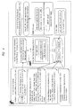
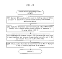
- FIGS. 2 and 14 A basic processing flow of the position searching function in the system of this embodiment will be explained with reference to FIGS. 2 and 14 .
- the explanation is given for the case in which the HH terminal 1 (application 13) is operated by the operator W1.
- the PC 3 (application 33) is operated by the administrator U1, it can be similarly carried out.
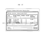
- FIG. 15 shows an output example 1 at the time of position search.
- information at the time of position search is displayed together with operation instructions on the display screen of the PC 3 by the administrator U1.
- Information similar to this may be displayed on the screen of the HH terminal 1, or may be printed on paper (operation sheet) by a printer. Similar output can be carried out also at the time of position registration.
- the administrator U1 creates and displays an operation sheet on the basis of a list of the above described loading/ unloading operation instructions by the PC 3.
- VIN vehicle ID
- storage place position
- attribute state
- state delivery destination
- the storage place position
- attribute is, for example, delivery destination.
- the state is, for example, operation type (operation state) (for example, loading/shifting/unloading).
- the "delivery destination" represents the place (yards area and the like) of vehicle in the operation instruction.
- the row of 1501 shows that: the current storage place of a vehicle having a certain VIN is "yard Y1, area A2, location E-5"; the delivery destination is "A”; the operation type is “unloading operation”; and the destination is "yard Y2, area B1" (corresponding to the example of FIG. 9 ).
- the administrator U1 selects, for example, a target VIN in the screen (example: 1501) and presses a search button (or executes a search command).
- a search button or executes a search command.
- the above described process of the position search is executed, and the search result is displayed on the screen.
- a search condition such as VIN may be input in a search condition field, and the search button may be pressed.
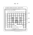
- FIG. 16 shows an output example 2 at the time of position search. This is an example in which the information of the storage position of the search result on the map is displayed on the display screen of the PC 3 at the time of position search. Information similar to this may be displayed on the screen of the HH terminal 1 or may be printed on paper (operation sheet) by a printer. Similar output can be carried out also at the time of position registration.
- the above described location (grid) ( FIG. 6 ) is overlapped and displayed on a map.
- the map when it has data (image) of yard, area, parking area, and the like, they are displayed in combination.
- 1601 is an example of a vehicle storage position (location) of a search result. It shows in which location the target vehicle is stored (registered). For example, the frame, coordinate point, or the like of the location is displayed in an intensified manner by, for example, red.
- 1602 shows a case in which relevant information (for example, VIN, storage position, and destination) is displayed by, for example, a pop-up.
- the administrator U1 may transfer the information of the search result to the HH terminal 1 of the operator W1, or may print the information on paper (1008) and pass it to the operator W1.
- the operator W1 may look-up the target vehicle while seeing the information (operation instruction information 1008) of the search result by the screen of the application 13 of the HH terminal 1, or may look it up while seeing the paper (1008). By virtue of this, the vehicle can be easily found in a short period of time.
- this system has a function of guiding by displaying various information on the screen (GUI). Even if such a function is not provided, minimally, only a function of outputting the values of the area and location corresponding to the position of the target vehicle may be provided. As long as the operator W1 understands the outline of the configuration of the areas and locations in the terminal T0 by a paper map or the like, it can be looked up sufficiently in a short period of time.
- a route from the current position of the operator (according to GPS) to the position of the target vehicle may be displayed on the screen. Also, a route from the current storage position to the storage position of the destination may be displayed on the screen.
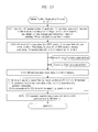
- FIG. 17 shows screen examples of a case in which a GPS positioning result is displayed on the screen so that the operator W1 can carry out correction at the time of position registration by the position registering function (including the later-described filtering function and correction function) by using the HH terminal 1.
- the example (a) shows the screen before the correction
- the example (b) shows the screen after the correction.
- the screen of the shows the information of a positioning result (correction) as shown in FIG. 17 .
- the operator W1 manually moves the positioning point (a1) of the present time in the screen to a position estimated to be actually correct according to the information in the screen and the actual state.
- the positioning point a3 is the nearest from the point (position) of a1 and is the position estimated to be actually correct according to the previous positioning results (a2) in that neighborhood and the state, and the frame of a4 is a parking area corresponding to a3.
- the operator W1 manually moves the point of a1 to the position of a3 (a4) as shown by an arrow of a5.
- This movement may be, for example, top/bottom/left/right operations of a key button or the like or may be a touching operation (dragging) on a touch-panel screen depending on the specifications of the HH terminal 1. Then, the operator W1 can carry out position registration by pressing the determination button at the position (a3, a4) after the movement (correction).
- the correction is not limited to the above described manual correction, but an automatic correction function may be provided.
- the present application 13 compares the point (a1) of the positioning result of the present time and the points (a2) of the previous positioning results in that neighborhood with each other, calculates the position estimated to be actually correct like a3 (a4), and displays that as an option of position registration.
- the operator W1 sees the option like a3 (a4); and, if the operator determines it is appropriate, position registration can be carried out by selecting it or by the determination button.
- an automatic correction button may be prepared so that, when the operator W1 presses the automatic correction button, automatic correction to the option position is carried out in the above described manner.
- positioning may be carried out again by pressing a re-positioning button so that the result thereof is displayed.
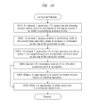
- the application 13 of the HH terminal 1 (the corresponding application 33 of the PC 3) has the filtering function (re-positioning function).
- the flow of FIG. 18 is added to the flow of FIG. 13 .
- This function also corresponds to the re-positioning function of the screen of FIG. 17 .
- This filtering function is a function that evaluates/determines the positioning result (data B) obtained with relatively-low GPS positioning accuracy, carries out filtering (discarding, rejection) if inappropriate in order to take a measure against a positioning error, and carries out re-positioning. By virtue of this, a low-price receiver can be easily employed as the GPS receiver 2.
- FIG. 18 shows a processing flow of the filtering function (re-positioning function). It has predetermined characteristic determination step (S303) and the like.
- the number of GPS satellites M and “HDOP” (N) in the NMEA format of the GPS positioning information (data B) are used.
- the “number of GPS satellites” is the number of the GPS satellites utilized at the time of positioning, and has a high correlation with positioning accuracy.
- the “HDOP” is one of positioning accuracy indexes, and is DOP (Dilution of Precision) in the horizontal direction, wherein, the more densely satellites are distributed up in the sky, the more smaller the HDOP value becomes.
- the number of GPS satellites (M) and the HDOP (N) are used as evaluation values.
- the above described evaluation values (M, N) are compared with threshold values.
- the threshold values of the number of the GPS satellites (M) are "m1" and “m2" (m1>m2), and the threshold value of HDOP (N) is "n".
- the threshold values can be variably set in this system.
- the number of the GPS satellites (M) is equal to or less than "m2”, the result is rejected (NG) like S305.
- the result is employed (OK).
- m2 5.
- the second determination method when the positioning accuracy is not too low or not is determined.
- both of the above described first and second determination methods may be used in combination. Only the number of the GPS satellites (M) may be used to carry out determination, or only HDOP (N) may be used to carry out determination. Other element values in the format of the GPS positioning information may be used in combination.
- the above described evaluation values of the accuracy (the number of the GPS satellites (N), HDOP (N)) or information thereof expressed in a different way (for example, a message showing the magnitude of the accuracy) may be displayed in the screen of the HH terminal 1. For example, the information may be always displayed.
- the operator W1 sees the evaluation values (M, N) displayed on the screen, determines whether or not the positioning accuracy (positioning error) is appropriate according to the magnitude, and determines to employ or reject the result. If employed, for example, the determination button is pressed. If rejected, for example, the re-positioning button is pressed to do it again.
- the application 13 of the HH terminal 1 (the corresponding application 33 of the PC 3) has a correction function.
- the flow of FIG. 19 is added to the flows of FIGS. 13 and 18 . Additionally, this function corresponds to the function of manual correction or automatic correction of the screen of FIG. 17 .
- FIG. 19 shows a flow chart of the correction function. This flow has a predetermined characteristic correction step (S405) and like.
- the decision is made on the basis of the setting of this system.
- the transition may be certainly made once automatically before the data A and B is transmitted to the center system 4, or the transition may be made under predetermined conditions or by a predetermined user operation.
- the operator W1 does not want to carry out correction
- the operator can proceed to a next operation without doing anything except for checking (for example, the determination button).
- the transition is made only when the positioning error is large according to the evaluation value such as the above described number of the GPS satellites (M).
- the position registering function correction function
- the position registering function correction function
- the efficiency of the operations such as registration and look-up (search) of the places (positions) of the vehicles in the terminal at the time of loading/unloading can be improved (for example, simplified, the time taken therefor can be shortened).
- the system can be realized at low cost with sufficient management accuracy (for example, GPS positioning accuracy) supporting the characteristics of sites.
- sufficient management accuracy for example, GPS positioning accuracy
- reduction in the lead time from unloading determination to unloading completion can be realized.
- the free location management the stored positions of the vehicles in the terminal are liberalized to some extent so that space utilization efficiency can be improved, look-up (search) can be facilitated, and the time taken therefor can be shortened.
- This embodiment has a configuration in which the HH terminal 1 and the GPS receiver 2 are separated from and linked with each other, and the positioning accuracy can be improved by placing the low-price GPS receiver 2 at a position higher than the vehicle 10 to reduce the influence of reflection.
- a series of processes including obtainment and registration of the vehicle ID and positioning information can be carried out by one operation (for example, one button), wherein the operation of scanning the BC 1006 serves as a trigger. Therefore, the operation is easy and also effective for preventing registration from being forgotten. Furthermore, in connection with position search, positions are graphically displayed on the screen, and it is easy to carry out look-up.
- a low-cost system By utilizing the low-price/small/light-weight GPS receiver 2, a low-cost system can be built. Furthermore, the mechanisms (for example, filtering function, correction function) which compensate for the relatively-low GPS positioning accuracy of the low-price GPS receiver are provided. By virtue of this, the accuracy of position registration and search is improved (sufficient management granularity is realized), and the time taken for operations can be shortened. If the accuracy (granularity) is desired to be further improved, a system using a GPS receiver having high positioning accuracy can be also built.
- the filtering function and the correction function when the positioning information obtained by the GPS receiver 2 is to be used in position registration, inappropriate results caused by positioning errors can be eliminated/corrected by utilizing determination by a person (operator W1), and more appropriate positioning information can be utilized as a result of re-positioning/correction.
- the accuracy of position registration can be enhanced by effectively utilizing determination by a person about, for example, the actual state in that neighborhood.
- the information of the positioning accuracy (evaluation value) such as the number of the GPS satellites (M) is displayed in the screen; therefore, the operator W1 can roughly understand the positioning accuracy at the time of position registration.
- the positioning accuracy is the predetermined threshold value, it is rejected, and re-positioning can be automatically executed. Therefore, the accuracy of position registration can be improved as much as possible.
- the tasks (operation) of storing vehicles are often carried out under extremely orderly rules (storage rules) compared with, for example, general parking space.
- the storage rules include several ways as described above ( FIG. 8 ).
- the position of the positioning result is plotted on the screen of the HH terminal 1 of the operator together with the positions of the previous positioning results in that neighborhood. Therefore, while using the information in the screen as a guide, the operator can visually determine whether the position of the positioning result to be registered this time is how much displaced from or matching the actual storage position (for example, parking area).
- the HH terminal 1 of the operator W1 may be provided with a photographing function (for example, a device such as camera may be utilized) as another function.
- a photographing function for example, a device such as camera may be utilized
- the photograph data is obtained/saved.
- the photograph data is transferred to, for example, the center system 4, and saved in association therewith in the DB.
- the above described position registration (transfer of the data A, B) can be carried out by one trigger operation; wherein, an option of transfer of the photograph data is additionally provided for that so that the option can be selected and executed.
- the photograph data can be utilized, for example, in a maintenance operation of the vehicle thereafter.
- the BC 1006 is configured to be read; however, the object is not limited thereto, and, for example, a RFID (IC tag) can be utilized (for example, a corresponding RFID reader/writer function is used).
- a RFID IC tag
- the above described operation of position registration should be carried out near the RFID, and the vehicle ID and the like can be more easily read.
- the RFID is pasted, for example, on the front of the vehicle or a left/right window in the form of a label. For example, the RFID is latched and hung from an attachment column of a rear-view mirror in the vehicle. As a result, the RFID can be reused, and the information of the RFID in the vehicle can be read from outside of the vehicle.
- the present invention accomplished by the present inventor is explained in detail on the basis of the above embodiment, the present invention is not limited to the above embodiment, and it goes without saying that various modifications can be made without departing from the gist thereof.
- the invention can be applied not only to position management of vehicles, but also to position management of goods in a similar terminal (outdoor land).
- the present invention can be utilized in a task of distributing mainly vehicles. Also, the present invention can be utilized in a case in which many large steel materials are temporarily stored in a huge plot of land in order to carry out assembling operations.
Landscapes
- Business, Economics & Management (AREA)
- Economics (AREA)
- General Physics & Mathematics (AREA)
- Physics & Mathematics (AREA)
- Engineering & Computer Science (AREA)
- Marketing (AREA)
- Quality & Reliability (AREA)
- Finance (AREA)
- Entrepreneurship & Innovation (AREA)
- Human Resources & Organizations (AREA)
- Accounting & Taxation (AREA)
- Operations Research (AREA)
- Development Economics (AREA)
- Strategic Management (AREA)
- Tourism & Hospitality (AREA)
- General Business, Economics & Management (AREA)
- Theoretical Computer Science (AREA)
- Management, Administration, Business Operations System, And Electronic Commerce (AREA)
- Traffic Control Systems (AREA)
- Warehouses Or Storage Devices (AREA)
Applications Claiming Priority (2)
| Application Number | Priority Date | Filing Date | Title |
|---|---|---|---|
| JP2012184069A JP5377726B1 (ja) | 2012-08-23 | 2012-08-23 | 車両物流管理システム |
| PCT/JP2013/057669 WO2014030374A1 (ja) | 2012-08-23 | 2013-03-18 | 車両物流管理システム |
Publications (2)
| Publication Number | Publication Date |
|---|---|
| EP2889234A1 true EP2889234A1 (de) | 2015-07-01 |
| EP2889234A4 EP2889234A4 (de) | 2016-02-10 |
Family
ID=49955012
Family Applications (1)
| Application Number | Title | Priority Date | Filing Date |
|---|---|---|---|
| EP13831478.6A Ceased EP2889234A4 (de) | 2012-08-23 | 2013-03-18 | Managementsystem für fahrzeuglogistik |
Country Status (6)
| Country | Link |
|---|---|
| EP (1) | EP2889234A4 (de) |
| JP (1) | JP5377726B1 (de) |
| IN (1) | IN2015DN01012A (de) |
| MX (1) | MX2015002383A (de) |
| PH (1) | PH12015500352B1 (de) |
| WO (1) | WO2014030374A1 (de) |
Cited By (1)
| Publication number | Priority date | Publication date | Assignee | Title |
|---|---|---|---|---|
| US12099956B2 (en) | 2020-02-24 | 2024-09-24 | Coupang Corp. | Operation method for location recommendation and apparatus therefor |
Families Citing this family (17)
| Publication number | Priority date | Publication date | Assignee | Title |
|---|---|---|---|---|
| JP6541959B2 (ja) * | 2014-12-01 | 2019-07-10 | Eclエージェンシー株式会社 | 車両管理システム |
| JP6149894B2 (ja) * | 2015-04-27 | 2017-06-21 | 沖電気工業株式会社 | 位置情報処理装置及びプログラム、並びに位置情報処理システム及び位置情報処理方法 |
| JP6534572B2 (ja) * | 2015-07-16 | 2019-06-26 | 国立大学法人九州大学 | 蔵置位置決定方法及び蔵置位置管理システム |
| EP3395725A4 (de) * | 2015-12-22 | 2019-06-19 | Nippon Yusen Kabushiki Kaisha | Managementsystem für fahrzeuglogistik |
| US11507918B2 (en) | 2017-04-13 | 2022-11-22 | Surgere, Llc | Automotive asset location management systems and methods |
| JP6795473B2 (ja) * | 2017-08-29 | 2020-12-02 | 富士通フロンテック株式会社 | オークション出品中古車駐車位置管理装置、およびオークション出品中古車駐車位置管理方法 |
| JP6953345B2 (ja) * | 2018-03-28 | 2021-10-27 | 株式会社日立ソリューションズ・クリエイト | 貨物ダメージ情報管理システム、及びそれに用いる貨物ダメージ情報管理方法 |
| EP3776513A4 (de) * | 2018-04-11 | 2021-12-15 | Surgere, Inc. | Systeme und verfahren zur verwaltung des standorts von kfz-beständen |
| CN109693950A (zh) * | 2018-12-25 | 2019-04-30 | 青岛港国际股份有限公司 | 自动化码头卸船作业堆场派位方法和系统 |
| JP2019169194A (ja) * | 2019-06-12 | 2019-10-03 | Eclエージェンシー株式会社 | 車両管理システム |
| JP2021012548A (ja) * | 2019-07-05 | 2021-02-04 | トヨタ自動車株式会社 | 情報処理装置 |
| CN110404830B (zh) | 2019-08-19 | 2021-02-05 | 北京极智嘉科技有限公司 | 分拣系统及方法 |
| JP6894492B1 (ja) * | 2019-12-20 | 2021-06-30 | Jfeスチール株式会社 | 出荷物位置管理システム、及び出荷物位置管理方法 |
| JP7435074B2 (ja) * | 2020-03-13 | 2024-02-21 | オムロン株式会社 | 複数の装置を制御するシステムおよび方法 |
| JP7521389B2 (ja) * | 2020-11-25 | 2024-07-24 | 積水ハウス株式会社 | 地図生成装置 |
| JP7613922B2 (ja) * | 2021-01-18 | 2025-01-15 | 日立建機株式会社 | 測位精度出力システム及びそのサーバ装置 |
| JP7714408B2 (ja) * | 2021-09-03 | 2025-07-29 | Toppanエッジ株式会社 | 駐車管理システム、駐車管理方法および情報処理装置 |
Family Cites Families (12)
| Publication number | Priority date | Publication date | Assignee | Title |
|---|---|---|---|---|
| JP2001175983A (ja) * | 1999-12-22 | 2001-06-29 | Nec Mobile Commun Ltd | 顧客データ登録システムおよび顧客データ登録方法 |
| JP2001348110A (ja) | 2000-06-09 | 2001-12-18 | Ntt Advanced Technology Corp | 携帯端末を用いる物流管理方法及びシステム |
| US6356802B1 (en) * | 2000-08-04 | 2002-03-12 | Paceco Corp. | Method and apparatus for locating cargo containers |
| CA2423586A1 (en) * | 2000-09-22 | 2002-03-28 | Weatherford/Lamb, Inc. | Methods and apparatus for interactive communications |
| JP3904967B2 (ja) * | 2002-04-19 | 2007-04-11 | 三菱電機インフォメーションシステムズ株式会社 | シャーシー管理システム及びシャーシー管理サーバ及び及びプログラムを記録したコンピュータ読み取り可能な記録媒体及びプログラム |
| JP4281418B2 (ja) * | 2003-05-30 | 2009-06-17 | トヨタ自動車株式会社 | 車両配送管理システムおよび車両配送管理方法 |
| US7646336B2 (en) * | 2006-03-24 | 2010-01-12 | Containertrac, Inc. | Automated asset positioning for location and inventory tracking using multiple positioning techniques |
| FI118394B (fi) * | 2006-05-26 | 2007-10-31 | Savcor One Oy | Järjestelmä ja menetelmä GPS-laitteen paikantamiseksi |
| JP2008087953A (ja) * | 2006-10-05 | 2008-04-17 | Techno Front Kk | 誘導管理システム、管理装置、携帯端末、誘導管理方法、誘導管理プログラムおよびこのプログラムを記録した記録媒体 |
| JP2008143658A (ja) * | 2006-12-11 | 2008-06-26 | Mitsubishi Electric Corp | 位置管理システム |
| JP2009012975A (ja) * | 2007-07-09 | 2009-01-22 | Toshiba Plant Systems & Services Corp | 物品・機材管理システム |
| JP5424465B2 (ja) * | 2009-05-08 | 2014-02-26 | 日昭電器株式会社 | 物品移送ケース、物品移送状況管理方法及び管理サーバ |
-
2012
- 2012-08-23 JP JP2012184069A patent/JP5377726B1/ja not_active Expired - Fee Related
-
2013
- 2013-03-18 IN IN1012DEN2015 patent/IN2015DN01012A/en unknown
- 2013-03-18 WO PCT/JP2013/057669 patent/WO2014030374A1/ja not_active Ceased
- 2013-03-18 EP EP13831478.6A patent/EP2889234A4/de not_active Ceased
- 2013-03-18 MX MX2015002383A patent/MX2015002383A/es active IP Right Grant
-
2015
- 2015-02-18 PH PH12015500352A patent/PH12015500352B1/en unknown
Cited By (1)
| Publication number | Priority date | Publication date | Assignee | Title |
|---|---|---|---|---|
| US12099956B2 (en) | 2020-02-24 | 2024-09-24 | Coupang Corp. | Operation method for location recommendation and apparatus therefor |
Also Published As
| Publication number | Publication date |
|---|---|
| PH12015500352B1 (en) | 2021-03-19 |
| MX2015002383A (es) | 2015-10-05 |
| JP5377726B1 (ja) | 2013-12-25 |
| PH12015500352A1 (en) | 2015-04-20 |
| JP2014040317A (ja) | 2014-03-06 |
| WO2014030374A1 (ja) | 2014-02-27 |
| IN2015DN01012A (de) | 2015-06-26 |
| EP2889234A4 (de) | 2016-02-10 |
Similar Documents
| Publication | Publication Date | Title |
|---|---|---|
| EP2889234A1 (de) | Managementsystem für fahrzeuglogistik | |
| CA2693011C (en) | Information transmission and processing systems and methods for freight carriers | |
| US9127945B2 (en) | Systems and methods for managing a cargo transaction | |
| CN107871175B (zh) | 一种车货匹配派单方法及装置 | |
| EP4323302A1 (de) | Systeme und verfahren zur unterstützung eines kranführers | |
| JP6514360B2 (ja) | 車両物流管理システム | |
| US20200130833A1 (en) | Systems, methods, and devices for package delivery using unmanned aerial vehicles | |
| US20060106742A1 (en) | System and method for weighing and tracking freight | |
| US20120209787A1 (en) | Computerized system and method for matching freight vehicles and loads | |
| US10296855B2 (en) | System and method for managing waste services | |
| JP6133682B2 (ja) | コンテナターミナルにおける海運貨物運送支援システム | |
| JP2005082349A (ja) | コンテナクレーン作業管理システム、コンテナクレーン作業管理方法、及びコンテナクレーン | |
| US20160320191A1 (en) | Data processing device, program, recording medium, and data processing method for assisting formulation of bunkering plan of ship | |
| CN214795962U (zh) | 生产管理系统 | |
| JP2022178591A (ja) | 運行計画作成装置、運行システムおよび運行計画作成装置用のプログラム | |
| CN117908546B (zh) | 基于物联网叉车视觉感知仓库货柜定位的方法 | |
| CN113935675B (zh) | 一种仓储物流运输车辆的装载防错系统及其方法 | |
| EP4372637A1 (de) | System und verfahren darin zur zuweisung eines umwelteinflusses auf massenaushubprojekte | |
| CN208271229U (zh) | 一种物流车辆调度系统 | |
| JP2023117204A (ja) | 情報処理装置及び情報処理方法 | |
| JP2025054564A (ja) | 情報処理方法、情報処理装置およびプログラム | |
| CN117455336A (zh) | 一种基于数字货运的运输可视化管理方法、系统及装置 | |
| JP2023143441A (ja) | サーバ装置、システム、及びシステムの動作方法 | |
| JP2022127227A (ja) | 搬送業務支援システム、搬送業務支援システム用の車載器および搬送業務支援プログラム |
Legal Events
| Date | Code | Title | Description |
|---|---|---|---|
| PUAI | Public reference made under article 153(3) epc to a published international application that has entered the european phase |
Free format text: ORIGINAL CODE: 0009012 |
|
| 17P | Request for examination filed |
Effective date: 20150216 |
|
| AK | Designated contracting states |
Kind code of ref document: A1 Designated state(s): AL AT BE BG CH CY CZ DE DK EE ES FI FR GB GR HR HU IE IS IT LI LT LU LV MC MK MT NL NO PL PT RO RS SE SI SK SM TR |
|
| AX | Request for extension of the european patent |
Extension state: BA ME |
|
| DAX | Request for extension of the european patent (deleted) | ||
| RA4 | Supplementary search report drawn up and despatched (corrected) |
Effective date: 20160111 |
|
| RIC1 | Information provided on ipc code assigned before grant |
Ipc: B65G 61/00 20060101ALI20160104BHEP Ipc: G06Q 50/28 20120101ALI20160104BHEP Ipc: B65G 63/00 20060101ALI20160104BHEP Ipc: G06Q 10/08 20120101ALI20160104BHEP Ipc: B65G 1/137 20060101AFI20160104BHEP Ipc: G08G 1/13 20060101ALI20160104BHEP |
|
| STAA | Information on the status of an ep patent application or granted ep patent |
Free format text: STATUS: EXAMINATION IS IN PROGRESS |
|
| 17Q | First examination report despatched |
Effective date: 20170222 |
|
| REG | Reference to a national code |
Ref country code: DE Ref legal event code: R003 |
|
| STAA | Information on the status of an ep patent application or granted ep patent |
Free format text: STATUS: THE APPLICATION HAS BEEN REFUSED |
|
| 18R | Application refused |
Effective date: 20180906 |