EP2889364A1 - Verfahren und vorrichtung zur erzeugung von methan und zur beseitigung von kohlendioxid - Google Patents
Verfahren und vorrichtung zur erzeugung von methan und zur beseitigung von kohlendioxid Download PDFInfo
- Publication number
- EP2889364A1 EP2889364A1 EP14460132.5A EP14460132A EP2889364A1 EP 2889364 A1 EP2889364 A1 EP 2889364A1 EP 14460132 A EP14460132 A EP 14460132A EP 2889364 A1 EP2889364 A1 EP 2889364A1
- Authority
- EP
- European Patent Office
- Prior art keywords
- bioreactor
- zone
- digestate
- methane
- carbon dioxide
- Prior art date
- Legal status (The legal status is an assumption and is not a legal conclusion. Google has not performed a legal analysis and makes no representation as to the accuracy of the status listed.)
- Withdrawn
Links
- CURLTUGMZLYLDI-UHFFFAOYSA-N Carbon dioxide Chemical compound O=C=O CURLTUGMZLYLDI-UHFFFAOYSA-N 0.000 title claims abstract description 81
- VNWKTOKETHGBQD-UHFFFAOYSA-N methane Chemical compound C VNWKTOKETHGBQD-UHFFFAOYSA-N 0.000 title claims abstract description 79
- 229910002092 carbon dioxide Inorganic materials 0.000 title claims abstract description 45
- 239000001569 carbon dioxide Substances 0.000 title claims abstract description 42
- 238000000034 method Methods 0.000 title claims abstract description 37
- 238000004519 manufacturing process Methods 0.000 title claims abstract description 7
- 230000029087 digestion Effects 0.000 claims abstract description 38
- 239000005416 organic matter Substances 0.000 claims abstract description 25
- 239000000470 constituent Substances 0.000 claims abstract description 16
- 230000002706 hydrostatic effect Effects 0.000 claims abstract description 16
- 230000008569 process Effects 0.000 claims abstract description 15
- 238000004062 sedimentation Methods 0.000 claims abstract description 14
- 229910052500 inorganic mineral Inorganic materials 0.000 claims abstract description 13
- 239000011707 mineral Substances 0.000 claims abstract description 13
- 239000011435 rock Substances 0.000 claims abstract description 13
- 239000002699 waste material Substances 0.000 claims abstract description 13
- 238000000354 decomposition reaction Methods 0.000 claims abstract description 12
- XLYOFNOQVPJJNP-UHFFFAOYSA-N water Substances O XLYOFNOQVPJJNP-UHFFFAOYSA-N 0.000 claims abstract description 10
- 230000003247 decreasing effect Effects 0.000 claims abstract description 9
- 230000002906 microbiologic effect Effects 0.000 claims abstract description 8
- 239000010805 inorganic waste Substances 0.000 claims abstract description 7
- 238000000926 separation method Methods 0.000 claims abstract description 6
- 239000000758 substrate Substances 0.000 claims description 32
- 229920006395 saturated elastomer Polymers 0.000 claims description 8
- 238000006243 chemical reaction Methods 0.000 claims description 7
- 244000005700 microbiome Species 0.000 claims description 6
- 238000006065 biodegradation reaction Methods 0.000 claims description 4
- 239000007791 liquid phase Substances 0.000 claims description 4
- 239000011541 reaction mixture Substances 0.000 claims description 4
- 239000003153 chemical reaction reagent Substances 0.000 claims description 3
- 239000007788 liquid Substances 0.000 claims description 3
- 230000003245 working effect Effects 0.000 claims description 2
- 230000001143 conditioned effect Effects 0.000 claims 1
- 230000007423 decrease Effects 0.000 claims 1
- 239000011800 void material Substances 0.000 claims 1
- 239000007789 gas Substances 0.000 description 22
- 239000002028 Biomass Substances 0.000 description 11
- 230000001174 ascending effect Effects 0.000 description 6
- 238000002156 mixing Methods 0.000 description 5
- 239000012071 phase Substances 0.000 description 5
- 239000007787 solid Substances 0.000 description 5
- 230000000694 effects Effects 0.000 description 3
- VTYYLEPIZMXCLO-UHFFFAOYSA-L Calcium carbonate Chemical compound [Ca+2].[O-]C([O-])=O VTYYLEPIZMXCLO-UHFFFAOYSA-L 0.000 description 2
- OKTJSMMVPCPJKN-UHFFFAOYSA-N Carbon Chemical compound [C] OKTJSMMVPCPJKN-UHFFFAOYSA-N 0.000 description 2
- 238000009412 basement excavation Methods 0.000 description 2
- 230000008901 benefit Effects 0.000 description 2
- 230000015572 biosynthetic process Effects 0.000 description 2
- 229910052799 carbon Inorganic materials 0.000 description 2
- 230000014759 maintenance of location Effects 0.000 description 2
- 230000009919 sequestration Effects 0.000 description 2
- 241000894006 Bacteria Species 0.000 description 1
- OYPRJOBELJOOCE-UHFFFAOYSA-N Calcium Chemical compound [Ca] OYPRJOBELJOOCE-UHFFFAOYSA-N 0.000 description 1
- UFHFLCQGNIYNRP-UHFFFAOYSA-N Hydrogen Chemical compound [H][H] UFHFLCQGNIYNRP-UHFFFAOYSA-N 0.000 description 1
- JLVVSXFLKOJNIY-UHFFFAOYSA-N Magnesium ion Chemical compound [Mg+2] JLVVSXFLKOJNIY-UHFFFAOYSA-N 0.000 description 1
- 239000002253 acid Substances 0.000 description 1
- 150000007513 acids Chemical class 0.000 description 1
- 230000009471 action Effects 0.000 description 1
- QVGXLLKOCUKJST-UHFFFAOYSA-N atomic oxygen Chemical compound [O] QVGXLLKOCUKJST-UHFFFAOYSA-N 0.000 description 1
- 238000010170 biological method Methods 0.000 description 1
- 239000006227 byproduct Substances 0.000 description 1
- 239000011575 calcium Substances 0.000 description 1
- 229910000019 calcium carbonate Inorganic materials 0.000 description 1
- 229910001424 calcium ion Inorganic materials 0.000 description 1
- BVKZGUZCCUSVTD-UHFFFAOYSA-N carbonic acid Chemical compound OC(O)=O BVKZGUZCCUSVTD-UHFFFAOYSA-N 0.000 description 1
- 230000008859 change Effects 0.000 description 1
- 239000003245 coal Substances 0.000 description 1
- 238000001035 drying Methods 0.000 description 1
- 230000008030 elimination Effects 0.000 description 1
- 238000003379 elimination reaction Methods 0.000 description 1
- 239000002803 fossil fuel Substances 0.000 description 1
- 239000001257 hydrogen Substances 0.000 description 1
- 229910052739 hydrogen Inorganic materials 0.000 description 1
- 238000005984 hydrogenation reaction Methods 0.000 description 1
- 230000006872 improvement Effects 0.000 description 1
- ZLNQQNXFFQJAID-UHFFFAOYSA-L magnesium carbonate Chemical compound [Mg+2].[O-]C([O-])=O ZLNQQNXFFQJAID-UHFFFAOYSA-L 0.000 description 1
- 239000001095 magnesium carbonate Substances 0.000 description 1
- 229910000021 magnesium carbonate Inorganic materials 0.000 description 1
- 229910001425 magnesium ion Inorganic materials 0.000 description 1
- 229910021645 metal ion Inorganic materials 0.000 description 1
- 239000000203 mixture Substances 0.000 description 1
- 150000002894 organic compounds Chemical class 0.000 description 1
- 230000003647 oxidation Effects 0.000 description 1
- 238000007254 oxidation reaction Methods 0.000 description 1
- 239000001301 oxygen Substances 0.000 description 1
- 229910052760 oxygen Inorganic materials 0.000 description 1
- 238000007781 pre-processing Methods 0.000 description 1
- 238000005086 pumping Methods 0.000 description 1
- 230000009467 reduction Effects 0.000 description 1
- 230000000630 rising effect Effects 0.000 description 1
- 150000003839 salts Chemical class 0.000 description 1
- 239000010801 sewage sludge Substances 0.000 description 1
Images



Classifications
-
- C—CHEMISTRY; METALLURGY
- C12—BIOCHEMISTRY; BEER; SPIRITS; WINE; VINEGAR; MICROBIOLOGY; ENZYMOLOGY; MUTATION OR GENETIC ENGINEERING
- C12M—APPARATUS FOR ENZYMOLOGY OR MICROBIOLOGY; APPARATUS FOR CULTURING MICROORGANISMS FOR PRODUCING BIOMASS, FOR GROWING CELLS OR FOR OBTAINING FERMENTATION OR METABOLIC PRODUCTS, i.e. BIOREACTORS OR FERMENTERS
- C12M21/00—Bioreactors or fermenters specially adapted for specific uses
- C12M21/04—Bioreactors or fermenters specially adapted for specific uses for producing gas, e.g. biogas
-
- C—CHEMISTRY; METALLURGY
- C12—BIOCHEMISTRY; BEER; SPIRITS; WINE; VINEGAR; MICROBIOLOGY; ENZYMOLOGY; MUTATION OR GENETIC ENGINEERING
- C12M—APPARATUS FOR ENZYMOLOGY OR MICROBIOLOGY; APPARATUS FOR CULTURING MICROORGANISMS FOR PRODUCING BIOMASS, FOR GROWING CELLS OR FOR OBTAINING FERMENTATION OR METABOLIC PRODUCTS, i.e. BIOREACTORS OR FERMENTERS
- C12M23/00—Constructional details, e.g. recesses, hinges
- C12M23/02—Form or structure of the vessel
- C12M23/06—Tubular
-
- C—CHEMISTRY; METALLURGY
- C12—BIOCHEMISTRY; BEER; SPIRITS; WINE; VINEGAR; MICROBIOLOGY; ENZYMOLOGY; MUTATION OR GENETIC ENGINEERING
- C12M—APPARATUS FOR ENZYMOLOGY OR MICROBIOLOGY; APPARATUS FOR CULTURING MICROORGANISMS FOR PRODUCING BIOMASS, FOR GROWING CELLS OR FOR OBTAINING FERMENTATION OR METABOLIC PRODUCTS, i.e. BIOREACTORS OR FERMENTERS
- C12M33/00—Means for introduction, transport, positioning, extraction, harvesting, peeling or sampling of biological material in or from the apparatus
- C12M33/22—Settling tanks; Sedimentation by gravity
-
- C—CHEMISTRY; METALLURGY
- C12—BIOCHEMISTRY; BEER; SPIRITS; WINE; VINEGAR; MICROBIOLOGY; ENZYMOLOGY; MUTATION OR GENETIC ENGINEERING
- C12M—APPARATUS FOR ENZYMOLOGY OR MICROBIOLOGY; APPARATUS FOR CULTURING MICROORGANISMS FOR PRODUCING BIOMASS, FOR GROWING CELLS OR FOR OBTAINING FERMENTATION OR METABOLIC PRODUCTS, i.e. BIOREACTORS OR FERMENTERS
- C12M41/00—Means for regulation, monitoring, measurement or control, e.g. flow regulation
- C12M41/40—Means for regulation, monitoring, measurement or control, e.g. flow regulation of pressure
-
- Y—GENERAL TAGGING OF NEW TECHNOLOGICAL DEVELOPMENTS; GENERAL TAGGING OF CROSS-SECTIONAL TECHNOLOGIES SPANNING OVER SEVERAL SECTIONS OF THE IPC; TECHNICAL SUBJECTS COVERED BY FORMER USPC CROSS-REFERENCE ART COLLECTIONS [XRACs] AND DIGESTS
- Y02—TECHNOLOGIES OR APPLICATIONS FOR MITIGATION OR ADAPTATION AGAINST CLIMATE CHANGE
- Y02E—REDUCTION OF GREENHOUSE GAS [GHG] EMISSIONS, RELATED TO ENERGY GENERATION, TRANSMISSION OR DISTRIBUTION
- Y02E50/00—Technologies for the production of fuel of non-fossil origin
- Y02E50/30—Fuel from waste, e.g. synthetic alcohol or diesel
Definitions
- the subject matter of the invention is a method and system for methane production by organic matter anaerobic digestion process and disposal of waste carbon dioxide.
- the biogas is produced most often in large-size digesters where a substrate is subject to microorganisms action, which process takes many days for the biogas to be produced.
- a substrate is subject to microorganisms action, which process takes many days for the biogas to be produced.
- the readily- and hardly-decomposing substrates are subject to pre-processing before they get into a biogas reactor and undergo a microbiological decomposition.
- Some existing biogasworks are provided with digesters supplied with all substrates, wherefrom the substrates are fed into secondary digesters, During the anaerobic decomposition of organic matter, the hydrogen contained in the organic matter is released in form of methane and the oxygen - in form of carbon dioxide.
- the method consists in that the mixing proceeds in two consecutive phases: in the ascending phase - in which the biomass is fed from below into an upper tank through an ascending pipe as a result of vacuum produced in this upper tank and where the biomass piles up, and in the recirculation phase - when at least most part of the biomass previously piled-up in the upper tank, under its own pressure in the upper tank, passes into upper layers of the biomass accumulated in the reactor, whereas duration of the recirculation phase is shorter then the ascending phase.
- Gas pumping out from the upper tank starts at the moment or after the biomass has reached a lower filling level in the upper tank, thus generating a negative pressure in the upper tank, and the biomass from the bioreactor is being drawn therein, so the biomass level in the upper tank rises.
- the upper end of the ascending pipe is placed in the upper tank, wherefrom at least one circulation pipe reversibly blocked is led out for carrying away the biomass from the upper tank back to the upper part of the bioreactor.
- the upper tank is located inside and/or above the bioreactor and is provided with a gas inlet pipe and a gas outlet pipe fitted with a vacuum pump.
- the outlet pipe fitted with a vacuum pump is connected to the upper part of the bioreactor.
- the essence of the method consists in that the methane digestion of organic matter is carried out while increasing the pressure during the microbiological decomposition in a tubular bioreactor divided into spontaneously separated zones.
- the anaerobic decomposition of organic matter occurs in the zone of increasing hydrostatic pressure, sedimentation follows in the zone below, in the lowest zone decomposition of the slow-decomposing fraction continues, while mineral and non-biodegradable constituents are removed periodically, and from the last zone, where the hydrostatic pressure is being reduced, the evolving gaseous carbon dioxide is removed to a gas tank and the digestate is separated.
- methane released as a result of anaerobic digestion of organic compounds and accumulating in the bioreactor above the methanisation zone is periodically carried away to the methane tank, whereas in the sedimentation zone the fraction requiring longer biodegradation time is separated from the quick-decomposing fraction and is subject to digestion in the lowest situated bioreactor zone.
- Pressure changes during the microbiological decomposition as a result of growing amount of methane and CO 2 in different parts of the bioreactor produce pulsating reciprocating flow of the liquid fraction between reaction zones, which promotes mixing the reagents with microorganisms.
- CO 2 evolving from the reaction mixture is received into the carbon dioxide tank, while the separated digestate containing carbon dioxide (CO 2 ) dissolved therein, flows to the digestate tank.
- the substrate is fed to the bioreactor, and digestate removed therefrom in accordance with the substrate conversion rate.
- the process proceeds in an underground excavation, and the produced carbon dioxide together with the digestate and non-biodegradable waste are received from the bottom part of the bioreactor.
- the produced digestate together with dissolved carbon dioxide are carried away outside the system, or stored under pressure underground in rock mass voids or within a porous rock or at the bottom of a considerably deep water reservoir.
- the process proceeds in a plant located at a mountain-slope or mounted on a structure that is high enough to provide a big difference of levels between the sedimentation zone and the methanisation zone. Furthermore, all produced carbon dioxide is removed together with the digestate and non-biodegradable waste to the digestate tank where the pressure is much lower, or is stored in the rocks.
- the system for the biogas production comprises a bioreactor in form of a long pipe or pipes connected in shape of a letter "U", where spontaneously separating zones are formed as the organic matter processing occurs.
- the bioreactor in its upper part is connected to a substrate tank, through a substrate metering pump and a substrate check valve.
- the upper part of the bioreactor including the organic matter anaerobic digestion zone, is connected to a biogas tank, through a gas valve, for receiving the obtained methane, separated from a liquid phase, whereas the lower part of the bioreactor, including a sedimentation zone, ends in a chamber for a slow-decomposing fraction, and in a further bottom part of the bioreactor, in the zone where the hydrostatic pressure reduces as the process proceeds, the CO 2 is released and the digestate separated.
- the sedimentation zone integrated with the digestion chamber for slow-decomposing fraction, is provided with a set of pipelines and valves to control the removal of mineral and non-biodegradable constituents and CO 2 from the reaction environment.
- the first arm including the organic matter anaerobic digestion zone
- the second arm with the hydrostatic pressure reduction zone
- the first arm is connected at the top to the methane tank
- the second arm with the hydrostatic pressure reduction zone
- the second arm is connected at the top to the tank for storage of CO 2 containing traces of methane, and additionally is provided with an outflow pipe, removing the CO 2 -saturated digestate to a receiver.
- mixing the reagents in the system is achieved through a reciprocating movement of the reaction mixture between the bioreactor arms.
- the gas valves in the system render it possible to maintain optimal pressure during the processing and have an effect on reciprocating movement of the reaction mixture in the bioreactor.
- the digestate valves provided in the system make possible to periodically carry away the digestate as well as mineral and non-biodegradable constituents.
- the receiver is in form of a digestate tank, connected to a chamber of the slow-decomposing sedimenting fraction, preferably through a non-return valve.
- the possible digestate receivers may include: a waste tank or a porous rock or an underground excavation or water reservoirs, wherein the accumulated carbon dioxide saturated digestate and the non-biodegradable wastes remain under pressure.
- the method and the system according to the invention provide the carbon dioxide sequestration using a biological method, by application of the methane digestion, and the limitation of the greenhouse effect without further energy input makes the additional advantage.
- the solution provides a very good natural method of oxidised carbon storage, e.g. in coal beds, wherefrom it was previously mined as a fossil fuel.
- the carbon dioxide produced in the methane digestion process is immobilised in those geological beds, which contain sufficient amounts of metal ions, such as calcium or magnesium ions, that enter in reaction with the carbonic acid, formed of a dissolved carbon dioxide. Salts such as calcium carbonate and magnesium carbonate, being slightly soluble in water solutions, are suitable for industrial applications.
- the advantage of the plant according to the invention consists in creation of conditions for running the biodegradation process in a pulsating manner while at the same time dividing the processed substrate into a quick-decomposing fraction and the fraction requiring longer digestion time.
- the essential feature of the system according to the invention is a great difference in the height level between the inlet and the lowest situated part of the bioreactor, owing to which as the pressure in the lower part of the bioreactor increases, the methanogenesis proceeds faster and more effectively, and so the methane content in the biogas increases, whereas the carbon dioxide content becomes reduced.
- the important and desired feature of the system besides its simple design and low operating costs, is elimination of agitators and possibility to adjust pressure in the system through the application of a computer control function for controlling operation of the valves.
- the biogas produced by the method according to the invention is richer in methane content relative to the biogas produced in systems where the digestion process is run under near-atmospheric pressure.
- the system according to the invention is designed for its placement underground, in a pit-shaft or geological well, at a mountain slope or under water, and also on high supporting structures.
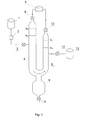
- Fig. 1 presents a system wherein the bioreactor pipes are connected in shape of a letter "U”
- Fig. 2 - a system wherein the bioreactor is shaped in form of a letter "U”, and is provided with one biogas tank and digestate receiver
- Fig. 3 - a system provided with a bioreactor in form of a long pipe and a rock receiver
- Fig. 4 - a system provided with a bioreactor in form of a long pipe and with a waste tank.
- the system (visualised in Fig. 1 ) comprises a substrate tank 1, from which through a metering pump 2 and a non-return valve 3 , the substrate is delivered to the organic matter anaerobic digestion zone, located in the first arm 4 of the bioreactor, shaped in form of a letter "U", whereas in the second arm 5 thereof, of a smaller diameter and height, constituting communicating vessels with the first one, a zone of decreasing hydrostatic pressure is situated.
- the substrate feed pipe is located in the upper part of the first bioreactor arm 4, whereas a computer-controlled gas valve 6 and a biogas tank 7 serve for receiving the biogas, mostly methane containing, produced in a methanisation zone.
- a decreasing hydrostatic pressure zone located in the second arm 5, the carbon dioxide containing traces of methane and produced in the anaerobic digestion process, is removed through a gas valve 10 and received to a biogas tank 11.
- a digestate outlet is located slightly below the substrate inlet level into the bioreactor, and connected through the digestate valve 12 to the digestate tank 13.
- a discharge pipeline 14 and through the valve 15 removed are mineral and non-biodegradable constituents from the chamber 8 for the slow-decomposing sedimenting fraction. Furthermore, a part of separated non-biodegradable solid constituents is periodically removed from the sedimentation zone, while skipping the chamber 8, and is delivered through the valve 16 and the pipeline 17 to the receiver 18, which is a porous rock, accumulating under pressure the waste saturated with carbon dioxide.
- the microbiological decomposition with participation of microorganisms, in spontaneously forming reaction zones proceeds under increasing pressure in a system, wherein the substrate from the tank 1 is metered to the methanogenesis zone situated in the first bioreactor arm 4, through a pump 2, while the valves 6, 9, 10, 12, 15 and 16 remain closed, and the valve 3 is open, until the substrate table level reaches the level h 1 . If at the same time the level h 3 is not reached, opens the valve 10 while the pump 2 remains turned on.
- the pump 2 and the valve 10 to be switched off and the substrate metering to the reactor stops when the substrate table level reaches the value h 3 .
- the liquid phase table levels change, in the first bioreactor arm 4 - between h 1 and h 2 and in the second bioreactor arm 5 between h 4 and h 3 .
- the methane produced as a result of the anaerobic digestion is separated in the upper part of the bioreactor arm 4, and when the level in the upper part of the arm 4 drops at least to h 2 as a result of rising gas pressure, the gas valve 6 opens, releasing the methane flow to the gas tank 7.
- valves 6 and 10 Operation of the valves 6 and 10 is computer-controlled in such a manner that the reference table levels of the liquid phase are changing alternately, and when the substrate table level in the chamber 4 reaches the level h 1 , then the gas valve 6 closes and the gas valve 10 opens.
- the fraction that requires longer digestion time which digestion proceeds then for the extended time in the integrated chamber 8, designed for the slow-decomposing sedimenting fraction, while the mineral and non-biodegradable constituents are periodically, every 30 days, removed through the valve 9 to the receiver 18.
- the receiver 18 is in a form of a porous rock, wherein the digestate saturated with the carbon dioxide and also non-biodegradable wastes are collected under pressure.
- the carbon dioxide produced by the anaerobic digestion and containing traces of methane, is transferred into the biogas tank 11, through the computer-controlled gas valve 10, while the digestate is removed from the bioreactor through the digestate valve 12, into the digestate tank 13.
- the system (visualised in Fig. 2 ), as just as in the embodiment 1, comprises a substrate tank 1, from which through a metering pump 2 and a non-return valve 3, the substrate is delivered to the first arm 4 of the bioreactor shaped in form of a letter "U", whereas the second arm 5 thereof, of a smaller diameter and height, constitutes communicating vessels with the first arm.
- the difference consists in that the produced biogas is removed from the methanogenesis zone 4 through the computer-controlled gas valve 6 into the gas tank 7, into which through the gas valve 10 is also transferred the carbon dioxide containing traces of methane, and coming from the zone of decreasing hydrostatic pressure, located in the second arm 5.
- the mineral and non-biodegradable constituents are removed from the chamber 8, designed for the slow-decomposing sedimenting fraction, through the valve 9 into the receiver, while the digestate saturated with the carbon dioxide is transferred from the zone of decreasing hydrostatic pressure, located in the second arm 5, through the valve 12 into the digestate tank 13.
- the system (visualised in Fig. 3 ), comprises a substrate tank 1, from which through a metering pump 2 and a non-return valve 3, the substrate is delivered to the bioreactor 4 in form of a long pipe.
- the pipeline that delivers the substrate is located in the upper part of the bioreactor, in the zone of organic matter anaerobic digestion.
- the produced separated methane is transferred from the bioreactor through the computer-controlled gas valve 6, into the biogas tank 7.
- the separation zone in the bottom part of the bioreactor 4 is integrated with the chamber 8 for the slow-decomposing sedimenting fraction, wherefrom the mineral and non-biodegradable constituents are removed through the computer-controlled gas valve 9 and by the waste discharge pipeline 17, which is also supplied through the valve 16 with the digestate that has been separated in the separation zone.
- the wastes saturated with carbon dioxide are collected under pressure in the receiver 18, which is a rock workings.
- the sedimentation zone located in the lower part of the bioreactor 4, is connected to the zone of decreasing hydrostatic pressure, located in the ascending vessel 5 .
- the system (visualised in Fig. 4 ), comprises a substrate tank 1, from which through a metering pump 2 and a non-return valve 3, the substrate is delivered to the bioreactor 4 in form of a long pipe.
- the pipeline that delivers the substrate is located in the upper part of the bioreactor, in the zone of organic matter anaerobic digestion.
- the produced separated methane is transferred from the bioreactor through the computer-controlled gas valve 6, into the biogas tank 7.
- the separation zone in the bottom part of the bioreactor 4 is integrated with the chamber 8 for the slow-decomposing sedimenting fraction, wherefrom the mineral and non-biodegradable constituents are removed through the computer-controlled valve 9 and by the digestate discharge pipeline 14, supplied also through the valve 12 with the digestate that has been separated in the separation zone.
- the sedimentation zone located in the lower part of the bioreactor 4, is connected to the ascending vessel 19.
Landscapes
- Health & Medical Sciences (AREA)
- Life Sciences & Earth Sciences (AREA)
- Chemical & Material Sciences (AREA)
- Engineering & Computer Science (AREA)
- Wood Science & Technology (AREA)
- Zoology (AREA)
- Organic Chemistry (AREA)
- Bioinformatics & Cheminformatics (AREA)
- Genetics & Genomics (AREA)
- General Engineering & Computer Science (AREA)
- Sustainable Development (AREA)
- Biochemistry (AREA)
- Microbiology (AREA)
- General Health & Medical Sciences (AREA)
- Biotechnology (AREA)
- Biomedical Technology (AREA)
- Molecular Biology (AREA)
- Analytical Chemistry (AREA)
- Clinical Laboratory Science (AREA)
- General Chemical & Material Sciences (AREA)
- Oil, Petroleum & Natural Gas (AREA)
- Treatment Of Sludge (AREA)
Applications Claiming Priority (2)
| Application Number | Priority Date | Filing Date | Title |
|---|---|---|---|
| PL406704A PL231652B1 (pl) | 2013-12-24 | 2013-12-24 | Sposób wytwarzania metanu i unieszkodliwiania odpadowego dwutlenku węgla oraz urządzenie do stosowania sposobu |
| PL406703A PL231651B1 (pl) | 2013-12-24 | 2013-12-24 | Układ do wytwarzania biogazu z substancji organicznych |
Publications (1)
| Publication Number | Publication Date |
|---|---|
| EP2889364A1 true EP2889364A1 (de) | 2015-07-01 |
Family
ID=52683982
Family Applications (1)
| Application Number | Title | Priority Date | Filing Date |
|---|---|---|---|
| EP14460132.5A Withdrawn EP2889364A1 (de) | 2013-12-24 | 2014-12-23 | Verfahren und vorrichtung zur erzeugung von methan und zur beseitigung von kohlendioxid |
Country Status (1)
| Country | Link |
|---|---|
| EP (1) | EP2889364A1 (de) |
Cited By (2)
| Publication number | Priority date | Publication date | Assignee | Title |
|---|---|---|---|---|
| EP3868859A3 (de) * | 2020-01-28 | 2021-10-27 | SEA S.r.l. | Anlage und verfahren zur herstellung von methan |
| CN115453094A (zh) * | 2022-10-12 | 2022-12-09 | 中国地质调查局油气资源调查中心 | 一种多年冻土冻融区微生物固碳方法 |
Citations (3)
| Publication number | Priority date | Publication date | Assignee | Title |
|---|---|---|---|---|
| US4735724A (en) * | 1986-07-30 | 1988-04-05 | Gas Research Institute | Solids concentrating anaerobic digestion process and apparatus |
| EP0282473A1 (de) * | 1987-03-05 | 1988-09-14 | Funder Industrie Gesellschaft M.B.H. | Verfahren zum kontinuierlichen anaeroben biologischen Abbau von Verbindungen in Abwässern |
| EP1930404A1 (de) * | 2006-12-07 | 2008-06-11 | Organic Waste Systems, Naamloze Vennootschap | Verfahren und Vorrichtung zur anaeroben Fermentation von organischem Material |
-
2014
- 2014-12-23 EP EP14460132.5A patent/EP2889364A1/de not_active Withdrawn
Patent Citations (3)
| Publication number | Priority date | Publication date | Assignee | Title |
|---|---|---|---|---|
| US4735724A (en) * | 1986-07-30 | 1988-04-05 | Gas Research Institute | Solids concentrating anaerobic digestion process and apparatus |
| EP0282473A1 (de) * | 1987-03-05 | 1988-09-14 | Funder Industrie Gesellschaft M.B.H. | Verfahren zum kontinuierlichen anaeroben biologischen Abbau von Verbindungen in Abwässern |
| EP1930404A1 (de) * | 2006-12-07 | 2008-06-11 | Organic Waste Systems, Naamloze Vennootschap | Verfahren und Vorrichtung zur anaeroben Fermentation von organischem Material |
Cited By (2)
| Publication number | Priority date | Publication date | Assignee | Title |
|---|---|---|---|---|
| EP3868859A3 (de) * | 2020-01-28 | 2021-10-27 | SEA S.r.l. | Anlage und verfahren zur herstellung von methan |
| CN115453094A (zh) * | 2022-10-12 | 2022-12-09 | 中国地质调查局油气资源调查中心 | 一种多年冻土冻融区微生物固碳方法 |
Similar Documents
| Publication | Publication Date | Title |
|---|---|---|
| DK2429687T3 (en) | Method and installation for biological treatment of organic waste water | |
| US10179895B2 (en) | Device for fuel and chemical production from biomass-sequestered carbon dioxide and method therefor | |
| Thapa et al. | Enhanced ex-situ biomethanation of hydrogen and carbon dioxide in a trickling filter bed reactor | |
| US20220119289A1 (en) | Process for recovering phosphorus | |
| Meulepas et al. | Biotechnological aspects of sulfate reduction with methane as electron donor | |
| US20130288326A1 (en) | System for anaerobic digestion of solid and soluble organic wastes, by-products and residues | |
| CN109321444B (zh) | 降流式两步厌氧发酵制取氢烷气的方法及生物膜反应器 | |
| CN101811688B (zh) | 采用鸟粪石沉淀法从废水中回收磷的工艺方法 | |
| MD4244C1 (ro) | Reactor anaerob combinat pentru obţinerea biometanului | |
| WO2016027223A1 (en) | Anaerobic membrane bioreactor system | |
| AU2016269738A1 (en) | Method and device for purifying domestic or industrial water | |
| Álvarez et al. | Anaerobic hydrolysis of a municipal wastewater in a pilot-scale digester | |
| CN105417705B (zh) | 一种基于besi技术的压裂返排液生物处理方法 | |
| WO2020124179A1 (pt) | Reator combinado anaeróbio-aeróbio de biofilme fixo para tratamento de águas residuárias | |
| KR100810721B1 (ko) | 매립지 가스 재이용 방법 | |
| CN1938232A (zh) | 用于废水的生物活性污泥处理设备及其操作方法 | |
| JP2008045049A (ja) | ガス成分の簡易分離方法と装置 | |
| JP6538543B2 (ja) | 廃水処理装置、および廃水処理方法 | |
| GB2592841A (en) | Treatment of carbon dioxide containing materials with algae | |
| CN104211173A (zh) | 模块化智能厌氧反应系统 | |
| CN110156154B (zh) | 硫自养反硝化污泥颗粒化及硫泥分离装置及其运行方法 | |
| CN210237236U (zh) | 一种硫自养反硝化污泥颗粒化及硫泥分离装置 | |
| CN202881058U (zh) | 高浓度酒精废水处理系统 | |
| PL231652B1 (pl) | Sposób wytwarzania metanu i unieszkodliwiania odpadowego dwutlenku węgla oraz urządzenie do stosowania sposobu | |
| EP2905328A1 (de) | Verfahren und system zur verarbeitung von organischem material durch anaerobe vergärung |
Legal Events
| Date | Code | Title | Description |
|---|---|---|---|
| PUAI | Public reference made under article 153(3) epc to a published international application that has entered the european phase |
Free format text: ORIGINAL CODE: 0009012 |
|
| 17P | Request for examination filed |
Effective date: 20141223 |
|
| AK | Designated contracting states |
Kind code of ref document: A1 Designated state(s): AL AT BE BG CH CY CZ DE DK EE ES FI FR GB GR HR HU IE IS IT LI LT LU LV MC MK MT NL NO PL PT RO RS SE SI SK SM TR |
|
| AX | Request for extension of the european patent |
Extension state: BA ME |
|
| STAA | Information on the status of an ep patent application or granted ep patent |
Free format text: STATUS: THE APPLICATION IS DEEMED TO BE WITHDRAWN |
|
| 18D | Application deemed to be withdrawn |
Effective date: 20160105 |