EP2889497B1 - Verriegelbares Gelenk für eine zusammenklappbare Vorrichtung zum Befördern von Kindern - Google Patents
Verriegelbares Gelenk für eine zusammenklappbare Vorrichtung zum Befördern von Kindern Download PDFInfo
- Publication number
- EP2889497B1 EP2889497B1 EP14195248.1A EP14195248A EP2889497B1 EP 2889497 B1 EP2889497 B1 EP 2889497B1 EP 14195248 A EP14195248 A EP 14195248A EP 2889497 B1 EP2889497 B1 EP 2889497B1
- Authority
- EP
- European Patent Office
- Prior art keywords
- circular hub
- hinge
- hub element
- leg
- inner non
- Prior art date
- Legal status (The legal status is an assumption and is not a legal conclusion. Google has not performed a legal analysis and makes no representation as to the accuracy of the status listed.)
- Active
Links
Images




Classifications
-
- E—FIXED CONSTRUCTIONS
- E05—LOCKS; KEYS; WINDOW OR DOOR FITTINGS; SAFES
- E05D—HINGES OR SUSPENSION DEVICES FOR DOORS, WINDOWS OR WINGS
- E05D11/00—Additional features or accessories of hinges
- E05D11/10—Devices for preventing movement between relatively-movable hinge parts
- E05D11/1007—Devices for preventing movement between relatively-movable hinge parts with positive locking
-
- B—PERFORMING OPERATIONS; TRANSPORTING
- B62—LAND VEHICLES FOR TRAVELLING OTHERWISE THAN ON RAILS
- B62B—HAND-PROPELLED VEHICLES, e.g. HAND CARTS OR PERAMBULATORS; SLEDGES
- B62B7/00—Carriages for children; Perambulators, e.g. dolls' perambulators
- B62B7/04—Carriages for children; Perambulators, e.g. dolls' perambulators having more than one wheel axis; Steering devices therefor
- B62B7/06—Carriages for children; Perambulators, e.g. dolls' perambulators having more than one wheel axis; Steering devices therefor collapsible or foldable
- B62B7/08—Carriages for children; Perambulators, e.g. dolls' perambulators having more than one wheel axis; Steering devices therefor collapsible or foldable in the direction of, or at right angles to, the wheel axis
-
- E—FIXED CONSTRUCTIONS
- E05—LOCKS; KEYS; WINDOW OR DOOR FITTINGS; SAFES
- E05D—HINGES OR SUSPENSION DEVICES FOR DOORS, WINDOWS OR WINGS
- E05D11/00—Additional features or accessories of hinges
- E05D11/10—Devices for preventing movement between relatively-movable hinge parts
- E05D11/1028—Devices for preventing movement between relatively-movable hinge parts for maintaining the hinge in two or more positions, e.g. intermediate or fully open
-
- F—MECHANICAL ENGINEERING; LIGHTING; HEATING; WEAPONS; BLASTING
- F16—ENGINEERING ELEMENTS AND UNITS; GENERAL MEASURES FOR PRODUCING AND MAINTAINING EFFECTIVE FUNCTIONING OF MACHINES OR INSTALLATIONS; THERMAL INSULATION IN GENERAL
- F16C—SHAFTS; FLEXIBLE SHAFTS; ELEMENTS OR CRANKSHAFT MECHANISMS; ROTARY BODIES OTHER THAN GEARING ELEMENTS; BEARINGS
- F16C11/00—Pivots; Pivotal connections
- F16C11/04—Pivotal connections
- F16C11/045—Pivotal connections with at least a pair of arms pivoting relatively to at least one other arm, all arms being mounted on one pin
-
- F—MECHANICAL ENGINEERING; LIGHTING; HEATING; WEAPONS; BLASTING
- F16—ENGINEERING ELEMENTS AND UNITS; GENERAL MEASURES FOR PRODUCING AND MAINTAINING EFFECTIVE FUNCTIONING OF MACHINES OR INSTALLATIONS; THERMAL INSULATION IN GENERAL
- F16C—SHAFTS; FLEXIBLE SHAFTS; ELEMENTS OR CRANKSHAFT MECHANISMS; ROTARY BODIES OTHER THAN GEARING ELEMENTS; BEARINGS
- F16C11/00—Pivots; Pivotal connections
- F16C11/04—Pivotal connections
- F16C11/10—Arrangements for locking
-
- F—MECHANICAL ENGINEERING; LIGHTING; HEATING; WEAPONS; BLASTING
- F16—ENGINEERING ELEMENTS AND UNITS; GENERAL MEASURES FOR PRODUCING AND MAINTAINING EFFECTIVE FUNCTIONING OF MACHINES OR INSTALLATIONS; THERMAL INSULATION IN GENERAL
- F16C—SHAFTS; FLEXIBLE SHAFTS; ELEMENTS OR CRANKSHAFT MECHANISMS; ROTARY BODIES OTHER THAN GEARING ELEMENTS; BEARINGS
- F16C2326/00—Articles relating to transporting
- F16C2326/20—Land vehicles
Definitions
- aspects and embodiments of the present invention are directed generally to child conveyance devices, for example, strollers and/or car seats, and to hinges on such child conveyance devices.
- GB 2 497 765 A discloses a foldable joint for the frame of a child's stroller comprising a connecting member and a folding member, the connecting member defining at least one receiving slot and the folding member having an end received in the slot.
- EP 1 533 206 A discloses a foldable push chair having two side frames, each side frame having a forward strut means comprising an upper section and a lower section pivotally connected by connection means.
- the connection means allow the upper section and lower section to pivot between a folded state and an unfolded state.
- the hinge includes an outer non-circular hub element comprising a first side and second side, wherein the first side and second side define a groove.
- An inner non-circular hub element is coupled to the outer non-circular hub element and configured to fit at least partially within the groove of the outer non-circular hub element.
- a width of the groove is less than about 9 millimeters.
- the width of the groove is between about 5 and about 9 millimeters.
- the outer non-circular hub element is coupled to the inner non-circular hub element at a point off-centered from a center line or centroid of the outer non-circular hub element.
- the hinge further comprises a first leg coupled to the outer non-circular hub element, a second leg coupled to the inner non-circular hub element, and a locking mechanism including a carriage biased toward the inner non-circular hub element and configured to engage a notch in the inner non-circular hub element, engagement of the carriage with the notch locking the first leg and the second leg in a position relative to one another.
- the carriage and a mechanism for biasing the carriage toward the inner non-circular hub element may be disposed in the first leg.
- Some aspects are directed toward a child conveyance device including a frame assembly including the hinge.
- Some aspects are directed toward a hinge including an outer non-circular hub element and an inner non-circular hub element coupled to the outer non-circular hub element and configured to rotate within the outer non-circular hub element, the inner non-circular hub element including a rounded edge defined by a surface between a planar surface of the inner non-circular hub element and a rim surface of the inner non-circular element.
- the inner non-circular hub element comprises a notch configured to engage with a carriage to lock the hinge.
- the notch comprises one or more surfaces angled and angles greater than about 90 degrees relative to an adjacent surface of the notch.
- the notch may include a first side wall sloped at an angle greater than about 90 degrees relative to an adjacent second side wall of the notch.
- the carriage may include ramped external surfaces configured to engage the first side wall of the notch and the second side wall of the notch when the hinge is in a locked position.
- This disclosure is directed toward a hinge including an outer non-circular hub element including a groove and an inner non-circular hub element coupled to the outer non-circular hub element and configured to rotate within the groove of the outer non-circular hub element, wherein a surface of the inner non-circular hub element is sloped at an angle greater than about 90 degrees relative to a planar surface of the inner non-circular hub element.
- the surface is sloped at an angle of greater than about 110 degrees relative to the planar surface of the inner non-circular hub element.
- a second surface of the outer non-circular hub element is sloped at an angle greater than about 90 degrees relative to a planar surface of the outer non-circular hub element.
- the second surface is sloped at an angle of greater than about 110 degrees relative to the planar surface of the outer non-circular hub element.
- the hinge further includes a first inset element disposed between a first surface of the inner non-circular hub element and a first surface of the outer non-circular hub element.
- the hinge further includes a second inset element disposed between a second surface of the inner non-circular hub element and a second surface of the outer non-circular hub element.
- the first and second inset elements each include a plate made of a low-friction material.
- the first and second inset elements each comprise a pad made of a low-friction material.
- This invention is directed toward a hinge for a child conveyance device including a means for coupling two non-circular elements that rotate with respect to one another, wherein the two non-circular elements are configured to avoid the pinching of fingers during rotation.
- This invention is directed toward a hinge for a child conveyance device including an outer non-circular hub element comprising a first side and second side, wherein in the first side and second side define a groove, an inner non-circular hub element configured to fit at least partially within the groove of the outer non-circular hub element, and a means for coupling the outer non-circular hub element and the inner non-circular hub element.
- Parents or caregivers of young children or babies may transport a child in child conveyance devices, such as car seats and strollers. Such devices are more convenient to transport or store if the devices can collapse or otherwise be configured to take up less space when the child is not in the device.
- the devices can be configured to collapse by coupling components of a frame of the devices with hinges, in a manner which would allow the frame to fold.
- a hinge can result in pinching of fingers or skin within the hinge.
- Such pinching can be particularly problematic on a child conveyance device, as children and babies' fingers can be smaller and more delicate, thus more susceptible to pinching and with greater consequence.
- a hinge for use on child conveyance devices.
- the term "child conveyance device” includes any apparatus, mobile or stationary, in which a child may be placed wherein it may be desirable to include elements that fold or move by coupling with a hinge.
- a child conveyance device may be any of a stroller, a car seat, or a child swing.
- a hinge 100 includes a first leg 102 and a second leg 106.
- the first leg 102 and the second leg 106 are coupled at a pivot point 110.
- the first leg 102 includes an outer hub 104.
- the second leg 106 includes a relatively planar surface forming an inner hub 108.
- the inner hub 108 of the second leg 106 is designed to fit in the outer hub 104 of the first leg 102 so that the inner hub 108 can rotate within the outer hub 104 about the pivot point 110.
- the pivot point 110 may be off centered from a centroid or center line of the outer hub 104 and/or inner hub 108.
- the first leg 102 and second leg 106 may be coupled to additional components to constitute a frame assembly or a portion of a frame assembly for a child conveyance device.
- the inner hub 108 and/or the outer hub 104 are non-circular elements which may be partially circular or curved in shape. In some embodiments, the inner hub 108 and/or the outer hub 104 do not include curved portions.
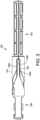
- the hinge 100 is designed to lock into a position when the hinge 100 is extended. Locking of the hinge 100 may include releasably retaining the first leg 102 and the second leg 106 at a fixed angle or position relative to one another or releasably securing the first leg 102 to the second leg 106 at a fixed angle or position relative to one another. The locking mechanism is described further below with reference to FIGS. 6 and 7 . In some embodiments, the hinge 100 may lock when the hinge is in a fully extended position, such as when the first leg 102 and the second leg 106 are substantially aligned at a 180-degree angle.
- the hinge 100 may lock when the hinge 100 is not fully extended or when the first leg 102 and second leg 106 are approximately parallel. In various embodiments, the hinge 100 may lock with the first leg 102 and the second leg 106 disposed at any angle between 0 degrees and 180 degrees relative to each other, for example, at angles of 45 degrees, 90 degrees, or 135 degrees relative to each other. Embodiments disclosed herein are not limited to any particular angle between the first leg 102 and the second leg 106 at which the hinge may lock.
- an angle between the first leg 102 and the second leg 106 at which the hinge may lock may be adjustable and/or the hinge may be configured to lock at with the first leg 102 and the second leg 106 disposed at any of a plurality of different angles relative to one another.
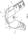
- FIG. 4 shows the hinge 100 in a flexed position.
- the non-hub portions of the first leg 102 and the second leg 106 may have an elliptical cross-sections.
- the non-hub portions of the first leg 102 and/or the second leg 106 may have circular cross-sections, rectangular cross-sections, or cross-sections of any desired geometric shape.
- The-cross sections of the non-hub portions of the first leg 102 and/or the second leg 106 may change in shape or size along the length of the first leg 102 and/or the second leg 106.
- the cross-section of at least a portion of the non-hub portion of the first leg 102 may differ from the cross-section of at least a portion of the non-hub portion of the second leg 106.
- the second leg 106 tapers so that the inner hub 108 is flatter than the remainder of the second leg 106 so that the inner hub 108 can fit into a groove 113 of the outer hub 104.
- a tapered section 116 of the second leg 106 is configured to direct fingers and other flesh away from the hubs 104, 108 as the hubs 104, 108 rotate.
- the tapered section 116 is be disposed between and couple the inner hub 108 to the non-hub portion of the second leg 106.
- the tapered section 116 may be chamfered or sloped on one or both of a first and a second surface so that when the inner hub 108 rotates into the outer hub 104, fingers will slide up the slope of the tapered section 116 away from the rotating hubs 104, 108, rather than getting caught in between the hubs 104, 108 and the remainder of the second leg 106.
- one or both of the first and second surfaces of the tapered section 116 is sloped at an obtuse angle of greater than about 90 degrees, greater than about 100 degrees, greater than about 110 degrees, or greater than about 120 degrees relative to a flat surface of the inner hub 108 and/or relative to a flat outer surface of the outer hub 104.
- the tapered section 116 includes curved first and the second surfaces.
- the first and second surfaces may taper at the same or different angles relative to a planar surface of the inner hub 108 or may curve in a similar or different manner relative to a planar surface of the inner hub 108.
- the outer hub 104 has a corresponding outer tapered section 114, which may be designed to direct fingers away from the rotating hubs 104, 108.
- the tapered section 114 may include surfaces which are chamfered, sloped, or curved relative to a planar surface of the outer hub 104 in a similar manner as the tapered section 116 of the second leg 106 is chamfered, sloped, or curved relative to a planar surface of the inner hub 108.
- the tapered section 114 of the first leg 102 will force fingers and other flesh to slide away from an interface between the hubs 104, 108 upon the closing of the hubs 104, 108 as the inner hub 108 rotates into the outer hub 104.
- the degree of slope, curvature, and the/or the shapes of the tapered sections 114, 116 of the outer hub 104 and of the second leg 106, respectively, may be substantially the same or may be different.
- the groove 113 of the outer hub 104 is configured to prevent pinching of fingers and flesh.
- the groove 113 of the outer hub 108 may have a width which is small enough so that fingers of a child and/or an adult would not be able to fit into the groove 113.
- the width of the groove 113 may be less than about 9 mm, between about 9 mm and about 5 mm, or about 5 mm or less.
- the width of the inner hub 108 may be correspondingly sized to fit into a smaller-width groove.
- the inner hub 108 is configured to prevent scissoring, which can pinch fingers and flesh.
- the edges of the inner hub 108 may be configured to be blunted or rounded and not sharp.
- At least one edge of the inner hub 108 may be shaped or may include an additional surface 118 such that a planar surface 108a of the inner hub 108 and a rim 108b of the inner hub 108 do not meet at a perpendicular angle.
- the additional surface 118 may provide an extra step between the planar surface 108a and rim surface 108b, allowing for a larger angle at an adjoining border between the planar surface 108a and rim surface 108b of the inner hub 108.
- the inner hub 108 may also include a notch 112, which may be a part of a locking mechanism for the hinge, described further below.
- the notch 112 may be configured to prevent pinching and scissoring of flesh.
- the notch 112 may be sloped with obtuse angles that displace fingers or other body parts placed in the notch 112 in a direction outward from the outer hub 104 as the inner hub 108 rotates into the outer hub 104.
- the notch 112 may include a first side wall sloped at an obtuse angle greater than about 90 degrees relative to an adjacent second side wall of the notch in a plane defined by a planar surface of the inner hub.
- obtuse angle of the notch 112 directs away from the outer hub 104, as the hubs 104, 108 rotate a finger or other flesh present in the notch 112 would be directed out of the notch 112 instead of into a position pinched between the two hubs 104, 108.
- Other appropriate edges and components of the hubs 104, 108 and the first and second legs 102, 106 may be similarly configured to prevent pinching.
- other components can also be sloped, use obtuse angles, and/or be configured to eliminate sharp edges.
- the hinge 100 may be configured to lock in a certain position.
- the hinge 100 locks when the first leg 102 and the second leg 106 are positioned substantially at a 180-degree angle relative to one another.
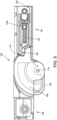
- the hinge 100 is locked into place by a carriage 120 in the first leg 102 which is pushed into the notch 112 of the inner hub 108 when the notch 112 is aligned with the carriage 120, for example, by rotating the first leg 102 and second leg 106 into positions at a substantially 180-degree angle relative to one another.
- the carriage 120 may be pushed into the notch 112 by a spring 122 to lock the hinge 100 into place.
- the spring 122 may be disposed within the first leg 102 and may be attached to a spring retainer 122a.
- the spring 122 may exert a force on the carriage 120 which pushes the carriage 120 away from the spring retainer 122a and toward the inner hub 108.
- the carriage 120 may be shaped so that the rotation of the inner hub 108 forces the carriage 120 against the spring until the notch 112 of the inner hub 108 rotates past the carriage 120. Additionally, the carriage 120 may include a ramped end surface 124 designed to engage a ramped surface of the notch 112. The ramped surfaces of the carriage 120 and complementary ramped internal surfaces of the notch 112 may provide for a more obtuse angle of the notch 112 to prevent pinching, and also may provide for the carriage 120 to wedge into the notch to minimize rotational play in the hinge 100 when the hinge 100 is in a locked position.
- the carriage 120 may be released from the notch 112 using a pull cable 126, a switch, a lever, or other appropriate mechanism to allow the hinge to unlock and flex. While the hinge 100 of FIGS. 5 and 6 show the locked position to be one where the first leg 102 and second leg 106 are disposed in positions substantially 180 degrees apart, the hinge 100 may also or alternatively be locked in other positions. In some embodiments, the hinge 100 may have multiple locking positions. For example, the inner hub 108 may have more than one notch 112 at different locations on the inner hub 108 configured to engage the carriage 120.
- FIG. 7 shows an exploded view of an embodiment of a hinge 200.
- the hinge 200 may include similar components as those described above, such as a first leg 202a, 202b with an outer hub and a second leg 206 with an inner hub 208.
- the first leg may be made of two pieces 202a, 202b, which are coupled together around a portion of the second leg 206 and/or the inner hub 208.
- the hinge 200 may also include inset plates 230, 232.
- the inset plates 230, 232 may be made of or coated with a low-friction polymer such as polyoxymethylene (POM) or polytetrafluoroethylene (PTFE).
- POM polyoxymethylene
- PTFE polytetrafluoroethylene
- the inset plates 230, 232 may be positioned between the inner hub 208 and the two sections of the outer hub 204a, 204b.
- the inset plates 230, 232 may minimize sliding friction between the plates of the inner hub 208 and outer hub to reduce wear on the hinge 200.
- the inner hub 208 and outer hub of the hinge 200 may be made of metal.
- the inner and/or outer hubs may be forged or die-cast out of aluminum, magnesium zinc, or titanium.
- the inner and/or outer hubs may be formed of a plastic material, for example, polyethylene or polypropylene.
- Embodiments of the hinge are not limited to any particular material of construction of the inner and/or outer hubs or of other components of the hinge.
- FIG. 8 shows an embodiment of hinge 300 with an inset pad 330 present between a surface of the inner hub 308 and the side piece 302a of the first leg of the hinge 300.
- the inset pad 330 may be fixed in place on the inner hub 308 by a protrusion 330a disposed in an aperture 308a in the inner hub 308.
- An additional inset pad may be present between the opposite surface of the inner hub 308 and a second side piece of the first leg of the hinge 300.
- the second side piece of the first leg of the hinge 300 has been omitted from FIG. 8 to illustrate the internal features of the hinge 300.
- the inset pad 330 and the additional inset pad present between the inner hub 308 and the second side piece of the first leg of the hinge 300 may serve a similar function as the inset plates 230, 232 of the hinge 200 of FIG. 7 .
- the inset pads 330, 332 may be made of or coated with a low-friction polymer to minimize sliding friction between the metal plates of an inner hub 308 and an outer hub 304.
- the inset pads may be positioned on the inner hub 308, the outer hub 304, or trapped in between the hubs 304, 308. In some embodiments, one or more inset pads may be positioned around a pivot point 310.
Landscapes
- Engineering & Computer Science (AREA)
- Mechanical Engineering (AREA)
- General Engineering & Computer Science (AREA)
- Chemical & Material Sciences (AREA)
- Combustion & Propulsion (AREA)
- Transportation (AREA)
- Pivots And Pivotal Connections (AREA)
- Carriages For Children, Sleds, And Other Hand-Operated Vehicles (AREA)
Claims (13)
- Scharnier für eine Vorrichtung zum Befördern eines Kindes, wobei das Scharnier Folgendes umfasst:einen ersten Schenkel (102), der mit einem äußeren nicht kreisförmigen Zentralelement (104) verbunden ist, das eine erste Seite (204a) und eine zweite Seite (204b) enthält, wobei die erste Seite und die zweite Seite eine Nut (113) definieren,ein inneres nicht kreisförmiges Zentralelement (108), das mit dem äußeren nicht kreisförmigen Zentralelement (104) verbunden ist und dazu konfiguriert ist, mindestens teilweise in die Nut des äußeren nicht kreisförmigen Zentralelements zu passen; undeinen zweiten Schenkel (106), der einen verjüngten Bereich (116) enthält, der das innere nicht kreisförmige Zentralelement mit einem Nicht-Zentralabschnitt des zweiten Schenkels verbindet, wobei der verjüngte Bereich (116) eine erste Oberfläche enthält, die in einem stumpfen Winkel relativ zu einer flachen Oberfläche des inneren nicht kreisförmigen Zentralelements (108) geneigt und relativ zu der flachen Oberfläche des inneren nicht kreisförmigen Zentralelements (108) gekrümmt ist, wobei der verjüngte Bereich (116) eine zweite Oberfläche enthält, die in einem stumpfen Winkel relativ zu der flachen Oberfläche des inneren nicht kreisförmigen Zentralelements (108) geneigt und relativ zu der flachen Oberfläche des inneren nicht kreisförmigen Zentralelements (108) gekrümmt ist, wobei das äußere nicht kreisförmige Zentralelement (104) einen äußeren verjüngten Bereich (114) enthält, der eine erste und eine zweite Oberfläche enthält, wobei jede davon in einem stumpfen Winkel relativ zu einer ebenen Oberfläche des äußeren nicht kreisförmigen Zentralelements (104) geneigt ist, sodass der verjüngte Bereich und der äußere verjüngte Bereich dazu konfiguriert sind, zu bewirken, dass die Finger eines Benutzers an dem jeweiligen verjüngten Bereich und äußeren verjüngten Bereich in eine Richtung weg von den rotierenden Zentralelementen (104, 108) und der Schnittstelle zwischen den Zentren nach oben gleiten, wenn das innere nicht kreisförmige Zentralelement sich in das äußere nicht kreisförmige Zentralelement dreht.
- Scharnier nach Anspruch 1, wobei das äußere nicht kreisförmige Zentralelement (104) mit dem inneren nicht kreisförmigen Zentralelement (108) an einem Punkt (110) verbunden ist, der außermittig von einem Schwerpunkt des äußeren nicht kreisförmigen Zentralelements (104) liegt.
- Scharnier nach Anspruch 1 oder Anspruch 2, ferner einen Verriegelungsmechanismus umfassend, der einen Schlitten (120) enthält, der zu dem inneren nicht kreisförmigen Zentralelement hin vorgespannt ist und dazu konfiguriert ist, eine Kerbe (112) in dem inneren nicht kreisförmigen Zentralelement in Eingriff zu nehmen, wobei das Eingreifen des Schlittens in die Kerbe den ersten Schenkel und den zweiten Schenkel in einer Position relativ zueinander verriegelt.
- Scharnier nach Anspruch 3, wobei der Schlitten und ein Mechanismus (122, 122a) zum Vorspannen des Schlittens zu dem inneren nicht kreisförmigen Zentralelement hin in dem ersten Schenkel angeordnet sind.
- Scharnier nach Anspruch 3 oder Anspruch 4, wobei die Kerbe eine erste Seitenwand enthält, die in einem Winkel von mehr als 90 Grad relativ zu einer benachbarten zweiten Seitenwand der Kerbe in einer Ebene geneigt ist, die durch eine ebene Oberfläche des inneren nicht kreisförmigen Zentralelements definiert ist.
- Scharnier nach Anspruch 5, wobei der Schlitten schräge äußere Oberflächen (124) enthält, die dazu konfiguriert sind, mit der ersten Seitenwand der Kerbe und der zweiten Seitenwand der Kerbe in Eingriff zu gelangen, wenn sich das Scharnier in einer verriegelten Position befindet.
- Scharnier nach einem vorhergehenden Anspruch, wobei das innere nicht kreisförmige Zentralelement eine abgerundete Kante enthält, die durch eine Oberfläche (118) zwischen einer ebenen Oberfläche (108a) des inneren nicht kreisförmigen Zentralelements und einer Randoberfläche (108b) des inneren nicht kreisförmigen Elements definiert ist, sodass die ebene Oberfläche des inneren nicht kreisförmigen Zentralelements und die Randoberfläche des inneren nicht kreisförmigen Zentralelements nicht in einem rechten Winkel zusammentreffen.
- Scharnier nach einem vorhergehenden Anspruch, wobei der verjüngte Bereich in einem Winkel von mehr als 110 Grad relativ zu der flachen Oberfläche des inneren nicht kreisförmigen Zentralelements geneigt ist.
- Scharnier nach einem vorhergehenden Anspruch, ferner ein erstes Einsatzelement (230) umfassend, das zwischen einer ersten Oberfläche des inneren nicht kreisförmigen Zentralelements und einer ersten Oberfläche des äußeren nicht kreisförmigen Zentralelements angeordnet ist.
- Scharnier nach Anspruch 9, ferner ein zweites Einsatzelement (232) umfassend, das zwischen einer zweiten Oberfläche des inneren nicht kreisförmigen Zentralelements und einer zweiten Oberfläche des äußeren nicht kreisförmigen Zentralelements angeordnet ist.
- Scharnier nach Anspruch 10, wobei das erste und das zweite Einsatzelement jeweils ein reibungsarmes Material enthalten.
- Scharnier nach Anspruch 10, wobei das erste und das zweite Einsatzelement jeweils ein Polster (330) aus einem reibungsarmen Material umfassen.
- Vorrichtung zum Befördern eines Kindes, eine Rahmenanordnung umfassend, die das Scharnier nach einem vorhergehenden Anspruch enthält.
Applications Claiming Priority (1)
| Application Number | Priority Date | Filing Date | Title |
|---|---|---|---|
| US14/098,209 US10145159B2 (en) | 2013-12-05 | 2013-12-05 | Collapsible child conveyance device |
Publications (2)
| Publication Number | Publication Date |
|---|---|
| EP2889497A1 EP2889497A1 (de) | 2015-07-01 |
| EP2889497B1 true EP2889497B1 (de) | 2025-01-01 |
Family
ID=52102412
Family Applications (1)
| Application Number | Title | Priority Date | Filing Date |
|---|---|---|---|
| EP14195248.1A Active EP2889497B1 (de) | 2013-12-05 | 2014-11-27 | Verriegelbares Gelenk für eine zusammenklappbare Vorrichtung zum Befördern von Kindern |
Country Status (3)
| Country | Link |
|---|---|
| US (1) | US10145159B2 (de) |
| EP (1) | EP2889497B1 (de) |
| CN (1) | CN104691599A (de) |
Families Citing this family (6)
| Publication number | Priority date | Publication date | Assignee | Title |
|---|---|---|---|---|
| US9938746B2 (en) * | 2015-07-06 | 2018-04-10 | Timothy Parsons | Snap-locking hinge joint |
| US9908551B2 (en) | 2015-09-02 | 2018-03-06 | Artsana USA, Inc | Travel stroller folding and latch mechanism |
| GB2545783B (en) * | 2015-11-23 | 2019-04-10 | Wonderland Switzerland Ag | Infant stroller apparatus |
| CN107284506B (zh) * | 2016-04-13 | 2019-11-19 | 明门香港股份有限公司 | 折叠座椅组及婴儿车 |
| US10449987B2 (en) | 2018-01-17 | 2019-10-22 | Evenflo Company, Inc. | Tandem stroller with sliding carriage |
| EP4308775A4 (de) * | 2021-03-16 | 2025-03-19 | Leisurelife (Aust) Pty Ltd | Scharniergelenk und verfahren zur verwendung |
Family Cites Families (18)
| Publication number | Priority date | Publication date | Assignee | Title |
|---|---|---|---|---|
| US659878A (en) * | 1900-08-15 | 1900-10-16 | Gorham Mfg Company | Portmanteau-frame. |
| US784574A (en) * | 1904-06-07 | 1905-03-14 | Charles N Langdon | Pivoting device for ventilating-sashes. |
| DE2514940C2 (de) * | 1975-04-05 | 1985-03-07 | Wilhelm Bahmüller Maschinen- und Apparatebau, 7067 Plüderhausen | In mehreren Arbeitsstellungen verriegelbares Gelenk zur Verbindung der Leiterholme einer in mehreren Stellungen verrastbaren Leiter oder dergl. |
| US4286353A (en) * | 1978-12-11 | 1981-09-01 | R. D. Werner Co., Inc. | Multi-element connection for structural members |
| US5054165A (en) * | 1989-11-06 | 1991-10-08 | Atwood Industries, Inc. | Door on-door off vehicle hinge with hold-open mechanism |
| US5142739A (en) * | 1991-07-02 | 1992-09-01 | Palhood Industries Corporation | Lockable hinge joint for folding ladders |
| US5251359A (en) * | 1992-06-22 | 1993-10-12 | Finkl Anthony W | Heavy duty offset tube hinge |
| US6711780B2 (en) | 2001-08-22 | 2004-03-30 | Sinclair Worldwide, Inc. | Hinge for collapsible ladders |
| WO2005031104A1 (en) * | 2003-09-22 | 2005-04-07 | Werner Co. | Dynamic hinge for ladder |
| GB2408240B (en) | 2003-11-21 | 2007-05-23 | Armon Ltd | Folding push chair |
| KR200349726Y1 (ko) * | 2004-01-29 | 2004-05-12 | 주식회사 봉천 | 접철식 사다리용 힌지장치에 사용되는 안전부재 |
| US20070101493A1 (en) * | 2005-11-05 | 2007-05-10 | Campbell David E | Collapsible crib |
| US8408225B2 (en) | 2009-11-12 | 2013-04-02 | Go Papa, Lllc | Collapsible shelter |
| CN102101490B (zh) | 2009-12-18 | 2014-07-16 | 明门香港股份有限公司 | 可收合式婴幼儿承载装置 |
| GB2483307A (en) | 2010-09-06 | 2012-03-07 | Mamas & Papas Ltd | A hinge adapted for an infant support apparatus designed to prevent finger trapping |
| US20140037365A1 (en) | 2011-04-07 | 2014-02-06 | Funtastic Limited | Finger guard |
| GB2497764A (en) | 2011-12-19 | 2013-06-26 | Teng Mei Sheng | An anti-pinch folding joint for a stroller |
| GB2497765A (en) | 2011-12-19 | 2013-06-26 | Teng Mei Sheng | An anti-pinch folding and locking joint for a stroller |
-
2013
- 2013-12-05 US US14/098,209 patent/US10145159B2/en active Active
-
2014
- 2014-11-27 EP EP14195248.1A patent/EP2889497B1/de active Active
- 2014-11-28 CN CN201410708502.XA patent/CN104691599A/zh active Pending
Also Published As
| Publication number | Publication date |
|---|---|
| US10145159B2 (en) | 2018-12-04 |
| US20150159414A1 (en) | 2015-06-11 |
| CN104691599A (zh) | 2015-06-10 |
| EP2889497A1 (de) | 2015-07-01 |
Similar Documents
| Publication | Publication Date | Title |
|---|---|---|
| EP2889497A1 (de) | Verriegelbares Gelenk für eine zusammenklappbare Vorrichtung zum Befördern von Kindern | |
| US8961057B2 (en) | Fold latch and fold joint for a stroller | |
| CN103381847B (zh) | 用于使儿童就坐的装置及其铰接组件 | |
| EP3263420B1 (de) | Kinderwagenvorrichtung | |
| CN204137084U (zh) | 用于推车的铰链和可折叠推车 | |
| US4856809A (en) | Collapsible stroller with stowable tray | |
| US8622404B2 (en) | Infant carrier apparatus and its adjusting method | |
| CN102384153B (zh) | 婴幼儿支撑器械 | |
| US8205943B2 (en) | Foldable rocking chair | |
| EP2990298B1 (de) | Spielfreies scharnier für einen kinderwagen | |
| EP3272621B1 (de) | Zusammenklappbarer kinderwagenrahmen | |
| US20140334867A1 (en) | Pivot joint for a stroller frame | |
| JP2009012579A (ja) | 乳母車 | |
| CN103359148A (zh) | 婴儿车 | |
| US20110181026A1 (en) | Joint assembly with safety locking mechanisms for baby stroller | |
| TWI853685B (zh) | 嬰幼兒載具 | |
| US8353520B2 (en) | Infant carrier apparatus with a joint structure having an anti-pinch safety feature | |
| US10973307B1 (en) | Foldable frame for hammock swing | |
| CN109475455B (zh) | 可折叠移动辅助设备 | |
| TWI858343B (zh) | 安全座椅 | |
| KR102176728B1 (ko) | 폴딩형 유모차 | |
| EP4408721B1 (de) | Kinderwagen | |
| CN222793590U (zh) | 一种收合机构及儿童推车 | |
| CN117401017A (zh) | 可收合载具及儿童承载装置 | |
| JP2010254005A (ja) | 折畳み式ベビーカーのロック解除装置、該ロック解除装置を備えた折畳み式ベビーカー |
Legal Events
| Date | Code | Title | Description |
|---|---|---|---|
| PUAI | Public reference made under article 153(3) epc to a published international application that has entered the european phase |
Free format text: ORIGINAL CODE: 0009012 |
|
| 17P | Request for examination filed |
Effective date: 20141127 |
|
| AK | Designated contracting states |
Kind code of ref document: A1 Designated state(s): AL AT BE BG CH CY CZ DE DK EE ES FI FR GB GR HR HU IE IS IT LI LT LU LV MC MK MT NL NO PL PT RO RS SE SI SK SM TR |
|
| AX | Request for extension of the european patent |
Extension state: BA ME |
|
| R17P | Request for examination filed (corrected) |
Effective date: 20151222 |
|
| RBV | Designated contracting states (corrected) |
Designated state(s): AL AT BE BG CH CY CZ DE DK EE ES FI FR GB GR HR HU IE IS IT LI LT LU LV MC MK MT NL NO PL PT RO RS SE SI SK SM TR |
|
| STAA | Information on the status of an ep patent application or granted ep patent |
Free format text: STATUS: EXAMINATION IS IN PROGRESS |
|
| 17Q | First examination report despatched |
Effective date: 20200602 |
|
| GRAP | Despatch of communication of intention to grant a patent |
Free format text: ORIGINAL CODE: EPIDOSNIGR1 |
|
| STAA | Information on the status of an ep patent application or granted ep patent |
Free format text: STATUS: GRANT OF PATENT IS INTENDED |
|
| RIC1 | Information provided on ipc code assigned before grant |
Ipc: B62B 7/08 20060101ALI20240610BHEP Ipc: F16C 11/04 20060101ALI20240610BHEP Ipc: F16C 11/10 20060101AFI20240610BHEP |
|
| INTG | Intention to grant announced |
Effective date: 20240715 |
|
| GRAS | Grant fee paid |
Free format text: ORIGINAL CODE: EPIDOSNIGR3 |
|
| GRAA | (expected) grant |
Free format text: ORIGINAL CODE: 0009210 |
|
| STAA | Information on the status of an ep patent application or granted ep patent |
Free format text: STATUS: THE PATENT HAS BEEN GRANTED |
|
| AK | Designated contracting states |
Kind code of ref document: B1 Designated state(s): AL AT BE BG CH CY CZ DE DK EE ES FI FR GB GR HR HU IE IS IT LI LT LU LV MC MK MT NL NO PL PT RO RS SE SI SK SM TR |
|
| REG | Reference to a national code |
Ref country code: GB Ref legal event code: FG4D |
|
| REG | Reference to a national code |
Ref country code: CH Ref legal event code: EP |
|
| REG | Reference to a national code |
Ref country code: DE Ref legal event code: R096 Ref document number: 602014091397 Country of ref document: DE |
|
| REG | Reference to a national code |
Ref country code: IE Ref legal event code: FG4D |
|
| REG | Reference to a national code |
Ref country code: LT Ref legal event code: MG9D |
|
| REG | Reference to a national code |
Ref country code: NL Ref legal event code: MP Effective date: 20250101 |
|
| REG | Reference to a national code |
Ref country code: AT Ref legal event code: MK05 Ref document number: 1756529 Country of ref document: AT Kind code of ref document: T Effective date: 20250101 |
|
| PG25 | Lapsed in a contracting state [announced via postgrant information from national office to epo] |
Ref country code: NL Free format text: LAPSE BECAUSE OF FAILURE TO SUBMIT A TRANSLATION OF THE DESCRIPTION OR TO PAY THE FEE WITHIN THE PRESCRIBED TIME-LIMIT Effective date: 20250101 |
|
| PG25 | Lapsed in a contracting state [announced via postgrant information from national office to epo] |
Ref country code: FI Free format text: LAPSE BECAUSE OF FAILURE TO SUBMIT A TRANSLATION OF THE DESCRIPTION OR TO PAY THE FEE WITHIN THE PRESCRIBED TIME-LIMIT Effective date: 20250101 |
|
| PG25 | Lapsed in a contracting state [announced via postgrant information from national office to epo] |
Ref country code: PL Free format text: LAPSE BECAUSE OF FAILURE TO SUBMIT A TRANSLATION OF THE DESCRIPTION OR TO PAY THE FEE WITHIN THE PRESCRIBED TIME-LIMIT Effective date: 20250101 |
|
| PG25 | Lapsed in a contracting state [announced via postgrant information from national office to epo] |
Ref country code: ES Free format text: LAPSE BECAUSE OF FAILURE TO SUBMIT A TRANSLATION OF THE DESCRIPTION OR TO PAY THE FEE WITHIN THE PRESCRIBED TIME-LIMIT Effective date: 20250101 |
|
| PG25 | Lapsed in a contracting state [announced via postgrant information from national office to epo] |
Ref country code: NO Free format text: LAPSE BECAUSE OF FAILURE TO SUBMIT A TRANSLATION OF THE DESCRIPTION OR TO PAY THE FEE WITHIN THE PRESCRIBED TIME-LIMIT Effective date: 20250401 Ref country code: IS Free format text: LAPSE BECAUSE OF FAILURE TO SUBMIT A TRANSLATION OF THE DESCRIPTION OR TO PAY THE FEE WITHIN THE PRESCRIBED TIME-LIMIT Effective date: 20250501 |
|
| PG25 | Lapsed in a contracting state [announced via postgrant information from national office to epo] |
Ref country code: HR Free format text: LAPSE BECAUSE OF FAILURE TO SUBMIT A TRANSLATION OF THE DESCRIPTION OR TO PAY THE FEE WITHIN THE PRESCRIBED TIME-LIMIT Effective date: 20250101 |
|
| PG25 | Lapsed in a contracting state [announced via postgrant information from national office to epo] |
Ref country code: LV Free format text: LAPSE BECAUSE OF FAILURE TO SUBMIT A TRANSLATION OF THE DESCRIPTION OR TO PAY THE FEE WITHIN THE PRESCRIBED TIME-LIMIT Effective date: 20250101 Ref country code: PT Free format text: LAPSE BECAUSE OF FAILURE TO SUBMIT A TRANSLATION OF THE DESCRIPTION OR TO PAY THE FEE WITHIN THE PRESCRIBED TIME-LIMIT Effective date: 20250502 |
|
| PG25 | Lapsed in a contracting state [announced via postgrant information from national office to epo] |
Ref country code: GR Free format text: LAPSE BECAUSE OF FAILURE TO SUBMIT A TRANSLATION OF THE DESCRIPTION OR TO PAY THE FEE WITHIN THE PRESCRIBED TIME-LIMIT Effective date: 20250402 Ref country code: BG Free format text: LAPSE BECAUSE OF FAILURE TO SUBMIT A TRANSLATION OF THE DESCRIPTION OR TO PAY THE FEE WITHIN THE PRESCRIBED TIME-LIMIT Effective date: 20250101 |
|
| PG25 | Lapsed in a contracting state [announced via postgrant information from national office to epo] |
Ref country code: AT Free format text: LAPSE BECAUSE OF FAILURE TO SUBMIT A TRANSLATION OF THE DESCRIPTION OR TO PAY THE FEE WITHIN THE PRESCRIBED TIME-LIMIT Effective date: 20250101 |
|
| PG25 | Lapsed in a contracting state [announced via postgrant information from national office to epo] |
Ref country code: CZ Free format text: LAPSE BECAUSE OF FAILURE TO SUBMIT A TRANSLATION OF THE DESCRIPTION OR TO PAY THE FEE WITHIN THE PRESCRIBED TIME-LIMIT Effective date: 20250101 |
|
| PG25 | Lapsed in a contracting state [announced via postgrant information from national office to epo] |
Ref country code: SE Free format text: LAPSE BECAUSE OF FAILURE TO SUBMIT A TRANSLATION OF THE DESCRIPTION OR TO PAY THE FEE WITHIN THE PRESCRIBED TIME-LIMIT Effective date: 20250101 |
|
| REG | Reference to a national code |
Ref country code: DE Ref legal event code: R097 Ref document number: 602014091397 Country of ref document: DE |
|
| PG25 | Lapsed in a contracting state [announced via postgrant information from national office to epo] |
Ref country code: SM Free format text: LAPSE BECAUSE OF FAILURE TO SUBMIT A TRANSLATION OF THE DESCRIPTION OR TO PAY THE FEE WITHIN THE PRESCRIBED TIME-LIMIT Effective date: 20250101 |
|
| PG25 | Lapsed in a contracting state [announced via postgrant information from national office to epo] |
Ref country code: DK Free format text: LAPSE BECAUSE OF FAILURE TO SUBMIT A TRANSLATION OF THE DESCRIPTION OR TO PAY THE FEE WITHIN THE PRESCRIBED TIME-LIMIT Effective date: 20250101 |
|
| PG25 | Lapsed in a contracting state [announced via postgrant information from national office to epo] |
Ref country code: IT Free format text: LAPSE BECAUSE OF FAILURE TO SUBMIT A TRANSLATION OF THE DESCRIPTION OR TO PAY THE FEE WITHIN THE PRESCRIBED TIME-LIMIT Effective date: 20250101 |
|
| PG25 | Lapsed in a contracting state [announced via postgrant information from national office to epo] |
Ref country code: EE Free format text: LAPSE BECAUSE OF FAILURE TO SUBMIT A TRANSLATION OF THE DESCRIPTION OR TO PAY THE FEE WITHIN THE PRESCRIBED TIME-LIMIT Effective date: 20250101 |
|
| PG25 | Lapsed in a contracting state [announced via postgrant information from national office to epo] |
Ref country code: RO Free format text: LAPSE BECAUSE OF FAILURE TO SUBMIT A TRANSLATION OF THE DESCRIPTION OR TO PAY THE FEE WITHIN THE PRESCRIBED TIME-LIMIT Effective date: 20250101 |
|
| PG25 | Lapsed in a contracting state [announced via postgrant information from national office to epo] |
Ref country code: SK Free format text: LAPSE BECAUSE OF FAILURE TO SUBMIT A TRANSLATION OF THE DESCRIPTION OR TO PAY THE FEE WITHIN THE PRESCRIBED TIME-LIMIT Effective date: 20250101 |
|
| PLBE | No opposition filed within time limit |
Free format text: ORIGINAL CODE: 0009261 |
|
| STAA | Information on the status of an ep patent application or granted ep patent |
Free format text: STATUS: NO OPPOSITION FILED WITHIN TIME LIMIT |
|
| 26N | No opposition filed |
Effective date: 20251002 |
|
| PGFP | Annual fee paid to national office [announced via postgrant information from national office to epo] |
Ref country code: DE Payment date: 20251128 Year of fee payment: 12 |
|
| PGFP | Annual fee paid to national office [announced via postgrant information from national office to epo] |
Ref country code: GB Payment date: 20251127 Year of fee payment: 12 |