EP2889587A2 - Dispositif de détermination d'un paramètre d'écoulement d'un flux de liquide - Google Patents
Dispositif de détermination d'un paramètre d'écoulement d'un flux de liquide Download PDFInfo
- Publication number
- EP2889587A2 EP2889587A2 EP14193344.0A EP14193344A EP2889587A2 EP 2889587 A2 EP2889587 A2 EP 2889587A2 EP 14193344 A EP14193344 A EP 14193344A EP 2889587 A2 EP2889587 A2 EP 2889587A2
- Authority
- EP
- European Patent Office
- Prior art keywords
- flow
- sensor
- fluid
- hsl
- sensor chip
- Prior art date
- Legal status (The legal status is an assumption and is not a legal conclusion. Google has not performed a legal analysis and makes no representation as to the accuracy of the status listed.)
- Granted
Links
Images



Classifications
-
- G—PHYSICS
- G01—MEASURING; TESTING
- G01F—MEASURING VOLUME, VOLUME FLOW, MASS FLOW OR LIQUID LEVEL; METERING BY VOLUME
- G01F1/00—Measuring the volume flow or mass flow of fluid or fluent solid material wherein the fluid passes through a meter in a continuous flow
- G01F1/68—Measuring the volume flow or mass flow of fluid or fluent solid material wherein the fluid passes through a meter in a continuous flow by using thermal effects
- G01F1/684—Structural arrangements; Mounting of elements, e.g. in relation to fluid flow
- G01F1/6842—Structural arrangements; Mounting of elements, e.g. in relation to fluid flow with means for influencing the fluid flow
-
- G—PHYSICS
- G01—MEASURING; TESTING
- G01F—MEASURING VOLUME, VOLUME FLOW, MASS FLOW OR LIQUID LEVEL; METERING BY VOLUME
- G01F1/00—Measuring the volume flow or mass flow of fluid or fluent solid material wherein the fluid passes through a meter in a continuous flow
- G01F1/68—Measuring the volume flow or mass flow of fluid or fluent solid material wherein the fluid passes through a meter in a continuous flow by using thermal effects
- G01F1/684—Structural arrangements; Mounting of elements, e.g. in relation to fluid flow
- G01F1/6845—Micromachined devices
-
- G—PHYSICS
- G01—MEASURING; TESTING
- G01F—MEASURING VOLUME, VOLUME FLOW, MASS FLOW OR LIQUID LEVEL; METERING BY VOLUME
- G01F1/00—Measuring the volume flow or mass flow of fluid or fluent solid material wherein the fluid passes through a meter in a continuous flow
- G01F1/68—Measuring the volume flow or mass flow of fluid or fluent solid material wherein the fluid passes through a meter in a continuous flow by using thermal effects
- G01F1/684—Structural arrangements; Mounting of elements, e.g. in relation to fluid flow
- G01F1/688—Structural arrangements; Mounting of elements, e.g. in relation to fluid flow using a particular type of heating, cooling or sensing element
- G01F1/69—Structural arrangements; Mounting of elements, e.g. in relation to fluid flow using a particular type of heating, cooling or sensing element of resistive type
- G01F1/692—Thin-film arrangements
Definitions
- the present invention relates to a device for determining a flow parameter of a fluid flow.
- the fluid may be a gas or a liquid.
- the gas or the liquid may have several different components or substances.
- air may be such a gas or fluid that contains water vapor.
- Flowmeters are used in a variety of technical fields, such as aerospace, vehicle and engine control, heating and ventilation technology, as well as in industrial process technology. If, for example, air is considered as a fluid, then in such a flow sensor it is often also referred to as an anemometer, an air mass meter or also as an air volumetric flow sensor or air mass flow sensor.
- Flowmeters are also used in medical technology, so for example in so-called spirometers a respiratory gas measurement, ie the temporally resolved measurement of the volume flow during inhalation and exhalation determined.
- a breathing gas measurement with temporal resolution of the volume flow during inhalation and exhalation can be carried out, for example, with thermal flow sensors, in particular with micro-mechanical membrane sensors (MEMS membrane sensors), in which the essential elements such as heaters and temperature sensors are located on a thin membrane.
- MEMS membrane sensors micro-mechanical membrane sensors
- thermal flow sensors have the advantage that they have a high sensitivity at low flow rate of a fluid.
- the breathing gas measurement with thermal sensor elements in particular with MEMS membrane sensors, has the advantages of a high sensitivity at low flow velocity for detecting the important point for artificial respiration between expiration (inspiration) and inspiration (exhalation), a high dynamic range for both the flow measurement area and a timely accurate resolution of the highly dynamic breathing curves.
- the technical challenge is that the expiration gas is 100% saturated with water.
- condensation and increased aerosol formation can occur under adverse operating conditions, since the temperatures of hoses and the measuring device may be below the dew point temperature.
- MEMS sensors generally consume significantly less energy than comparable thin-film sensors and are therefore particularly suitable for battery operation in portable devices.
- their working temperature is usually below 100 ° C., so that water droplets deposited on the sensor can not influence the measuring signal in a compensable manner and thus lead to incorrect measured values or even complete collapse of the measuring signal.
- the heating energy emitted by the heating element during sensor operation is insufficient to heat away a massive drop in a reasonable amount of time. So water accumulations on the sensor usually remain stable and do not evaporate. Evaporation can only take place during inspiration due to the maximum humidity during expiration. Since a sensor failure during ventilation is critical to the system, erroneous measurement due to accumulation of water is rarely and only for a short time ( ⁇ 10s) occur.
- the so-called chamber head sensor As a MEMS immersion probe for flow measurement of dry gases, the so-called chamber head sensor has been established for some years, which would in principle also be suitable for use in ventilation technology.
- the sensor chip is located in a small flow channel, which is integrated at the tip of a probe.
- the probe or its tip is placed with the opening of the chamber along the gas flow (for example in a pipeline), so that a defined part of the flow flows through the small flow channel and is measured there.
- This arrangement may also be referred to as tube-in-tube bypass.
- this measuring device is unsuitable in the presence of aerosols, as these capillary accumulate in the chamber and can bring the sensor signal to a halt.
- the entire measuring chamber would have to be heated with its relatively high thermal mass in order to temper it above the dew point. This would result in a significant influence on the sample gas temperature. Heating even to evaporation temperature would be associated with a significantly higher energy consumption.
- a device for determining a flow parameter of a fluid flow with a thermal MEMS sensor which provides an accurate mass flow signal even in the presence of condensation or in the deposition of water droplets on the sensor, for example by entrained aerosols in the sample gas.
- This is achieved by a freestanding sensor finger, which is arranged at an angle ⁇ of 5 ° to 75 ° to a main flow line of fluid in the measuring channel and flows around the measuring medium.
- the MEMS sensor contains beside the thermal sensor membrane for flow measurement another membrane that can be used for the dynamic temperature measurement of the respiratory gas and for the detection of moisture.
- the necessary amount of heat can be added via additional condensate heaters to evaporate drops in the short term, or to temper the entire sensor chip beyond the dew point.
- a bulk silicon-structured diode used for temperature measurement, together with the dynamic temperature measurement on the second membrane, provides the exact gas temperature. From mass flow, gas temperature and gas pressure (external sensor), the volumetric flow can be calculated on the basis of the exact time measurement via the real gas equation.
- the flow sensor is placed in the pipe-bound measuring section in such a way that, with its sensitive measuring surface, it is set at an angle ⁇ to the main flow direction of the measuring fluid. This ensures that the fluid is directed in the thermal boundary layer region and flows largely free of swirling over the measuring diaphragm.
- the angular adjustment reduces flow shadows or flow vortexes that propagate into the membrane area, which are generated by the leading edge, thus ensuring the acquisition of reliable flow measurements in the membrane area of the MEMS sensor.
- two sensor chips are used, which are employed with the same angle amount but with different signs.
- the sensor finger is installed in a 90 ° bent angle tube at an angle of 45 °.
- the directed flow is possible from both sides.
- the object of the present invention is to improve such a device.
- a device for determining a flow parameter of a fluid flow, in particular a respiratory gas flow which comprises a flow sensor for generating an electrical signal corresponding to the flow parameter, comprising a sensor chip having a substantially planar surface on which a thermal membrane sensor element is arranged, the thermal membrane sensor element comprising a first temperature sensor, a second temperature sensor, and an intermediate temperature sensor Having thermocouples arranged heating element, and which comprises a fluid channel having a wall for guiding the fluid flow in a flow direction in which the surface of the sensor chip is arranged, wherein the fluid channel is configured such that the fluid flow flows along both sides of the sensor chip along a same rectilinear main flow line, viewed in the flow direction, wherein the surface of the sensor chip is arranged parallel to the main flow line and wherein the surface of the sensor chip is associated with a Strömungsumschelement which deflects at least a partial flow of the fluid stream so that the partial flow is directed obliquely against the surface.
- the flow sensor for generating an electrical signal corresponding to the flow parameter is a thermal one A flow sensor based on changing a temperature distribution in a region around a heating element when the region is in thermal contact with a flowing fluid.
- the flow sensor has a sensor chip, wherein the sensor chip has at least one thermal membrane sensor element which is designed to determine a flow parameter of the fluid. In addition, it may additionally be configured to determine a fluid temperature, for example a relative fluid temperature or an absolute fluid temperature.
- the thermal membrane sensor element has two temperature sensors. These temperature sensors can be, for example, thermocouples, resistance strips, for example with platinum or nickel, or groups of thermocouples, so-called thermopiles.
- the thermal membrane sensor element has a membrane which has two spaced-apart temperature sensors and a heating element arranged between the temperature sensors. The sensor chip thus has a thermal membrane sensor element with two spaced-apart temperature sensors.
- the first temperature sensor delivers a first temperature-dependent signal and the second sensor a second temperature-dependent signal.
- the electrical signal corresponding to the flow parameter can then be derived from the two temperature-dependent signals.
- the difference or the quotient of the first temperature-dependent signal and of the second temperature-dependent signal can be formed and used as an electrical signal corresponding to the flow parameter.
- the two temperature-dependent signals can also be linked in other ways.
- Thermal flow sensors especially those with MEMS membrane sensors, have the advantages of high sensitivity at low flow velocity for detection of artificial respiration important reversal point between exhalation (inhalation) and inspiration (exhalation), a high dynamic range for both the flow measuring range and a time-accurate resolution of the highly dynamic breathing curves on.
- the fluid channel with a wall for guiding the fluid flow in a flow direction is designed such that the fluid flowing through it is guided reliably transversely to the flow direction.
- the fluid channel can in principle have a round or an angular cross-section. Other cross-sectional shapes are possible.
- the surface of the sensor chip is arranged inside the fluid channel, so that the surface is in thermal contact with the fluid flow.
- the fluid channel is designed such that the fluid flow is guided on both sides of the sensor chip along a same rectilinear main flow line.
- a main flow line can be understood to mean a centroid line of the fluid flow. For example, if the fluid channel has a circular cross-section, the center of gravity line runs along the centers of the circles forming the cross-sections. The flow of fluid to the sensor chip thus takes place along a straight line and the outflow of fluid from the sensor chip takes place along the same straight line.
- Formation of the fluid channel such that the fluid flow flows to the sensor chip along a straight line, and that the fluid flow from the sensor chip flows along the same straight line, leads to a compact design of the fluid channel, which facilitates the use of the device in medical practice.
- the formation of undesired turbulences in the fluid flow in the region of the sensor chip is counteracted, which improves the measuring accuracy and extends the measuring range to higher fluid velocities.
- Wall of the fluid channel may be formed integrally or in several pieces.
- the surface of the sensor chip is arranged parallel to the main flow line. Furthermore, the surface of the sensor chip is associated with a Strömungsumschelement which deflects at least a partial flow of the fluid flow so that the partial flow is directed obliquely against the surface.
- a uniform fluid flow applied to the surface of the sensor chip can be achieved, which in particular can be free of vortices over a wide flow velocity range, so that a stable thermal contact between the surface of the sensor chip and the fluid flow is ensured even at higher flow velocities.
- a high measurement accuracy can be ensured even at high flow rates. Faulty measured values can be reliably prevented as well as a collapse of the measuring signal.
- the Strömungsumschelement may be integrally formed with the wall of the fluid channel or as a separate component.
- the measuring device proposed here does not require any side walls which could retain the (water) drops capillary.
- the thermal mass continues to be reduced to the minimum, since the sensor chip and the deflecting element can be thermally decoupled, so that a low thermal power is sufficient to temper the sensor above the dew point.
- the flow deflection element has at least one flow separation edge for the partial flow, which extends in a plane extending parallel to the surface transversely to the main flow line.
- the at least one flow-off edge extends from a first region of the wall to a second region of the wall. In this way it can be prevented that the partial air flow is deflected to the side, that is steered past the surface, is. In this way it can be ensured that the surface is strongly and uniformly flowed through by the partial air flow.
- the at least one flow-off edge extends in a straight line over an entire length. This results on the one hand technical advantages and on the other hand, a particularly uniform flow of the surface can be ensured.
- the rectilinear flow-off edge can in particular run perpendicular to the main flow line.
- the Strömungsumschelement is formed so that the partial flow is directed in the flow direction and at an opposite flow direction obliquely against the surface. In this way, measurement of the flow parameter becomes possible both when the fluid flows in the first flow direction and when the fluid flows in the opposite second flow direction.
- the device is thus suitable for bidirectional measurement.
- a gap between the surface and the Strömungsumschelement in at least one direction perpendicular to the main flow line and parallel to the surface to the surface is open.
- the deflecting element viewed along the main flow line, is arranged centrally relative to the thermal membrane sensor element. This feature contributes to the fact that the characteristic of the flow sensor at least in magnitude in both flow directions is similar, which simplifies the further processing of the electrical signal of the flow sensor.
- the Strömungsumschelement is in a section parallel to the main flow line and perpendicular to the surface symmetrical with respect to a perpendicular to the main flow line axis. This characteristic also contributes to the characteristic being symmetrical.
- the Strömungsumschelement in a section parallel to the main flow line and perpendicular to the surface of a triangular shape, wherein a tip of the triangular shape faces the surface, preferably a side emanating from the tip of the triangular shape a parallel extending to the main flow line at an angle of at least 20 °, preferably of at least 30 °, more preferably of at least 40 °, and / or of at most 70 °, preferably of at most 60 °, more preferably of at most 50 °.
- the triangular design of the Strömungsumschelements facilitates the manufacture of the device and simultaneously achieves a vortex-free concern of the partial flow on the surface of the sensor.
- the speed range in which accurate measurements are possible, is greatest when the sides of the triangular shape originating from the tip are set in a range around 45 ° with respect to the main flow line.
- the trapezoidal design of the Strömungsumschelements facilitates the production of the device and simultaneously achieves a vortex-free concern of the partial flow on the surface of the sensor.
- the speed range in which accurate measurements are possible, is greatest when the sides of the trapezoidal shape emanating from the shorter base side are set in a range around 45 ° with respect to the main flow line.
- the Strömungsumschelement in a section parallel to the main flow line HSL and perpendicular to the surface of a hexagonal shape wherein a first side of the hexagonal shape is formed parallel to the surface and facing the surface, preferably one of the first side outgoing side of the hexagonal shape extending parallel to the main flow line at an angle ⁇ of at least 20 °, preferably of at least 30 °, more preferably of at least 40 °, and / or of at most 70 °, preferably of at most 60 °, particularly preferably of at most 50 °, cuts.
- the hexagonal training the Strömungsumschelements facilitates the manufacture of the device and at the same time achieves a vortex-free concern of the partial flow on the surface of the sensor.
- the speed range, in which accurate measurements are possible is greatest when the sides of the hexagonal shape emanating from the surface parallel to the surface and facing the surface are in a range of about 45 ° are employed.
- the Strömungsumschelement 6 in a section parallel to the main flow line HSL and perpendicular to the surface 2 has a diamond-shaped shape, wherein a tip of the diamond-shaped shape of the surface 2 faces, preferably an outgoing from the top side of Diamond-shaped form a parallel to the main flow line HSL extending straight line at an angle ⁇ of at least 20 °, preferably at least 30 °, more preferably at least 40 °, and / or at most 70 °, preferably at most 60 °, more preferably at most 50 °, cuts.
- ⁇ of at least 20 °, preferably at least 30 °, more preferably at least 40 °, and / or at most 70 °, preferably at most 60 °, more preferably at most 50 °, cuts.
- the flow deflection element is arranged in the fluid channel such that a free cross section is present between a side of the flow deflection element facing away from the sensor chip and the wall of the fluid channel and / or between a side of the sensor chip facing away from the flow deflection element and the wall of the wall Fluid channel a free cross section is present.
- the flow deflection element and / or the sensor chip is arranged in the fluid channel such that it or it forms part of the wall. In this way, the stability of the device is increased and the production of the same simplified.
- a minimum distance between the surface and the deflection element is at least 0.5 mm, preferably at least 0.6 mm, particularly preferably at least 0.8 mm, and / or at most 2.0 mm, preferably at most 1, 5 mm, more preferably at most 1.2 mm.
- a sum of the cross-sectional area of the flow sensor in the fluid channel and the cross-sectional area of the deflecting element in the fluid channel in a plane perpendicular to the main flow line is at most 50%, preferably at most 30%, particularly preferably at most 10%, through the wall the fluid channel limited cross-sectional area.
- the deflection element is designed as a freestanding deflection fingers. This also allows the energetic influence of the fluid flow as well as the risk of condensate formation can be further reduced
- the thermal membrane sensor element is arranged on a freestanding sensor finger.
- the freestanding sensor finger can be formed by the sensor chip itself. It is also possible that the freestanding sensor finger is formed by a support for the sensor chip, for example made of glass, and by the sensor chip.
- an extension of the sensor finger in a direction perpendicular to the main flow line and parallel to the surface is at least three times as large, preferably four times as large, particularly preferably five times as large, as an extension of the sensor finger in a direction parallel to the main flow line.
- the sensor finger may be an elongated sensor finger, in which, for example, the longitudinal side running perpendicular to the main flow line and parallel to the surface is 6 mm and the width extending parallel to the main flow line is 2 mm.
- a longitudinal edge of the sensor finger is three times or even longer than the narrow side W of the sensor finger in order to place the sensitive elements in the flow freestanding and outside the fluidically disturbing transition to the mechanical anchoring of the sensor finger.
- the membrane sensor element is arranged in a first third of the surface at a free end of the sensor finger, wherein the free end of the sensor finger a second end of the sensor finger, on which electrical leads are connected to the sensor finger, opposite.
- the active sensory elements may be located in the first third of the finger surface at the free end of the sensor finger.
- a side of the flow sensor facing the fluid flowing in the first flow direction and / or a side of the flow sensor facing the second flow direction are shaped such that the cross section of the fluid channel narrows in the respective flow direction. In this way, a slight energetic influence of the fluid flow can be achieved, resulting in a low flow resistance and accurate measurement results.
- the flow parameter is a flow rate, a mass flow rate, a volume flow rate and / or a flow rate of the fluid flow.
- the flow rate indicates, which absolute amount of the fluid has flowed through the device in a certain time interval.
- the mass flow rate indicates which mass of the fluid flows through the device with respect to time.
- the volumetric flow rate indicates which volume of the fluid passes through the device with respect to time.
- Flow rate finally indicates the speed at which the fluid flow flows.
- FIG. 1a shows a first view of a first embodiment of a device 1 according to the invention for determining a flow parameter of a fluid flow, in particular a respiratory gas flow, wherein a three-dimensional cross-sectional view of a bottom of the device 1 is shown in a view obliquely from above.
- FIG. 1b a second view of the first embodiment of a device 1 according to the invention, wherein a three-dimensional sectional view of an upper side of the device 1 is shown in a view obliquely from below.
- the flow sensor 10 for clarifying its position in the device 1 both in the FIG. 1a as well as in the FIG. 1b shown.
- the device 1 of the first embodiment comprises only one flow sensor. The entire device according to the invention is thereby obtained by the in the FIG. 1a shown underside and in the FIG. 1b shown top is joined together.
- the device 1 for determining a flow parameter VD of a fluid flow FS, in particular a respiratory gas flow thus comprises a flow sensor 10 for generating an electrical signal corresponding to the flow parameter VD, which has a sensor chip 5 which has a substantially planar surface 2 at which thermal membrane sensor element 12 is arranged, wherein the thermal membrane sensor element 12 has a first temperature sensor, a second temperature sensor and a heating element arranged between the thermocouples.
- the device 1 comprises a fluid channel 17 with a wall 4 for guiding the fluid flow FS in a flow direction ST1 in which the surface 2 of the sensor chip 5 is arranged, wherein the fluid channel 17 is designed such that the fluid flow FS is viewed in the flow direction ST1 flows on both sides of the sensor chip 5 along a same rectilinear main flow line HSL.
- the surface 2 of the sensor chip 5 is arranged parallel to the main flow line HSL, wherein the surface 2 of the sensor chip 5 is assigned a Strömungsumschelement 6, which deflects at least a partial flow of the fluid flow FS so that the partial flow is directed obliquely against the surface 2.
- the flow sensor 10 for generating an electrical signal corresponding to the flow parameter VD is a thermal flow sensor 10 that relies on a temperature distribution in a region around a heater 3 changing when the region is in thermal contact with a flowing fluid stands.
- the flow sensor 10 will be described below with reference to Figures 5 and 6 explained in more detail.
- the flow deflection element 6 has at least one flow separation edge 30a, 30b for the partial flow UTS, which extends in a plane parallel to the surface 2 extending transversely to the main flow line HSL.
- the at least one flow-off edge 30a, 30b extends from a first region of the wall 4 to a second region of the wall 4. This makes it possible to prevent the partial air flow UTS being deflected to the side, that is to say on the surface 2 steered over, becomes. In this way it can be ensured that the surface 2 is strongly and uniformly flowed by the partial air flow UTS.
- the at least one flow-off edge (30a, 30b) runs rectilinearly over an entire length. This results on the one hand technical advantages and on the other hand, a particularly uniform flow of the surface 2 can be ensured.
- the rectilinear flow-off edge 30a, 30b can in particular run perpendicular to the main flow line HSL.
- the flow parameter VD is a flow rate, a mass flow rate, a volume flow rate VD and / or a flow rate of the fluid flow FS.
- the flow rate indicates, which absolute amount of the fluid has flowed through the device in a certain time interval.
- the mass flow rate indicates which mass of the fluid flows through the device with respect to time.
- the volume flow rate VD indicates which volume of the fluid passes through the device 1 over time. Flow rate finally indicates at what speed the fluid flow FS flows.
- the fluid channel 17 with a wall 4 for guiding the fluid flow FS in a flow direction ST1 is designed such that the fluid flowing through it is guided reliably transversely to the flow direction ST1.
- the fluid channel 17 may in principle have a round or an angular cross-section. Other cross-sectional shapes are possible.
- the surface 2 of the sensor chip 5 is arranged within the fluid channel 17, so that the surface 2 is in thermal contact with the fluid flow FS.
- the fluid channel 17 is designed so that the fluid flow FS is guided on both sides of the sensor chip 5 along a same rectilinear main flow line HSL.
- a main flow line HSL can be understood to mean a centroid line of the fluid flow FS.
- the center of gravity line runs along the centers of the circles forming the cross-sections.
- the flow of fluid to the sensor chip 5 is thus along a Straight lines and the outflow of fluid from the sensor chip 5 take place along the same straight line.
- the formation of undesired turbulences in the fluid flow FS in the region of the sensor chip is counteracted to five, which benefits the measurement accuracy and expands the measuring range to higher fluid velocities.
- the wall 4 of the fluid channel 17 may be formed in one piece or in several pieces.
- the surface 2 of the sensor chip 5 is arranged parallel to the main flow line HSL. Furthermore, the surface 2 of the sensor chip 5 is associated with a Strömungsumschelement 6, which deflects at least a partial flow of the fluid flow FS so that the partial flow is directed obliquely against the surface 2.
- a uniform on the surface 2 of the sensor chip 5 adjacent fluid flow FS can be achieved, which in particular over a further flow velocity range can be free of vortices, so that even at higher flow rates, a stable thermal contact between the surface 2 of the sensor chip 5 and Fluid flow FS is guaranteed.
- a high measurement accuracy can be ensured even at high flow rates. Faulty measured values can be reliably prevented as well as a collapse of the measuring signal.
- the Strömungsumschelement 6 may be integrally formed with the wall 4 of the fluid channel 17 or as a separate component.
- the measuring device 1 proposed here does not require any side walls which could retain the (water) drops capillary.
- the thermal mass continues to be reduced to the minimum since the sensor chip 5 and the deflecting element 6 can be thermally decoupled so that a low thermal power suffices to temper the sensor chip 5 above the dew point.
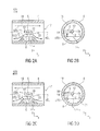
- Fig. 2a shows a third view of the first embodiment of a device 1 according to the invention, wherein a two-dimensional longitudinal sectional view is shown.
- Fig. 2b shows a fourth view of the first embodiment of a device according to the invention, wherein a two-dimensional cross-sectional view of the device 1 of FIG. 2a is shown.
- a gap 14 between the surface 2 and the Strömungsumschelement 6 in at least one direction perpendicular to the main flow line HSL and parallel to the surface 2 to the surface is open.
- the Strömungsumschelement 6 in a section parallel to the main flow line HSL and perpendicular to the surface 2 is symmetrical with respect to a perpendicular to the main flow line HSL axis.
- This feature also contributes to the fact that the characteristic of the flow sensor 10 fails symmetrically. Exemplary such characteristic curves are explained below with reference to FIG.
- the Strömungsumschelement 6 in a section parallel to the main flow line HSL and perpendicular to the surface 2 a trapezoidal shape, with a shorter base side 29 of the trapezoidal shape of the surface 2 faces, preferably one of the shorter base side 29 outgoing side 15 of the trapezoidal shape a parallel to the main flow line HSL extending straight line at an angle ⁇ of at least 20 °, preferably of at least 30 °, more preferably of at least 40 °, and / or of at most 70 °, preferably of at most 60 ° , more preferably of at most 50 °, cuts.
- the trapezoidal design of the Strömungsumschelements 6 facilitates the manufacture of the device and simultaneously achieves a vortex-free abutment of the partial flow on the surface 2 of the sensor 10.
- the speed range in that accurate measurements are possible, is greatest when the from the shorter base side 29 outgoing sides of the trapezoidal shape with respect to the main flow line HSL are employed in a range of 45 °.
- the flow deflection element 6 is arranged in the fluid channel 17 such that a free cross section 18 is present between a side of the sensor chip 5 facing away from the flow deflection element and the wall 4 of the fluid channel.
- a free cross section 18 is present between a side of the sensor chip 5 facing away from the flow deflection element and the wall 4 of the fluid channel.
- the Strömungsumschelement 6 is arranged in the fluid channel 17 that it is part of the Wall 4 forms. In this way, the stability of the device 1 is increased and the production of the same simplified.
- a minimum distance between the surface 2 and the deflection element 6 is at least 0.5 mm, preferably at least 0.6 mm, particularly preferably at least 0.8 mm, and / or at most 2.0 mm, preferably at most 1.5 mm, more preferably at most 1.2 mm.
- the membrane sensor element 12 is formed on a freestanding sensor finger 5.
- the sensor finger 5 is formed by the sensor chip 5 itself.
- the freestanding sensor finger it would also be possible for the freestanding sensor finger to be formed by a carrier for the sensor chip 5, for example made of glass, and by the sensor chip 5.
- the Strömungsumschelement 6 in a section parallel to the main flow line HSL and perpendicular to the surface 2 in a modification to the first embodiment a triangular shape, wherein a tip of the triangular shape of the surface 2 faces, preferably one of the tip of the outgoing side of the triangular shape extending parallel to the main flow line HSL straight line at an angle ⁇ of at least 20 °, preferably of at least 30 °, more preferably of at least 40 °, and / or of at most 70 °, preferably of at most 60 °, more preferably of at most 50 °, cuts.
- the triangular formation of the Strömungsumschelements 6 also facilitates the manufacture of the device and simultaneously achieves a vortex-free abutment of the partial flow on the surface two of the sensor chip 5.
- the speed range in that accurate measurements are possible, is greatest when the sides of the triangular shape starting from the tip are set in a range of 45 ° with respect to the main flow line HSL.
- the deflection element 6 is designed as a modification to the first embodiment as a freestanding deflection finger 6. This also makes it possible to further reduce the energetic influence of the fluid flow FS as well as the risk of condensate formation.
- Fig. 2c shows a fifth view of the first embodiment of a device 1 according to the invention, wherein a two-dimensional longitudinal sectional view is shown.
- Fig. 2d shows a sixth view of the first embodiment of a device according to the invention one, wherein a two-dimensional cross-sectional view of the device 1 of Figure 2c is shown.
- a second flow direction ST2 which is opposite to the first flow direction ST1.
- the flow deflection element 6 is designed such that the partial flow UTS is directed obliquely against the surface 2 in the flow direction ST1 and in an opposite flow direction ST2. In this way, a measurement of the flow parameter VD is possible both when the fluid flows in the first flow direction ST1, and when the fluid in the opposite second flow direction ST2 flows.
- the device is thus suitable for bidirectional measurement.
- the deflection element 6 is viewed along the main flow line HSL viewed centrally to the thermal membrane sensor element 12. This feature contributes to the fact that the characteristic of the flow sensor 10 at least in magnitude in both flow directions ST1 and ST2 runs the same, which simplifies the further processing of the electrical signal of the flow sensor.
- Fig. 3a shows a first view of a second embodiment of a device 1 according to the invention, wherein a two-dimensional longitudinal sectional view is shown.
- Fig. 3b shows a second view of the second embodiment of a device according to the invention, wherein a two-dimensional cross-sectional view is shown.
- the flow deflection element 6 is arranged in the fluid channel 17 such that a free cross section 16 is present between a side of the flow deflection element 6 facing away from the sensor chip 5 and the wall 4 of the fluid channel.
- a sum of the cross-sectional area 20 of the flow sensor 10 in the fluid channel 17 and the cross-sectional area 21 of the deflecting element 6 in the fluid channel 17 in a plane perpendicular to the main flow line HSL is at most 50%, preferably at most 30%, particularly preferably at most 10%, the limited by the wall 4 of the fluid channel 17 cross-sectional area.
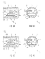
- Fig. 3c shows a first view of a third embodiment of a device according to the invention, wherein a two-dimensional longitudinally-sectioned Illustration is shown. Further shows Fig. 3d a second view of the third embodiment of a device according to the invention, wherein a two-dimensional cross-sectional view is shown.
- a side 26 'of the flow sensor 10 facing the fluid flowing in the first flow direction ST1 and / or a fluid 26' of the flow sensor 10 flowing in the second flow direction ST1 are shaped such that the cross section of the flow sensor 10 Fluid channel 17 in the respective flow direction ST1; ST2 narrowed. In this way, a slight energetic influence of the fluid flow can be achieved, resulting in a low flow resistance and accurate measurement results.
- the third embodiment corresponds to the second embodiment.
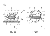
- Fig. 3e shows a first view of a fourth embodiment of a device according to the invention, wherein a two-dimensional longitudinal sectional view is shown. Further shows Fig. 3f a second view of the fourth embodiment of a device according to the invention, wherein a two-dimensional cross-sectional view is shown.
- the fourth embodiment corresponds to the second embodiment.
- the hexagonal shape of the Strömungsumschelements 6 facilitates the manufacture of the device and simultaneously achieves a vortex-free abutment of the partial flow on the surface 2 of the sensor 10. Again, experiments have surprisingly revealed that the speed range in which accurate measurements are possible, then is the greatest when the sides 27 of the hexagonal shape outgoing from the side surface 28 formed parallel to the surface and facing the surface are set in a range of 45 ° with respect to the main flow line HSL.
- the Strömungsumschelement 6 in a section parallel to the main flow line HSL and perpendicular to the surface 2 has a diamond-shaped shape, wherein a tip of the diamond-shaped shape of the surface 2 faces, preferably one of the top outgoing side of the diamond-shaped form a parallel to the main flow line HSL extending straight line at an angle ⁇ of at least 20 °, preferably at least 30 °, more preferably at least 40 °, and / or at most 70 °, preferably at most 60 °, especially preferably of at most 50 °, cuts.
- Fig. 4a shows a first view of a fifth embodiment of a device 1 according to the invention, wherein a two-dimensional longitudinal sectional view is shown.
- Fig. 4b shows a second view of the fifth embodiment of a device 1 according to the invention, wherein a two-dimensional cross-sectional view is shown.
- the sensor chip 5 is arranged in the fluid channel 17 such that it forms part of the wall 4. In this way, the stability of the device is increased and the production of the same simplified.
- Fig. 4c shows a first view of a sixth embodiment of a device according to the invention, wherein a two-dimensional longitudinal sectional view is shown. Further shows Fig. 4d a second view of the sixth embodiment of a device according to the invention, wherein a two-dimensional cross-sectional view is shown.
- a side 26 'of the flow sensor 10 facing the fluid flowing in the first flow direction ST1 and / or a fluid 26' of the flow sensor 10 flowing in the second flow direction ST1 are shaped such that the cross section of the flow sensor 10 Fluid channel 17 in the respective flow direction ST1; ST2 narrowed. In this way, a slight energetic influence of the fluid flow can be achieved, resulting in a low flow resistance and accurate measurement results.
- the sixth embodiment corresponds to the fifth embodiment.
- the flow sensor 10 can have a sensor chip 5 which can be fastened to a measuring head 13 which has corresponding electrical connections 11, wherein during operation of the flow sensor 10 the sensor chip 5 is connected to the thermal membrane sensor element 12 (FIG. FIG. 6 ) is flowed around as free-standing sensor fingers 5 of the fluid flow FS.
- the flow sensor 10 may taper from the measuring head 13 coming to the sensor chip 5.
- the flow sensor 10 with the sensor chip can be flowed around the fluid in the fluid channel 17, as shown in the preceding figures, as a free "nude chip", so as to better a flow parameter of the fluid, eg with a lower error rate, in a larger range or with a higher dynamic range, to be able to determine.
- the flow sensor can be a microelectromechanical semiconductor (MEMS) sensor. That is, the sensor chip 5 may be, for example, a silicon semiconductor chip 5, which has been structured microsystemically. Also conceivable is the use of other semiconductor materials, such as silicon carbide, gallium arsenide, indium phosphide, etc., which are used in semiconductor technology and in microelectromechanics. Glass, ceramic or similar materials can also serve as a substrate for the flow sensor or sensor chip according to the invention.
- MEMS microelectromechanical semiconductor
- Fig. 6 the top view of a sensor chip 5 is shown in a different degree of detail of the individual elements. It shows the Fig. 6a the supervision of a microscope image of the sensor chip 5, and the Fig. 6b a schematic representation of the top view of a membrane 9 and the thermal membrane sensor element 12 with the heaters 3 and the two opposite temperature sensors 7, 7 ', which are each formed as a thermocouple group 7, 7'. Furthermore, in the Fig. 6c a detailed view of a thermocouple group 7 'shown with the series-connected thermocouples.
- the flow sensor 10 has a sensor chip 5, wherein the sensor chip 5 has at least one thermal membrane sensor element 12, which is designed to determine a flow parameter VD of the fluid. In addition, it may additionally be configured to determine a fluid temperature, for example a relative fluid temperature or an absolute fluid temperature.
- the thermal membrane sensor element 12 has two temperature sensors 7, 7 '. These temperature sensors 7, 7 'may be, for example, thermocouples 8, 8', resistance strips, for example with platinum or nickel, or groups of thermocouples 7, 7 ', so-called thermopiles 7, 7'.
- the thermal membrane sensor element 12 has a membrane, the two spaced-apart temperature sensor 7, 7 'and between the temperature sensor 7, 7' arranged Heating element 3 has.
- the sensor chip 5 thus has a thermal membrane sensor element 12 with two spaced-apart temperature sensors 7, 7 '.
- the sensor chip 5 may, as in the Fig. 6a is shown to act an elongated sensor finger 5, in which, for example, the longitudinal side L is 6 mm and the width W 2 mm. In some embodiments, therefore, a longitudinal edge of the sensor finger or the sensor chip 5 three times or even longer than the narrow side W of the sensor finger or the sensor chip 5 to the sensitive element 12 in the flow FS freestanding and outside of the flow disturbing transition to the mechanical anchoring of Positioning head 13 to place.
- the electrical leads 19 are located on an end face of the sensor finger or the sensor chip 5 and are there with the measuring head (not shown in FIG Fig. 6a ) connected.
- the active sensory elements 12 may be arranged in the first third of the surface 2 of the sensor finger 5 at the free end 5a of the sensor finger 5. As a result, a flow measurement is influenced as little as possible by the connection to the fuselage or measuring head 13 of the flow sensor 10.
- thermocouples 8 and 8 ' are interconnected on their respective side in series and combined into a respective thermopile 7, 7'.
- the individual thermocouples 8 and 8 'and the thermopiles 7, 7' each have thermocouple junctions 8a and 8b, which are arranged on the sensor membrane 9 and respectively associated second thermocouple junctions 8c and 8d, which are arranged on the chip frame or the Siliziumbulk. Both the heating elements 3 and the thermocouples 8, 8 'have corresponding electrical leads 19.
- thermocouple junctions 8b, 8d are arranged on the membrane 9, and on the other hand, the thermocouple junctions 8d, which also polysilicon 25 and aluminum 24, and which are formed on the Siliziumbulk or sensor chip frame.
- thermocouple junctions 8b of the thermopile 7 are 'a higher temperature T have hot as the associated thermocouple junctions 8d of the thermopile 7', which have a lower temperature T cold.
- the membrane 9 has a low thermal mass, so that when heating the heating element, the membrane 9 will relatively quickly assume the temperature generated by the heater, whereas the temperature on the silicon chip or the sensor chip frame will be lower.
- an extension L of the sensor chip or of the sensor finger 5 in a direction perpendicular to the main flow line HSL and parallel to the surface 2 is at least three times as large, preferably four times as large, particularly preferably five times as large, as an extension W of the sensor chip 5 or sensor finger 5 in a direction parallel to the main flow line HSL.
- the sensor chip 5 or sensor fingers 5 may be an elongated sensor chip 5 or sensor fingers 5, in which, for example, the longitudinal side running perpendicular to the main flow line and parallel to the surface is 6 mm and the width extending parallel to the main flow line is 2 mm.
- a longitudinal edge of the sensor chip 5 or sensor finger 5 three times or even longer than the narrow side W of the sensor chip or sensor finger to the sensitive elements 12 in the flow freestanding and outside the flow disturbing transition to the mechanical anchoring of the sensor chip or Sensorfingers 5 to place.
- the membrane sensor element 12 is arranged in a first third of the surface 2 at a free end 5a of the sensor chip 5 or sensor finger 5, the free end 5a of the sensor chip 5 or sensor finger 5 a second end 5b of the sensor chip 5 or of the sensor finger 5, on which electrical supply lines 19 are connected to the sensor chip 5 or to the sensor finger 5.
- the active sensory elements 12 may be arranged in the first third of the chip area 2 at the free end 5a of the sensor chip 5 or sensor chip 5.
- Fig. 7 is the principle of operation of a thermal flow sensor 5 in a diagram from the dissertation by Sven Zinober, "Redundancy structures to increase the safety and reliability of microsystems", Dissertation, Albert-Ludwig University Freiburg im Breisgau, 2002 shown.
- the solid curve in Fig. 7 shows the schematic temperature profile along a fluid channel wall 4 on a sensor surface 2 for a resting medium or fluid and the dashed curve at an assumed flow of a fluid in the direction indicated by the arrow flow direction ST1 from left to right.
- thermocouples 8 and 8 ' In a quiescent medium forms when heating the sensor membrane at the point X 0 through the heater 3, a uniform decaying temperature distribution in the direction of the thermocouples 8 and 8 'from. That is, in a static flow is measured at an identical distance -X 1 and + X 1 of the thermocouples 8 and 8 'of the heater 3, an identical temperature. So rested the flow medium, the active sensor surface is heated by heat conduction in the membrane and in the medium. The corresponding temperature is thus detected by the thermocouples 8, 8 '. With an onset of flow in the direction indicated by the arrow flow direction then forms a temperature distribution as shown by the dashed curve. In the case of flow, therefore, the heat distribution field is displaced in the direction of the thermocouple 8 'facing away from the flow.
- Fig. 7 So shows the schematic temperature profile on the sensor plane with the two thermocouples 8,8 'and the interposed heater 3 and the displacement of this course in dependence on the flow velocity of the fluid flowing over it
- the heater 3 is heated to a constant temperature (also referred to as constant temperature anemometry, CTA).
- CTA constant temperature anemometry
- the heater 3 can also be heated in different ways, ie with constant power, constant voltage or constant current (constant current anemometry, CCA), or eg periodically or pulsed.
- a measuring head with a freestanding sensor finger can thus be arranged in a flowing fluid such that the flowing fluid first flows around a first thermocouple 8, then flows around the heater 3 and further the second thermocouple 8 '.
- the temperature differences .DELTA.T 1 and .DELTA.T 2 give the difference between the respective hot contacts 8a, 8b of the thermocouples 8, 8 'facing the heater 3 and the ends 8c, 8d of the thermocouples 8, 8' facing away from the heater 3, which are located on the silicon core and thus can be referred to as cold contact.
- ⁇ T 1 is the temperature difference at the upstream (upstream) sensor 8 and ⁇ T 2 at the downstream (downstream) sensor 8 '. If the flow medium is at rest, the active sensor surface is heated by heat conduction in the membrane and the medium. When the flow starts, here in the flow direction from left to right, this heat distribution field is shifted to the right.
- thermocouples 8, 8 ' can again be connected in series with thermopiles 7, 7'.
- the flow medium or fluid thus initially reaches the upstream thermopile 7, cools it, is then heated at the heater 3 and carries this heat with you.
- the hot contacts 8b of the flow-downstream downstream thermopile 7 ' are heated more strongly.
- the difference of the temperature differences at the thermopiles 7, 7 ', ie .DELTA.T 2 - .DELTA.T 1 is then dependent on the flow rate temperature difference between the downstream thermopile 7' and the upstream thermopile 7. So it can the temperature profile between the membrane center with the Heater and the Siliziumbulk be measured.
- flow sensors 10 with high dynamics, e.g. from 1:10 to 1: 10,000, e.g. So build from 1: 1000.
- the flow sensor 10 should have a dense passivation of the thermopile structures and their feed lines so as to avoid an electrical short circuit of the active sensor elements.
- the flow sensor 10 is for gases and liquids or generally fluids, e.g. can be used both in an anemometer and in a calorimeter operation.
- the Fig. 8 shows a diagram of simulatively determined characteristics different embodiments of the device according to the invention.
- FIG. 8 1 shows the values of the electrical signal ⁇ TP in millivolts (mV) of a flow sensor 10 of an exemplary device 1 as a function of a volume flow rate VD in standard liters per minute (slpm), which corresponds to a function ⁇ TP (VD).
- the values of the electrical signal .DELTA.TP are shown as a difference to a value measured without flow.
- a first characteristic .DELTA.TP1 relates to a simulation of the device 1 of the first embodiment, wherein the flanks of the trapezoidal deflection element 6 are employed by 45 °.
- a second characteristic .DELTA.TP2 refers to a simulation of the device 1 of the first embodiment, wherein the flanks of the trapezoidal deflecting element 6 to 21 ° are employed.
- a right side of the diagram applies to the case in which the fluid flow FS flows in the first flow direction ST1.
- a right side of the diagram applies in the case where the fluid flow FS flows in the counter-flow direction ST2.
- the direction is represented by the sign of the volume flow rate VD and the electrical signal ⁇ TP.
- the characteristic curves ⁇ TP1 and ⁇ TP2 are substantially point-symmetrical with respect to the zero point.
- the measuring range for a deflecting element 6 with flanks set at 21 ° only ranges from about -125 slpm to about +125 slpm, the measuring range for a deflecting element 6 extends with flanks set at 45 ° from about -300 slpm to about +300 slpm ,
- the measuring range is that range in which a unique inverse function VD ( ⁇ TP) can be formed from the function ⁇ TP (VD).
- the present invention comprises in one embodiment a device 1 with a directed flow of the free-standing sensor finger 5 for the bidirectional measurement of moist gases in the main flow FS, which is located in an externally straight measuring channel 17, which is currently preferred in practice as a flow measuring device 1.
- the measuring section can contribute to a smoothing of the flow profile, which can be achieved, for example, by narrowing the tube cross-section in Venturi form and by installing additional flow rectifiers, such as grids, sieves or honeycomb structures.
- the following solution for installing the sensor finger is proposed in a straight tube: unilateral narrowing of the flow channel by a wedge-shaped edge with 45 ° flanks, which generates a directed column flow above its trailing edge.
- the sensor finger 5 which is longitudinal to the main flow FS, can be placed symmetrically and plane-parallel to its longitudinal axis, so that its sensitive surface 2 is flowed in a defined manner with the medium deflected obliquely over the flank.
- the desired column flow UTS is achieved via the sensor 5, without influencing the main flow FS too strongly, for example by means of a 90 ° deflection (energetic), and generating undesired turbulence.
- the measuring device proposed here has no side walls, which could retain (water) drops capillary. Instead, drops may run out or drip off in the laterally open structure.
- the thermal mass remains reduced to the minimum, since only a part of the sensor chip is in the housing, so that a low thermal power is sufficient to temper the sensor above the dew point.
- the measuring device 1 for determining a flow parameter VD of a fluid FS may have the following features: Center-symmetrical placement of a (preferably) wedge-shaped flow guide 6 over the sensitive elements 12 of a flow sensor 10, which is suitable for generating the desired plane-parallel column flow UTS over the boundary layer of the sensor surface 2; wherein the flow guide 6 can be designed so that it flows bidirectionally in both pipe directions ST1, ST2 and can generate the column flow over the sensor chip 5; wherein the flow guide can have 45 ° inclined flanks, but can also be designed as a further advantageous flow body such as round or oval profile corresponding to the required flow measuring range, wherein the flow guide 6 can be installed with the side facing away from the sensor 10 in the smooth channel wall 4 and thus accelerate and align the main flow FS in the sense of a (one-side) channel constriction, wherein the flow guide 6 can also be arranged freestanding in the middle of the channel as a bypass in the main channel 17 together with the sensor chip 5 and thus can be a separate sensory assembly, wherein the
Landscapes
- Physics & Mathematics (AREA)
- Fluid Mechanics (AREA)
- General Physics & Mathematics (AREA)
- Measuring Volume Flow (AREA)
Applications Claiming Priority (1)
| Application Number | Priority Date | Filing Date | Title |
|---|---|---|---|
| DE102013223372.8A DE102013223372A1 (de) | 2013-11-15 | 2013-11-15 | Vorrichtung zur bestimmung eines strömungsparameters eines fluidstroms |
Publications (3)
| Publication Number | Publication Date |
|---|---|
| EP2889587A2 true EP2889587A2 (fr) | 2015-07-01 |
| EP2889587A3 EP2889587A3 (fr) | 2015-12-09 |
| EP2889587B1 EP2889587B1 (fr) | 2024-10-23 |
Family
ID=51986995
Family Applications (1)
| Application Number | Title | Priority Date | Filing Date |
|---|---|---|---|
| EP14193344.0A Active EP2889587B1 (fr) | 2013-11-15 | 2014-11-14 | Dispositif de détermination d'un paramètre d'écoulement d'un flux de liquide |
Country Status (2)
| Country | Link |
|---|---|
| EP (1) | EP2889587B1 (fr) |
| DE (1) | DE102013223372A1 (fr) |
Cited By (2)
| Publication number | Priority date | Publication date | Assignee | Title |
|---|---|---|---|---|
| JP2017053787A (ja) * | 2015-09-11 | 2017-03-16 | 株式会社デンソー | 空気流量測定装置 |
| US11959787B2 (en) | 2021-03-02 | 2024-04-16 | Honeywell International Inc. | Flow sensing device |
Families Citing this family (2)
| Publication number | Priority date | Publication date | Assignee | Title |
|---|---|---|---|---|
| DE102015212142B4 (de) | 2015-06-30 | 2017-08-10 | Hahn-Schickard-Gesellschaft für angewandte Forschung e.V. | Vorrichtung, Verfahren und maschinenlesbare Befehle zum Steuern eines graphischen Objekts auf einem Anzeigegerät |
| DE102015118120A1 (de) | 2015-10-23 | 2017-04-27 | Endress + Hauser Flowtec Ag | Thermisches Durchflussmessgerät und Anordnung mit einem Rohr und dem thermischen Durchflussmessgerät |
Citations (1)
| Publication number | Priority date | Publication date | Assignee | Title |
|---|---|---|---|---|
| WO2013030198A1 (fr) | 2011-08-31 | 2013-03-07 | Hahn-Schickard-Gesellschaft für angewandte Forschung e.V. | Capteur d'écoulement pour déterminer un paramètre d'écoulement et procédé pour déterminer ledit paramètre |
Family Cites Families (10)
| Publication number | Priority date | Publication date | Assignee | Title |
|---|---|---|---|---|
| GB1512290A (en) * | 1975-11-24 | 1978-06-01 | Agar J Instrumentation Ltd | Method and apparatus for determining fluid flow rate and/or for exercising a control in dependence thereon |
| US5631417A (en) * | 1995-09-06 | 1997-05-20 | General Motors Corporation | Mass air flow sensor structure with bi-directional airflow incident on a sensing device at an angle |
| JP4811695B2 (ja) * | 2000-05-30 | 2011-11-09 | 株式会社デンソー | 流量測定装置 |
| JP2002333347A (ja) * | 2001-05-08 | 2002-11-22 | Ngk Spark Plug Co Ltd | 分流式流量計 |
| US6938473B2 (en) * | 2001-11-19 | 2005-09-06 | Denso Corporation | Apparatus for measuring flow amount |
| JP4106224B2 (ja) * | 2002-03-14 | 2008-06-25 | 株式会社デンソー | 流量測定装置 |
| JP4073324B2 (ja) * | 2003-01-24 | 2008-04-09 | 株式会社日立製作所 | 熱式流量測定装置 |
| JP4317556B2 (ja) * | 2006-07-21 | 2009-08-19 | 株式会社日立製作所 | 熱式流量センサ |
| JP5178148B2 (ja) * | 2007-10-31 | 2013-04-10 | 日立オートモティブシステムズ株式会社 | 発熱抵抗体式空気流量測定装置 |
| JP5425021B2 (ja) * | 2010-09-06 | 2014-02-26 | 日立オートモティブシステムズ株式会社 | 流量測定装置 |
-
2013
- 2013-11-15 DE DE102013223372.8A patent/DE102013223372A1/de active Granted
-
2014
- 2014-11-14 EP EP14193344.0A patent/EP2889587B1/fr active Active
Patent Citations (1)
| Publication number | Priority date | Publication date | Assignee | Title |
|---|---|---|---|---|
| WO2013030198A1 (fr) | 2011-08-31 | 2013-03-07 | Hahn-Schickard-Gesellschaft für angewandte Forschung e.V. | Capteur d'écoulement pour déterminer un paramètre d'écoulement et procédé pour déterminer ledit paramètre |
Non-Patent Citations (1)
| Title |
|---|
| REDUNDANZSTRUKTUREN ZUR ERHÖHUNG DER SICHERHEIT UND ZUVERLÄSSIGKEIT VON MIKROSYSTEMEN, DISSERTATION, ALBERT-LUDWIG-UNIVERSITÄT FREIBURG I. BREISGAU, 9 July 2002 (2002-07-09) |
Cited By (2)
| Publication number | Priority date | Publication date | Assignee | Title |
|---|---|---|---|---|
| JP2017053787A (ja) * | 2015-09-11 | 2017-03-16 | 株式会社デンソー | 空気流量測定装置 |
| US11959787B2 (en) | 2021-03-02 | 2024-04-16 | Honeywell International Inc. | Flow sensing device |
Also Published As
| Publication number | Publication date |
|---|---|
| EP2889587B1 (fr) | 2024-10-23 |
| DE102013223372A1 (de) | 2015-05-21 |
| EP2889587A3 (fr) | 2015-12-09 |
Similar Documents
| Publication | Publication Date | Title |
|---|---|---|
| EP2869041B1 (fr) | Capteur de flux destiné à la détermination d'un paramètre d'écoulement et son procédé de détermination | |
| DE102011081923B4 (de) | Sensorchip zur Bestimmung eines Strömungsparameters eines Gases und Verfahren zur Bestimmung desselben | |
| EP2889587B1 (fr) | Dispositif de détermination d'un paramètre d'écoulement d'un flux de liquide | |
| EP1556670B1 (fr) | Debitmetre a tourbillons | |
| DE102012109237A1 (de) | Durchflussmessgerät, sowie Verwendung dieses Durchflussgerätes und Verfahren zur Ermittlung der Fließgeschwindigkeit | |
| CH666751A5 (de) | Waermeleistungs- und/oder massendurchflussmesser. | |
| WO2019048210A1 (fr) | Débitmètre thermique | |
| DE19750594A1 (de) | Wärmeempfindlicher Durchflußmesser | |
| DE102007037394A1 (de) | Vorrichtung zur Bestimmung und/oder Überwachung des Durchflusses eines Messmediums durch eine Rohrleitung bzw. durch ein Messrohr | |
| DE102019103674A1 (de) | Durchflussmessanordnung und strömungstechnische Anordnung | |
| DE102014119231B4 (de) | Thermisches Durchflussmessgerät mit Diagnosefunktion sowie zugehöriges Betriebsverfahren | |
| DE102012001573A1 (de) | Verfahren zum Messen einer Durchflussmenge eines strömenden Gases | |
| WO1998022784A1 (fr) | Procede et dispositif pour la mesure autocompensee du debit volumetrique de gaz | |
| DE19908664A1 (de) | Gaszähler | |
| WO1995011427A1 (fr) | Procede et dispositif pour la determination, notamment non invasive, d'au moins un parametre interessant d'un systeme fluide/tuyau | |
| DE4205207A1 (de) | Vorrichtung zur messung einer gas- oder fluessigkeitsstroemung | |
| WO2002095338A2 (fr) | Capteur pour mesurer des vitesses d'ecoulement et procede pour faire fonctionner ce capteur | |
| DE10334239A1 (de) | Fluidischer Flusssensor | |
| EP4396540A1 (fr) | Procédé de détection de bulles ou de gouttelettes d'un premier milieu dans un deuxième milieu fluide traversant un tube de mesure | |
| DE102012109234A1 (de) | Durchflussmessgerät, sowie Verwendung dieses Durchflussgerätes und Verfahren zur Ermittlung der Fließgeschwindigkeit | |
| DE102009033420B4 (de) | Vorrichtung zum Bestimmen des Sauerstoffgehalts in einem Gas | |
| DE102005028143B4 (de) | Thermischer Luftmassenmesser mit geringer Kontaminationsempfindlichkeit | |
| DE112004000842T5 (de) | Vorrichtung und Verfahren zur thermischen anemometrischen Massenstrom-Messung | |
| DE7539850U (de) | Durchflussmessgeber | |
| DE19716897C1 (de) | Dosiervorrichtung |
Legal Events
| Date | Code | Title | Description |
|---|---|---|---|
| PUAI | Public reference made under article 153(3) epc to a published international application that has entered the european phase |
Free format text: ORIGINAL CODE: 0009012 |
|
| 17P | Request for examination filed |
Effective date: 20141114 |
|
| AK | Designated contracting states |
Kind code of ref document: A2 Designated state(s): AL AT BE BG CH CY CZ DE DK EE ES FI FR GB GR HR HU IE IS IT LI LT LU LV MC MK MT NL NO PL PT RO RS SE SI SK SM TR |
|
| AX | Request for extension of the european patent |
Extension state: BA ME |
|
| PUAL | Search report despatched |
Free format text: ORIGINAL CODE: 0009013 |
|
| AK | Designated contracting states |
Kind code of ref document: A3 Designated state(s): AL AT BE BG CH CY CZ DE DK EE ES FI FR GB GR HR HU IE IS IT LI LT LU LV MC MK MT NL NO PL PT RO RS SE SI SK SM TR |
|
| AX | Request for extension of the european patent |
Extension state: BA ME |
|
| RAP1 | Party data changed (applicant data changed or rights of an application transferred) |
Owner name: KARL KUEFNER GMBH & CO. KG Owner name: HAHN-SCHICKARD-GESELLSCHAFT FUER ANGEWANDTE FORSCH |
|
| RIC1 | Information provided on ipc code assigned before grant |
Ipc: G01F 1/684 20060101AFI20151105BHEP Ipc: G01F 1/692 20060101ALI20151105BHEP |
|
| R17P | Request for examination filed (corrected) |
Effective date: 20160609 |
|
| RBV | Designated contracting states (corrected) |
Designated state(s): AL AT BE BG CH CY CZ DE DK EE ES FI FR GB GR HR HU IE IS IT LI LT LU LV MC MK MT NL NO PL PT RO RS SE SI SK SM TR |
|
| RIN1 | Information on inventor provided before grant (corrected) |
Inventor name: KATTINGER, GERHARD Inventor name: BILLAT, SOPHIE Inventor name: BRONNER, RALF Inventor name: STORZ, MATTHIAS Inventor name: HEDRICH, FRANK |
|
| STAA | Information on the status of an ep patent application or granted ep patent |
Free format text: STATUS: EXAMINATION IS IN PROGRESS |
|
| 17Q | First examination report despatched |
Effective date: 20190509 |
|
| RAP1 | Party data changed (applicant data changed or rights of an application transferred) |
Owner name: HAHN-SCHICKARD-GESELLSCHAFT FUER ANGEWANDTE FORSCHUNG E.V. Owner name: GS ELEKTROMEDIZINISCHE GERAETE G. STEMPLE GMBH |
|
| GRAP | Despatch of communication of intention to grant a patent |
Free format text: ORIGINAL CODE: EPIDOSNIGR1 |
|
| STAA | Information on the status of an ep patent application or granted ep patent |
Free format text: STATUS: GRANT OF PATENT IS INTENDED |
|
| INTG | Intention to grant announced |
Effective date: 20240517 |
|
| RAP3 | Party data changed (applicant data changed or rights of an application transferred) |
Owner name: GS ELEKTROMEDIZINISCHE GERAETE G. STEMPLE GMBH Owner name: HAHN-SCHICKARD-GESELLSCHAFT FUER ANGEWANDTE FORSCHUNG E. V. |
|
| GRAS | Grant fee paid |
Free format text: ORIGINAL CODE: EPIDOSNIGR3 |
|
| GRAA | (expected) grant |
Free format text: ORIGINAL CODE: 0009210 |
|
| STAA | Information on the status of an ep patent application or granted ep patent |
Free format text: STATUS: THE PATENT HAS BEEN GRANTED |
|
| P01 | Opt-out of the competence of the unified patent court (upc) registered |
Free format text: CASE NUMBER: APP_50706/2024 Effective date: 20240906 |
|
| AK | Designated contracting states |
Kind code of ref document: B1 Designated state(s): AL AT BE BG CH CY CZ DE DK EE ES FI FR GB GR HR HU IE IS IT LI LT LU LV MC MK MT NL NO PL PT RO RS SE SI SK SM TR |
|
| REG | Reference to a national code |
Ref country code: GB Ref legal event code: FG4D Free format text: NOT ENGLISH |
|
| REG | Reference to a national code |
Ref country code: CH Ref legal event code: EP |
|
| REG | Reference to a national code |
Ref country code: DE Ref legal event code: R096 Ref document number: 502014016882 Country of ref document: DE |
|
| REG | Reference to a national code |
Ref country code: IE Ref legal event code: FG4D Free format text: LANGUAGE OF EP DOCUMENT: GERMAN |
|
| REG | Reference to a national code |
Ref country code: NL Ref legal event code: FP |
|
| REG | Reference to a national code |
Ref country code: SE Ref legal event code: TRGR |
|
| REG | Reference to a national code |
Ref country code: LT Ref legal event code: MG9D |
|
| PG25 | Lapsed in a contracting state [announced via postgrant information from national office to epo] |
Ref country code: PT Free format text: LAPSE BECAUSE OF FAILURE TO SUBMIT A TRANSLATION OF THE DESCRIPTION OR TO PAY THE FEE WITHIN THE PRESCRIBED TIME-LIMIT Effective date: 20250224 Ref country code: IS Free format text: LAPSE BECAUSE OF FAILURE TO SUBMIT A TRANSLATION OF THE DESCRIPTION OR TO PAY THE FEE WITHIN THE PRESCRIBED TIME-LIMIT Effective date: 20250223 Ref country code: HR Free format text: LAPSE BECAUSE OF FAILURE TO SUBMIT A TRANSLATION OF THE DESCRIPTION OR TO PAY THE FEE WITHIN THE PRESCRIBED TIME-LIMIT Effective date: 20241023 |
|
| PG25 | Lapsed in a contracting state [announced via postgrant information from national office to epo] |
Ref country code: FI Free format text: LAPSE BECAUSE OF FAILURE TO SUBMIT A TRANSLATION OF THE DESCRIPTION OR TO PAY THE FEE WITHIN THE PRESCRIBED TIME-LIMIT Effective date: 20241023 |
|
| PG25 | Lapsed in a contracting state [announced via postgrant information from national office to epo] |
Ref country code: BG Free format text: LAPSE BECAUSE OF FAILURE TO SUBMIT A TRANSLATION OF THE DESCRIPTION OR TO PAY THE FEE WITHIN THE PRESCRIBED TIME-LIMIT Effective date: 20241023 |
|
| PG25 | Lapsed in a contracting state [announced via postgrant information from national office to epo] |
Ref country code: ES Free format text: LAPSE BECAUSE OF FAILURE TO SUBMIT A TRANSLATION OF THE DESCRIPTION OR TO PAY THE FEE WITHIN THE PRESCRIBED TIME-LIMIT Effective date: 20241023 |
|
| PG25 | Lapsed in a contracting state [announced via postgrant information from national office to epo] |
Ref country code: NO Free format text: LAPSE BECAUSE OF FAILURE TO SUBMIT A TRANSLATION OF THE DESCRIPTION OR TO PAY THE FEE WITHIN THE PRESCRIBED TIME-LIMIT Effective date: 20250123 |
|
| PG25 | Lapsed in a contracting state [announced via postgrant information from national office to epo] |
Ref country code: LV Free format text: LAPSE BECAUSE OF FAILURE TO SUBMIT A TRANSLATION OF THE DESCRIPTION OR TO PAY THE FEE WITHIN THE PRESCRIBED TIME-LIMIT Effective date: 20241023 Ref country code: GR Free format text: LAPSE BECAUSE OF FAILURE TO SUBMIT A TRANSLATION OF THE DESCRIPTION OR TO PAY THE FEE WITHIN THE PRESCRIBED TIME-LIMIT Effective date: 20250124 |
|
| PG25 | Lapsed in a contracting state [announced via postgrant information from national office to epo] |
Ref country code: PL Free format text: LAPSE BECAUSE OF FAILURE TO SUBMIT A TRANSLATION OF THE DESCRIPTION OR TO PAY THE FEE WITHIN THE PRESCRIBED TIME-LIMIT Effective date: 20241023 |
|
| PG25 | Lapsed in a contracting state [announced via postgrant information from national office to epo] |
Ref country code: RS Free format text: LAPSE BECAUSE OF FAILURE TO SUBMIT A TRANSLATION OF THE DESCRIPTION OR TO PAY THE FEE WITHIN THE PRESCRIBED TIME-LIMIT Effective date: 20250123 |
|
| REG | Reference to a national code |
Ref country code: CH Ref legal event code: PL |
|
| PG25 | Lapsed in a contracting state [announced via postgrant information from national office to epo] |
Ref country code: SM Free format text: LAPSE BECAUSE OF FAILURE TO SUBMIT A TRANSLATION OF THE DESCRIPTION OR TO PAY THE FEE WITHIN THE PRESCRIBED TIME-LIMIT Effective date: 20241023 |
|
| PG25 | Lapsed in a contracting state [announced via postgrant information from national office to epo] |
Ref country code: MC Free format text: LAPSE BECAUSE OF FAILURE TO SUBMIT A TRANSLATION OF THE DESCRIPTION OR TO PAY THE FEE WITHIN THE PRESCRIBED TIME-LIMIT Effective date: 20241023 |
|
| PG25 | Lapsed in a contracting state [announced via postgrant information from national office to epo] |
Ref country code: DK Free format text: LAPSE BECAUSE OF FAILURE TO SUBMIT A TRANSLATION OF THE DESCRIPTION OR TO PAY THE FEE WITHIN THE PRESCRIBED TIME-LIMIT Effective date: 20241023 |
|
| PG25 | Lapsed in a contracting state [announced via postgrant information from national office to epo] |
Ref country code: LU Free format text: LAPSE BECAUSE OF NON-PAYMENT OF DUE FEES Effective date: 20241114 |
|
| REG | Reference to a national code |
Ref country code: CH Ref legal event code: PL |
|
| PG25 | Lapsed in a contracting state [announced via postgrant information from national office to epo] |
Ref country code: EE Free format text: LAPSE BECAUSE OF FAILURE TO SUBMIT A TRANSLATION OF THE DESCRIPTION OR TO PAY THE FEE WITHIN THE PRESCRIBED TIME-LIMIT Effective date: 20241023 |
|
| PG25 | Lapsed in a contracting state [announced via postgrant information from national office to epo] |
Ref country code: CH Free format text: LAPSE BECAUSE OF NON-PAYMENT OF DUE FEES Effective date: 20241130 |
|
| PG25 | Lapsed in a contracting state [announced via postgrant information from national office to epo] |
Ref country code: RO Free format text: LAPSE BECAUSE OF FAILURE TO SUBMIT A TRANSLATION OF THE DESCRIPTION OR TO PAY THE FEE WITHIN THE PRESCRIBED TIME-LIMIT Effective date: 20241023 |
|
| REG | Reference to a national code |
Ref country code: DE Ref legal event code: R097 Ref document number: 502014016882 Country of ref document: DE |
|
| PG25 | Lapsed in a contracting state [announced via postgrant information from national office to epo] |
Ref country code: SK Free format text: LAPSE BECAUSE OF FAILURE TO SUBMIT A TRANSLATION OF THE DESCRIPTION OR TO PAY THE FEE WITHIN THE PRESCRIBED TIME-LIMIT Effective date: 20241023 |
|
| PG25 | Lapsed in a contracting state [announced via postgrant information from national office to epo] |
Ref country code: CZ Free format text: LAPSE BECAUSE OF FAILURE TO SUBMIT A TRANSLATION OF THE DESCRIPTION OR TO PAY THE FEE WITHIN THE PRESCRIBED TIME-LIMIT Effective date: 20241023 |
|
| PG25 | Lapsed in a contracting state [announced via postgrant information from national office to epo] |
Ref country code: IT Free format text: LAPSE BECAUSE OF FAILURE TO SUBMIT A TRANSLATION OF THE DESCRIPTION OR TO PAY THE FEE WITHIN THE PRESCRIBED TIME-LIMIT Effective date: 20241023 |
|
| REG | Reference to a national code |
Ref country code: BE Ref legal event code: MM Effective date: 20241130 |
|
| PLBE | No opposition filed within time limit |
Free format text: ORIGINAL CODE: 0009261 |
|
| STAA | Information on the status of an ep patent application or granted ep patent |
Free format text: STATUS: NO OPPOSITION FILED WITHIN TIME LIMIT |
|
| 26N | No opposition filed |
Effective date: 20250724 |
|
| PG25 | Lapsed in a contracting state [announced via postgrant information from national office to epo] |
Ref country code: BE Free format text: LAPSE BECAUSE OF NON-PAYMENT OF DUE FEES Effective date: 20241130 |
|
| PGFP | Annual fee paid to national office [announced via postgrant information from national office to epo] |
Ref country code: NL Payment date: 20251119 Year of fee payment: 12 |
|
| PGFP | Annual fee paid to national office [announced via postgrant information from national office to epo] |
Ref country code: DE Payment date: 20251118 Year of fee payment: 12 |
|
| PGFP | Annual fee paid to national office [announced via postgrant information from national office to epo] |
Ref country code: GB Payment date: 20251120 Year of fee payment: 12 |
|
| PG25 | Lapsed in a contracting state [announced via postgrant information from national office to epo] |
Ref country code: AT Free format text: LAPSE BECAUSE OF NON-PAYMENT OF DUE FEES Effective date: 20241114 |
|
| PGFP | Annual fee paid to national office [announced via postgrant information from national office to epo] |
Ref country code: FR Payment date: 20251125 Year of fee payment: 12 |
|
| REG | Reference to a national code |
Ref country code: AT Ref legal event code: MM01 Ref document number: 1735193 Country of ref document: AT Kind code of ref document: T Effective date: 20241114 |
|
| PGFP | Annual fee paid to national office [announced via postgrant information from national office to epo] |
Ref country code: SE Payment date: 20251119 Year of fee payment: 12 |
|
| PGFP | Annual fee paid to national office [announced via postgrant information from national office to epo] |
Ref country code: IE Payment date: 20251120 Year of fee payment: 12 |
|
| PG25 | Lapsed in a contracting state [announced via postgrant information from national office to epo] |
Ref country code: HU Free format text: LAPSE BECAUSE OF FAILURE TO SUBMIT A TRANSLATION OF THE DESCRIPTION OR TO PAY THE FEE WITHIN THE PRESCRIBED TIME-LIMIT; INVALID AB INITIO Effective date: 20141114 |
|
| PG25 | Lapsed in a contracting state [announced via postgrant information from national office to epo] |
Ref country code: CY Free format text: LAPSE BECAUSE OF FAILURE TO SUBMIT A TRANSLATION OF THE DESCRIPTION OR TO PAY THE FEE WITHIN THE PRESCRIBED TIME-LIMIT; INVALID AB INITIO Effective date: 20141114 |