EP2889657A2 - Beleuchtungsvorrichtung mit linienförmigem Strahl - Google Patents
Beleuchtungsvorrichtung mit linienförmigem Strahl Download PDFInfo
- Publication number
- EP2889657A2 EP2889657A2 EP14200279.9A EP14200279A EP2889657A2 EP 2889657 A2 EP2889657 A2 EP 2889657A2 EP 14200279 A EP14200279 A EP 14200279A EP 2889657 A2 EP2889657 A2 EP 2889657A2
- Authority
- EP
- European Patent Office
- Prior art keywords
- light source
- light
- lighting device
- guide portion
- light guide
- Prior art date
- Legal status (The legal status is an assumption and is not a legal conclusion. Google has not performed a legal analysis and makes no representation as to the accuracy of the status listed.)
- Granted
Links
Images



Classifications
-
- F—MECHANICAL ENGINEERING; LIGHTING; HEATING; WEAPONS; BLASTING
- F21—LIGHTING
- F21V—FUNCTIONAL FEATURES OR DETAILS OF LIGHTING DEVICES OR SYSTEMS THEREOF; STRUCTURAL COMBINATIONS OF LIGHTING DEVICES WITH OTHER ARTICLES, NOT OTHERWISE PROVIDED FOR
- F21V13/00—Producing particular characteristics or distribution of the light emitted by means of a combination of elements specified in two or more of main groups F21V1/00 - F21V11/00
- F21V13/02—Combinations of only two kinds of elements
- F21V13/04—Combinations of only two kinds of elements the elements being reflectors and refractors
-
- G—PHYSICS
- G02—OPTICS
- G02B—OPTICAL ELEMENTS, SYSTEMS OR APPARATUS
- G02B6/00—Light guides; Structural details of arrangements comprising light guides and other optical elements, e.g. couplings
- G02B6/0001—Light guides; Structural details of arrangements comprising light guides and other optical elements, e.g. couplings specially adapted for lighting devices or systems
- G02B6/0011—Light guides; Structural details of arrangements comprising light guides and other optical elements, e.g. couplings specially adapted for lighting devices or systems the light guides being planar or of plate-like form
- G02B6/0033—Means for improving the coupling-out of light from the light guide
- G02B6/0035—Means for improving the coupling-out of light from the light guide provided on the surface of the light guide or in the bulk of it
- G02B6/0038—Linear indentations or grooves, e.g. arc-shaped grooves or meandering grooves, extending over the full length or width of the light guide
-
- B—PERFORMING OPERATIONS; TRANSPORTING
- B60—VEHICLES IN GENERAL
- B60Q—ARRANGEMENT OF SIGNALLING OR LIGHTING DEVICES, THE MOUNTING OR SUPPORTING THEREOF OR CIRCUITS THEREFOR, FOR VEHICLES IN GENERAL
- B60Q3/00—Arrangement of lighting devices for vehicle interiors; Lighting devices specially adapted for vehicle interiors
- B60Q3/60—Arrangement of lighting devices for vehicle interiors; Lighting devices specially adapted for vehicle interiors characterised by optical aspects
- B60Q3/62—Arrangement of lighting devices for vehicle interiors; Lighting devices specially adapted for vehicle interiors characterised by optical aspects using light guides
- B60Q3/64—Arrangement of lighting devices for vehicle interiors; Lighting devices specially adapted for vehicle interiors characterised by optical aspects using light guides for a single lighting device
-
- F—MECHANICAL ENGINEERING; LIGHTING; HEATING; WEAPONS; BLASTING
- F21—LIGHTING
- F21S—NON-PORTABLE LIGHTING DEVICES; SYSTEMS THEREOF; VEHICLE LIGHTING DEVICES SPECIALLY ADAPTED FOR VEHICLE EXTERIORS
- F21S41/00—Illuminating devices specially adapted for vehicle exteriors, e.g. headlamps
- F21S41/20—Illuminating devices specially adapted for vehicle exteriors, e.g. headlamps characterised by refractors, transparent cover plates, light guides or filters
- F21S41/28—Cover glass
-
- F—MECHANICAL ENGINEERING; LIGHTING; HEATING; WEAPONS; BLASTING
- F21—LIGHTING
- F21S—NON-PORTABLE LIGHTING DEVICES; SYSTEMS THEREOF; VEHICLE LIGHTING DEVICES SPECIALLY ADAPTED FOR VEHICLE EXTERIORS
- F21S43/00—Signalling devices specially adapted for vehicle exteriors, e.g. brake lamps, direction indicator lights or reversing lights
- F21S43/10—Signalling devices specially adapted for vehicle exteriors, e.g. brake lamps, direction indicator lights or reversing lights characterised by the light source
- F21S43/13—Signalling devices specially adapted for vehicle exteriors, e.g. brake lamps, direction indicator lights or reversing lights characterised by the light source characterised by the type of light source
- F21S43/14—Light emitting diodes [LED]
-
- F—MECHANICAL ENGINEERING; LIGHTING; HEATING; WEAPONS; BLASTING
- F21—LIGHTING
- F21S—NON-PORTABLE LIGHTING DEVICES; SYSTEMS THEREOF; VEHICLE LIGHTING DEVICES SPECIALLY ADAPTED FOR VEHICLE EXTERIORS
- F21S43/00—Signalling devices specially adapted for vehicle exteriors, e.g. brake lamps, direction indicator lights or reversing lights
- F21S43/20—Signalling devices specially adapted for vehicle exteriors, e.g. brake lamps, direction indicator lights or reversing lights characterised by refractors, transparent cover plates, light guides or filters
- F21S43/235—Light guides
- F21S43/236—Light guides characterised by the shape of the light guide
- F21S43/239—Light guides characterised by the shape of the light guide plate-shaped
-
- F—MECHANICAL ENGINEERING; LIGHTING; HEATING; WEAPONS; BLASTING
- F21—LIGHTING
- F21S—NON-PORTABLE LIGHTING DEVICES; SYSTEMS THEREOF; VEHICLE LIGHTING DEVICES SPECIALLY ADAPTED FOR VEHICLE EXTERIORS
- F21S43/00—Signalling devices specially adapted for vehicle exteriors, e.g. brake lamps, direction indicator lights or reversing lights
- F21S43/20—Signalling devices specially adapted for vehicle exteriors, e.g. brake lamps, direction indicator lights or reversing lights characterised by refractors, transparent cover plates, light guides or filters
- F21S43/235—Light guides
- F21S43/242—Light guides characterised by the emission area
- F21S43/245—Light guides characterised by the emission area emitting light from one or more of its major surfaces
-
- F—MECHANICAL ENGINEERING; LIGHTING; HEATING; WEAPONS; BLASTING
- F21—LIGHTING
- F21S—NON-PORTABLE LIGHTING DEVICES; SYSTEMS THEREOF; VEHICLE LIGHTING DEVICES SPECIALLY ADAPTED FOR VEHICLE EXTERIORS
- F21S43/00—Signalling devices specially adapted for vehicle exteriors, e.g. brake lamps, direction indicator lights or reversing lights
- F21S43/20—Signalling devices specially adapted for vehicle exteriors, e.g. brake lamps, direction indicator lights or reversing lights characterised by refractors, transparent cover plates, light guides or filters
- F21S43/235—Light guides
- F21S43/249—Light guides with two or more light sources being coupled into the light guide
-
- F—MECHANICAL ENGINEERING; LIGHTING; HEATING; WEAPONS; BLASTING
- F21—LIGHTING
- F21S—NON-PORTABLE LIGHTING DEVICES; SYSTEMS THEREOF; VEHICLE LIGHTING DEVICES SPECIALLY ADAPTED FOR VEHICLE EXTERIORS
- F21S43/00—Signalling devices specially adapted for vehicle exteriors, e.g. brake lamps, direction indicator lights or reversing lights
- F21S43/20—Signalling devices specially adapted for vehicle exteriors, e.g. brake lamps, direction indicator lights or reversing lights characterised by refractors, transparent cover plates, light guides or filters
- F21S43/26—Refractors, transparent cover plates, light guides or filters not provided in groups F21S43/235 - F21S43/255
-
- G—PHYSICS
- G02—OPTICS
- G02B—OPTICAL ELEMENTS, SYSTEMS OR APPARATUS
- G02B6/00—Light guides; Structural details of arrangements comprising light guides and other optical elements, e.g. couplings
- G02B6/0001—Light guides; Structural details of arrangements comprising light guides and other optical elements, e.g. couplings specially adapted for lighting devices or systems
-
- G—PHYSICS
- G02—OPTICS
- G02B—OPTICAL ELEMENTS, SYSTEMS OR APPARATUS
- G02B6/00—Light guides; Structural details of arrangements comprising light guides and other optical elements, e.g. couplings
- G02B6/0001—Light guides; Structural details of arrangements comprising light guides and other optical elements, e.g. couplings specially adapted for lighting devices or systems
- G02B6/0011—Light guides; Structural details of arrangements comprising light guides and other optical elements, e.g. couplings specially adapted for lighting devices or systems the light guides being planar or of plate-like form
- G02B6/0033—Means for improving the coupling-out of light from the light guide
- G02B6/005—Means for improving the coupling-out of light from the light guide provided by one optical element, or plurality thereof, placed on the light output side of the light guide
- G02B6/0053—Prismatic sheet or layer; Brightness enhancement element, sheet or layer
-
- G—PHYSICS
- G02—OPTICS
- G02B—OPTICAL ELEMENTS, SYSTEMS OR APPARATUS
- G02B6/00—Light guides; Structural details of arrangements comprising light guides and other optical elements, e.g. couplings
- G02B6/0001—Light guides; Structural details of arrangements comprising light guides and other optical elements, e.g. couplings specially adapted for lighting devices or systems
- G02B6/0011—Light guides; Structural details of arrangements comprising light guides and other optical elements, e.g. couplings specially adapted for lighting devices or systems the light guides being planar or of plate-like form
- G02B6/0081—Mechanical or electrical aspects of the light guide and light source in the lighting device peculiar to the adaptation to planar light guides, e.g. concerning packaging
- G02B6/0086—Positioning aspects
- G02B6/0091—Positioning aspects of the light source relative to the light guide
-
- F—MECHANICAL ENGINEERING; LIGHTING; HEATING; WEAPONS; BLASTING
- F21—LIGHTING
- F21S—NON-PORTABLE LIGHTING DEVICES; SYSTEMS THEREOF; VEHICLE LIGHTING DEVICES SPECIALLY ADAPTED FOR VEHICLE EXTERIORS
- F21S41/00—Illuminating devices specially adapted for vehicle exteriors, e.g. headlamps
- F21S41/20—Illuminating devices specially adapted for vehicle exteriors, e.g. headlamps characterised by refractors, transparent cover plates, light guides or filters
- F21S41/24—Light guides
-
- F—MECHANICAL ENGINEERING; LIGHTING; HEATING; WEAPONS; BLASTING
- F21—LIGHTING
- F21S—NON-PORTABLE LIGHTING DEVICES; SYSTEMS THEREOF; VEHICLE LIGHTING DEVICES SPECIALLY ADAPTED FOR VEHICLE EXTERIORS
- F21S43/00—Signalling devices specially adapted for vehicle exteriors, e.g. brake lamps, direction indicator lights or reversing lights
- F21S43/20—Signalling devices specially adapted for vehicle exteriors, e.g. brake lamps, direction indicator lights or reversing lights characterised by refractors, transparent cover plates, light guides or filters
- F21S43/235—Light guides
-
- G—PHYSICS
- G02—OPTICS
- G02B—OPTICAL ELEMENTS, SYSTEMS OR APPARATUS
- G02B6/00—Light guides; Structural details of arrangements comprising light guides and other optical elements, e.g. couplings
- G02B6/0001—Light guides; Structural details of arrangements comprising light guides and other optical elements, e.g. couplings specially adapted for lighting devices or systems
- G02B6/0011—Light guides; Structural details of arrangements comprising light guides and other optical elements, e.g. couplings specially adapted for lighting devices or systems the light guides being planar or of plate-like form
- G02B6/0033—Means for improving the coupling-out of light from the light guide
- G02B6/0035—Means for improving the coupling-out of light from the light guide provided on the surface of the light guide or in the bulk of it
-
- G—PHYSICS
- G02—OPTICS
- G02B—OPTICAL ELEMENTS, SYSTEMS OR APPARATUS
- G02B6/00—Light guides; Structural details of arrangements comprising light guides and other optical elements, e.g. couplings
- G02B6/0001—Light guides; Structural details of arrangements comprising light guides and other optical elements, e.g. couplings specially adapted for lighting devices or systems
- G02B6/0011—Light guides; Structural details of arrangements comprising light guides and other optical elements, e.g. couplings specially adapted for lighting devices or systems the light guides being planar or of plate-like form
- G02B6/0033—Means for improving the coupling-out of light from the light guide
- G02B6/0035—Means for improving the coupling-out of light from the light guide provided on the surface of the light guide or in the bulk of it
- G02B6/0036—2-D arrangement of prisms, protrusions, indentations or roughened surfaces
-
- G—PHYSICS
- G02—OPTICS
- G02B—OPTICAL ELEMENTS, SYSTEMS OR APPARATUS
- G02B6/00—Light guides; Structural details of arrangements comprising light guides and other optical elements, e.g. couplings
- G02B6/0001—Light guides; Structural details of arrangements comprising light guides and other optical elements, e.g. couplings specially adapted for lighting devices or systems
- G02B6/0011—Light guides; Structural details of arrangements comprising light guides and other optical elements, e.g. couplings specially adapted for lighting devices or systems the light guides being planar or of plate-like form
- G02B6/0066—Light guides; Structural details of arrangements comprising light guides and other optical elements, e.g. couplings specially adapted for lighting devices or systems the light guides being planar or of plate-like form characterised by the light source being coupled to the light guide
- G02B6/0068—Arrangements of plural sources, e.g. multi-colour light sources
Definitions
- Embodiments of the present invention relate to a lighting device capable of implementing line shaped beam images having desired shapes through a pattern design.
- a lighting device is a device used for lightening a dark place using various light sources.
- the lighting device is used to shine a beam to a specific object or space and to express an atmosphere of the specific object or space in a desired shape or color.
- one of the lighting devices according to a conventional art includes a diffusion plate for emitting light emitted from an LED light source to the outside.
- LED lighting devices according to the conventional art are configured so that light is uniformly outputted on an entire light emitting surface. Also, in order to express the atmosphere of a specific object or space in a desired shape or color, a color filter or a filter having a light permeable hole in a desired shape has been used in some lighting devices according to the conventional art.
- An aspect of embodiments of the present invention provides a lighting device capable of implementing line shaped beam images having desired shapes by controlling an optical path, an optical width and luminous intensity.
- Another aspect of embodiment of the present invention may provide a lighting device capable of implementing line shaped beam images having desired shapes by a pattern design and a combination of light guide structures.
- a lighting device including: a light source portion having at least one light source; a light guide portion having a larger thickness than a height of a light emitting surface of the light source and irradiated by an incident beam of the light source from a side; and a three-dimensional effect forming portion provided inside the light guide portion, on a first surface of the light guide portion, or on a second surface opposite to the first surface.
- the three-dimensional effect forming portion comprises multiple patterns sequentially arranged and having respective inclined surfaces with inclined angles with respect to the first surface.
- the multiple patterns guide light passing along the light guide portion into a first surface direction toward which the first surface looks, or a second surface direction toward which the second surface looks by refraction and reflection from the inclined surfaces, thereby implementing line shaped beams of a first path crossing at right angles to respective pattern extension directions of the multiple patterns.
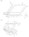
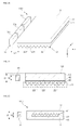
- FIG. 1 is a perspective view of a lighting device according to an embodiment of the present invention.
- FIG. 2 is a partially enlarged cross-sectional view showing a part of the lighting device of FIG. 1 .
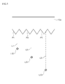
- FIG. 3 is another partially enlarged view of the lighting device of FIG. 1 .
- a lighting device 100 includes: a light guide portion 10a; a three-dimensional effect forming portion 21; and a light source portion 30.
- the light guide portion 10a has a plate or film form and guides light of the inside from one side to the other side.
- the light guide portion 10a is provided as a transparent substrate.
- the light guide portion 10a may be provided as a transparent member in a plate or film form having a haze of 2% or less. In this case, the light guide portion 10a has transparency in which an object of the other surface can be observed from one surface by clairvoyance.
- the light guide portion 10a may be made of glass, resin or the like.
- a thermoplastic polymer, a photocurable polymer or the like may be used as a material of the light guide portion 10a. More specifically, the material of the light guide portion 10a may be polycarbonate, polymethylmethacrylate, polystyrene, polyethylene terephthalate or the like.
- the light guide portion 10a may have a thickness t1 of about 0.1 mm or more and about 10.0 mm or less.
- a thickness t1 of the light guide portion 10a is smaller than 0.1 mm, it is difficult to produce a height of a light emitting surface of an LED element of the light source portion 30 to be smaller than 100 ⁇ m or heavy production costs are consumed.
- the thickness T1 of the light guide portion 10a is larger than 10.0 mm, a thickness and a weight of the device may be increased and material costs may be also increased.
- the light guide portion 10a may have a thickness t1 of about 100 ⁇ m or more and about 250 ⁇ m or less.
- the light guide portion 10a may have flexibility for enabling the light guide portion to be appropriately wound on a roll device.
- the thickness t1 of the light guide portion 10a may be in the range of about 250 ⁇ m or more and about 10.0 mm or less. In this case, since it is difficult to wind the light guide portion 10a on a roll device, the light guide portion may have a plate form and may be applied to an application product in such a form.
- the three-dimensional effect forming portion 21 is configured to include multiple patterns 22 provided by removing a part of one surface of the light guide portion 10a.
- the multiple patterns 22 have respective inclined surfaces 221 inclined with respect to a first surface of the light guide portion 10a or a second surface 102 opposite to the first surface and are configured to include respective concave portions or respective convex portions which are sequentially arranged in a predetermined direction (x-direction) of the first surface.
- sequential arrangement directions of the multiple patterns 22 are designed in desired directions, the optical path of the incident beam passing along the three-dimensional effect forming portion 21 may be guided into a desired path (the first path), and the optical width and the luminous intensity may be limited to a desired form.
- the light source portion 30 creates an incident beam that is reflected inside the light guide portion 10a and moves by irradiating light on a side of the light guide portion 10a.
- the light source portion 30 may include at least one LED (Light Emitting Diode) light source.
- the LED light source may be provided in an LED string form or an LED package form having a single LED element or multiple LED elements. In the case where the LED light source is used, the light source of the light source portion 30 may have a light emitting surface with a predetermined area according to each LED chip size.
- the light source may be intended to include the plural forms.
- the light source portion 30 may be arranged to be separated from one side of the light guide portion 10a by a predetermined distance w0.
- a separation space therebetween may be filled with a transparent material such as resin or the like.
- the light source portion 30 may be configured to be closely attached to one side of the light guide portion 10a without a separation space or may be configured to be buried in an inner side of the light guide portion 10a.
- the light emitting surface of the light source may be arranged to face the side of the light source portion 10a and may have a circular shape, an elliptical shape, a triangular shape, a quadrangular shape, a pentagonal shape or a polygonal shape.
- a height of the light emitting surface may be defined as a maximum length in a thickness direction of the light guide portion 10a
- a width of the light emitting surface may be defined as a maximum length in a direction that crosses at right angles to a thickness direction in the side of the light guide portion 10a and is parallel to the light emitting surface.
- a height t2 of the light source portion 30 in the thickness direction of the light guide portion 10a is smaller than the thickness t1 of the light source portion 10a. This is intended for the light guide portion 10a so as to appropriately function as a member for receiving and guiding the incident beam when light emitted from the light emitting surface of the light source portion 30 is irradiated.
- the light (the incident beam) traveling inside the light guide portion 10a is guided in a first surface direction toward which the first surface of the light guide portion 10a looks and a second surface direction toward which the second surface 102 looks by reflection and refraction generated from the inclined surfaces 221 of the multiple patterns 22 of the three-dimensional effect forming portion 21, and thanks to the guided light, the lighting device 100 implements a line shaped beam of a first path which crosses at right angles to respective pattern extension directions of the multiple patterns.
- light, which meets with the inclined surface 221 of each pattern 22 of the three-dimensional effect forming portion 21, is refracted or reflected according to each incidence angle. That is, when the incidence angle is smaller than a critical angle ⁇ c, the light passing along the light guide portion 10a penetrates the patterns 22 and is refracted according to a difference in a refractive index. Also, the light passing along the light guide portion 10a is reflected from the inclined surfaces 221 of the patterns 22 when the incidence angle is more than the critical angle ⁇ c.
- Equation 1 A relation between the reflective index and the critical angle is represented by following Equations 1 and 2.
- n1 is a reflective index of air
- n2 is a reflective index of a medium (light guide portion)
- the critical angle may be represented by following Equation 3.
- the lighting device implements optical images having desired shapes and guided in a first surface direction toward which the first surface of the light guide portion 10a looks and in a second surface direction toward which the second surface 102 looks, by refraction and reflection of an incident beam from the multiple patterns 22 of the three-dimensional effect forming portion.
- the lighting device For appropriate refraction and reflection of the incident beam passing along the light guide portion 10a, the lighting device according to the present embodiment is designed so that the inclined surface of each of the patterns can have a predetermined surface roughness.
- the inclined surface 221 may be a mirror-like finishing surface.
- the inclined surface 221 may be a precision processing surface.
- a center line average roughness or an arithmetic mean roughness Ra may be about 0.02 or less, and a maximum height roughness Rmax may be about 0.3.
- the surface roughness of the inclined surface may be a ten point median height Rz of less than 0.8.
- the unit of roughness may be ⁇ m, and a standard length may be 0.25 mm.
- the surface roughness of the inclined surface is intended to secure a reflectance of the inclined surface in a range beyond a predetermined value.
- the surface roughness shows a larger surface roughness than the value described above, it is difficult to properly implement a line shaped beam due to the scattering of light or light beyond a fixed amount returning from the inclined surface to the light source.
- a line shaped beam or a three-dimensional effect beam of a specific optical path may be implemented by controlling a refraction and reflection ability of the inclined surfaces 221 of the multiple patterns 22 through a pattern design for the patterns 22 of the three-dimensional effect forming portion 21.
- the light passing along the multiple patterns 22 of the three-dimensional effect forming portion 21 may be guided to a specific optical path and may be limited to an optical width by refraction and reflection from the inclined surfaces of the patterns according to the pattern design.
- the specific optical path refers to a movement path of light guided in the direction crossing each of the pattern extension directions of the multiple patterns 22.
- the specific optical path includes the first path of light traveling along the direction in which the multiple patterns are sequentially arranged.
- the principle of generation of the optical path is based on the Fermat's principle that 'a ray of light passing along the three-dimensional effect forming portion 21, namely, a ray of light passing along a medium travels along a movement path that can be traversed in the least time.'
- the specific optical width may be limited in a desired shape through a pattern design for controlling pattern conditions, such as a between adjacent two main patterns and the like.
- the specific optical path and the specific optical width may be implemented to extend to the extent of a first length while having a fixed width according to a pattern design, may be implemented to extend to the extent of a second length shorter than the first length while having an optical width which reduces gradually, or may be implemented to be similar to the first length or to be shorter or longer than the first length while having an optical width which increases gradually.
- the optical path, the optical width and luminous intensity of the incident beam passing along the light guide portion 10a can be controlled through the pattern design, and accordingly, line shaped beams, three-dimensional effect beams or line shape beams with a three-dimensional effect can be implemented.
- the line shaped beam, the three-dimensional effect beam or the line shaped beam with the three-dimensional effect will be described in greater detail with reference to FIG. 3 as follows.
- a first pattern P1, a second pattern P2 and a third pattern P3 are selected from the multiple patterns of the three-dimensional effect forming portion.
- the first to third patterns P1, P2, P3 are sequentially arranged at a position which is gradually further away from the light source.
- the first to third patterns P1, P2, P3 may be sequentially arranged patterns or patterns in which another pattern is arranged between two adjacent patterns.
- a second optical path from the light source to the second pattern is longer than a first optical path with respect to the first pattern, and is smaller than a third optical path with respect to the third pattern.
- a second distance L2 from a second dummy light source LS2 of the light source resulting from the inclined surface of the second pattern to the inclined surface of the second pattern is longer than a first distance L1 from a first dummy light source LS1 of the light source resulting from the inclined surface of the first pattern to the inclined surface of the first pattern, and is shorter than a third distance L3 from a third dummy light source LS3 of the light source resulting from the inclined surface of the third pattern to the inclined surface of the third pattern.
- the multiple patterns of the three-dimensional effect forming portion serve as indirect light sources which are located far away from a predetermined standard point or an observing point as each distance (corresponding to L1, L2, L3) from the light source portion 30 as viewed from the outside of the light guide portion 10a is gradually increased by refraction and reflection of each of the inclined surfaces.
- specific parts of the optical path of the multiple patterns serves as indirect light sources, and at this time, the indirect light sources are sequentially arranged along the optical path, and as each distance from the light sources is gradually increased, the indirect light sources are provided as dummy light sources LS1, LS2, LS3 in which the intensity of light is reduced by being located far away from the standard point.
- the three-dimensional effect beam may refer to an optical image having a sense of distance or a perceptional depth, which is configured such that a kind of line-shape beam concentrated into a predetermined optical path (the first path) by a pattern design gradually enters the light guide portion 10a, namely, from the first surface of the light guide portion 10a toward the second surface of the light guide portion 10a, as viewed from the first surface direction or the second surface direction.
- the three-dimensional effect beam may be one example of a line shaped beam and may be another name for a specific optical image of the line shaped beam.
- the multiple patterns of the three-dimensional effect forming portion are operated as indirect light sources in which as a distance from the light source is gradually increased by the inclined surface of each of the multiple pattern, optical paths become longer in regular sequence and brightness becomes lower, so that the lighting device may create a three-dimensional effect beam having a sense of distance and a perceptional depth in the thickness direction of the light guide portion 10a.
- the multiple patterns 22 are provided by removing a part of the first surface of the light guide portion 10a, but the present invention is not limited thereto. That is, according to some embodiments, the multiple patterns 22 may be provided by a separate pattern layer bonded to the first surface or the second surface of the light guide portion 10a.
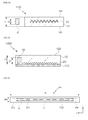
- FIG. 4 is a partially enlarged view of the lighting device of FIG. 1 .
- FIG. 4 may correspond to a partially enlarged view of the multiple patterns as viewed to face the three-dimensional effect forming portion 21 of the light guide portion 10a of FIG. 1 in a state of being placed on a plane.
- a part (a first incident beam) of beams emitted from the light source LS is implemented as a line shaped beam B1 traveling along the first path which crosses at right angles to respective pattern extension directions x1, x2, x3, x4 of the multiple patterns P1, P2, P3, P4.
- the y-direction becomes a direction of the first path.
- the multiple patterns P1, P2, P3, P4 guide a second incident beam in a direction other than the first path by refraction and reflection generated from the inclined surfaces.
- the second incident beam may be a beam (hereinafter referred to as 'an ambient beam') that meets with the inclined surfaces by roughly traveling in an inclination direction between a +y direction and a +x direction, and a +y direction and a -x direction on a plan defined by the pattern extension directions and the y-direction, and is refracted or is regularly reflected by the inclined surfaces.
- 'an ambient beam' a beam that meets with the inclined surfaces by roughly traveling in an inclination direction between a +y direction and a +x direction, and a +y direction and a -x direction on a plan defined by the pattern extension directions and the y-direction, and is refracted or is regularly reflected by the inclined surfaces.
- the inclination direction may be defined as, for example, a direction toward a first quadrant and a fourth quadrant of both sides of the line-shape beam B1 in the first path that travels from the light source LS to a +y axis on an x-y plane.
- the x-y plane may correspond to the first surface or the second surface of the light guide portion 10.
- each of the pattern extension directions x1, x2, x3, x4 of the multiple patterns may be a direction in which a specific straight line parallel to the first surface of the light guide portion 10a extends from each inclined surface of the multiple patterns or a direction in which a specific tangent line in contact with a curved line of each inclined surface extends.
- the respective pattern extension directions x1, x2, x3, x4 may be parallel to the first surface of the light guide portion 10a.
- the light passing along the multiple patterns is expressed as a line shaped beam in a straight line form that starts from the pattern P1 which first meets with the incident beam of the light source LS and travels to a specific optical path (the first path) which crosses at right angles to the pattern extension directions of the multiple patterns P2, P3, P4. It may be defined that a length of the line shaped beam is larger than a width of the line shaped beam and an optical width of the line shaped beam is less than a width of the light emitting surface of the light source of the light source portion.
- the light passing along the multiple patterns may be expressed as a line shaped beam in a curved line form in which the beam is bent to a side in which a distance between the adjacent patterns reduces gradually (see FIG. 6 ).
- a distance Lp (corresponding to a pitch or average distance) between two adjacent patterns may range from about 10 ⁇ m to about 500 ⁇ m.
- This distance Lp is based on a minimum distance and a maximum distance for implementing a line shaped beam or a three-dimensional effect beam, and when the distance is beyond the range, it may be difficult to implement the line shaped beam or the three-dimensional effect beam.
- the second incident beam since the second incident beam is dispersed on the respective inclined surfaces of the patterns of the three-dimensional effect forming portion in a relatively wide range, as viewed from an arbitrary standard point on a straight line which crosses the x-y plane, or an observing point, the second incident beam becomes an ambient beam B2, B3 passing along a peripheral portion or a dark space of the periphery of the line shaped beam that is clearly distinguished due to relatively low brightness compared to a line shaped beam portion (hereinafter referred to as 'a bright portion') resulting from the first an incident beam.
- 'a bright portion' a line shaped beam portion
- the lighting device may implement a line shaped beam by limiting and guiding a part of the incident beam from the light source to the first path, and the lighting device may distribute the rest of the incident beam to the ambient beam passing along the dark space of the periphery of the line shaped beam.
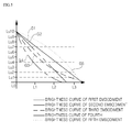
- FIG. 5 is a graph showing a brightness change generated in a first path of the lighting device of FIG. 1 .
- the multiple patterns sequentially arranged from the light source are divided into the patterns of three sections, and reviewing brightness resulting from reflection and refraction of the patterns in the respective areas, each of the multiple patterns shows brightness in different ranges according to each distance L1, L2, L3 from the light source.
- a second brightness of the second patterns is lower than a first brightness of the first patterns and is higher than a third brightness of the third patterns.
- a second distance L2 between the light source and the specific second pattern farthest away from the light source among the second patterns is longer than a first distance L1 between the light source and the specific first pattern farthest away from the light source among the first patterns and is shorter than a third distance L3 between the light source and the specific third pattern farthest away from the light source among the third patterns.
- the specific first main pattern positioned at the first distance L1 from the light source may have a brightness of about level 8 Lu8, level 7 Lu7, level 6 Lu6, level 5 Lu5 or level 4 Lu4 according to different pattern designs of the first to fifth embodiment.
- the specific second main pattern positioned at the second distance L2 from the light source may have a brightness of about level 6 Lu6, level 4 Lu4, level 2 Lu2, or level 1 Lu1 according to pattern designs.
- the specific third main pattern positioned at the third distance L3 from the light source may have a brightness of about level 2 Lu2, level 1 Lu1, or level 0 (no brightness).
- the multiple patterns may implement line shaped beams in which an incident beam is refracted and reflected from each inclined surface, and thus luminous intensity reduces as an optical path increases gradually in the first path.
- specific parts of the multiple patterns of the first path function as sequentially arranged indirect light sources in which a sense of distance or a perceptional depth increases and luminous intensity reduces as a distance from the light source increases gradually.
- the first pattern, the second pattern and the third pattern serve as indirect light sources having brightness values of about level 7, level 4 and level 1, respectively.
- the multiple patterns may implement line shaped three-dimensional effect beams having a sense of increased distance from the multiple patterns, and luminous intensity which is substantially regularly reduced.
- the multiple patterns may be designed in a fixed pitch.
- the first pattern, the second pattern and the third pattern serve as indirect light sources having respective brightness values of about level 6, level 3, and level 0.
- the multiple patterns may implement three-dimensional effect beams having an increased perceptional depth in the thickness direction of the light guide portion from the multiple patterns and the intensity of light which is regularly rapidly reduced as a distance from the light sources increases gradually.
- the multiple patterns may be designed such that as a distance from the light sources increases gradually, a pitch reduces or a pattern density per a unit length increases at a fixed rate.
- the first pattern, the second pattern and the third pattern serve as indirect light sources having respective brightness values of about level 5, level 2, and level 1.
- the multiple patterns may implement three-dimensional effect beams in which a brightness reduction rate between the first area L0-L1 and the second area L1-12 is larger than a brightness reduction rate between the second area L1-L2 and the third area L2-L3 as a distance from the light source increases gradually.
- the multiple patterns may be designed in a fixed pitch which is narrower than the pitch of the first embodiment, or may be provided such that a pitch is gradually increased according to an increase in a distance from the light source while being designed in a fixed pitch which is narrower than the pitch of the first embodiment.
- the first pattern, the second pattern and the third pattern serve as indirect light sources having respective brightness values of about level 4, level 1, and level 0.
- the multiple patterns may implement three-dimensional effect beams in which brightness is further rapidly reduced relatively compared to the case of the third embodiment.
- the multiple patterns may be designed in a fixed pitch narrower than the pitch of the third embodiment, or may be provided such that a pitch is gradually reduced according to an increase in a distance from the light source while being designed in a fixed pitch narrower than the pitch of the third embodiment.
- the first pattern, the second pattern and the third pattern serve as indirect light sources having respective brightness values of about level 8, level 6, and level 2.
- the multiple patterns may implement three-dimensional effect beams in which a brightness reduction rate between the first area L0-L1 and the second area L1-12 is smaller than a brightness reduction rate between the second area L1-L2 and the third area L2-L3 as a distance from the light source increases gradually.
- the multiple patterns may be designed in a fixed pitch which is wider than the pitch of the first embodiment, or may be provided such that a pitch is gradually reduced according to an increase in the distance from the light source while being designed in a fixed pitch which is wider than the pitch of the first embodiment.
- the effect of the reduction in brightness and the effect of the indirect light sources of the multiple patterns resulting from a difference in the distance from the light sources namely, a difference in optical paths, a line shaped beam, a three-dimensional effect beam or a line shaped beam with a three-dimensional effect can be implemented.
- FIG. 6 is a partially enlarged plan view of a three-dimensional effect forming portion which can be applied to the lighting device of FIG. 1 .
- a lighting device 100A is configured to include the light guide portion 10, the three-dimensional effect forming portion provided on one surface of the light guide portion 10 and the light source portion (see reference numeral 30 of FIG. 1 ).
- the three-dimensional effect forming portion is configured to include the multiple patterns provided in a structure in which pattern arrangement directions cross each other from the first surface of the light guide portion 10.
- the multiple patterns include a first pattern C1, a second pattern C2, a third main C3, an n-second pattern Cn-2, an n-first pattern, and an n th pattern Cn in order of the location nearest to the light source.
- n is a natural number of 6 or more.
- the multiple patterns are arranged to extend in directions which are not parallel to each other. That is, with regard to the respective pattern extension directions of the multiple patterns, virtual extension lines thereof may meet at one point of intersection C.
- the multiple patterns may implement a line shaped beam BL1 of the first path (optical path) which is bent with a curvature to a side in which the pattern extension directions cross each other, namely, a side in the which an intersecting point C is present.
- the light travels along a direction meeting at right angles to each of the pattern extension direction of the multiple main patterns according to the Fermat's principle that 'a ray of light traveling in a medium travels along a movement path that can be traversed in the least time.
- the lighting device of the present embodiment expresses a line shaped beam BL2 traveling along another optical path instead of the line shaped beam BL1 traveling along the first path. This is because the position of the first path meeting at right angles to the pattern extension directions of the multiple patterns is moved to a direction opposite to the movement direction of the standard point according to a change of the standard point.
- the lighting device of the present embodiment may implement the line shape beams having various optical images (a straight line form, a curved line form or a combination form thereof) expressed by traveling along the pattern extension directions of the multiple patterns according to the position of the standard point or the observing point through a pattern design of the three-dimensional effect forming portion.
- various optical images a straight line form, a curved line form or a combination form thereof
- FIG. 7 is a view showing patterns of the three-dimensional effect forming portion of the lighting device of FIG. 1 .
- the respective patterns 22 of the three-dimensional effect forming portion 21 may be provided so as to have a pattern structure in a triangular cross section form.
- each of the inclined surfaces 221 has a fixed inclination angle in the extension direction (y-direction) of the first surface or the pattern arrangement surface (see reference numeral 101 of FIG. 8 ).
- each of the inclined surfaces 221 is provided to be bent to the extent of a fixed inclination angle ⁇ with respect to the direction (z-direction) meeting at right angles to the pattern arrangement surface.
- the inclination angle ⁇ is larger than about 5° and smaller than about 85°.
- the inclination angle ⁇ may be further limited in consideration of a refractive index of the light guide portion, but the inclination angle may be basically designed in the range of about 5° to 85° in consideration of reflection and refraction beyond a fixed level from the inclined surfaces 221.
- an inclination angle of the inclined surface 221 on one side of the respective patterns 22 may be larger than 33.7° and smaller than 50.3°, or may be larger than 49.7° and smaller than 56.3° according to a standard direction (z-direction or y-direction).
- the light guide portion or the multiple patterns may be made of a material having a high refractive index.
- n value a refractive index
- n 1.80 ⁇ 2.50
- the inclination angle of the inclined surface 221 of each pattern 22 may be larger than 23.6° and smaller than about 56.3°, or may be larger than 33.7° and smaller than 66.4° according to each refractive index of the multiple patterns.
- the multiple patterns may be coated with at least one functional layer having a high refractive index for refractive index adjustment.
- An inclination angle according to the refractive index may be represented by following Equation 4 according to the Snell's law.
- Equation 4 sin ⁇ 1 is a traveling angle or an incidence angle of light shown in a first medium of a first refractive index n1, and sin ⁇ 2 is an incidence angle or a traveling angle of light shown in a second medium of a second refractive index n2.
- each of the multiple main patterns in the present embodiment may be provided to have an inclination angle ⁇ ranging from about 5° to about 85° as an inclination angle which enables an incident beam to be reflected or refracted appropriately.
- a rate of a width w to a height h may be limited to a fixed rate for convenience of a production process.
- a width of a bottom surface may correspond to a pitch.
- the width w of each of the patterns 22 may be provided to be equal to or smaller than the height h. Also, when the patterns are designed so that the line shaped beam with the three-dimensional effect can express a relatively long image, the width w of each of the patterns 22 may be provided to be larger than the height h.
- a rate (h/w) of a width (or a diameter) to a height of each of the multiple patterns 22 may be about 1/2 or less.
- an inclination angle ⁇ of the inclined surface of each of the patterns 22 may be about 60°or less.
- optical images of the line shaped beam, the three-dimensional effect beam or the like intended to be expressed by the lighting device may be efficiently controlled.
- the width w between two adjacent patterns in the three-dimensional effect forming portion 21 may be 10 to 500 ⁇ m.
- This width w may refer to an average distance among the multiple main patterns of the first path, and may be regularly or variously selected according to each pattern design or each desired shape of optical images.
- the multiple patterns may be configured to be concavely inserted into an inner side of the light guide portion in the pattern arrangement surface or the first surface of the light guide portion.
- each inclined surface of the patterns as the case described above has an inclination angle with respect to the pattern arrangement surface or the z-direction, and when a rate (h/w) of a width to a height of each of the patterns is designed to be about 1 or less, it may be easy to produce the patterns compared to the case in which a rate (h/w) of the width to the height of each of the patterns is 1 or more.
- FIG. 8 is a view showing another embodiment for the patterns of the three-dimensional effect forming portion shown in FIG. 7 ;
- the multiple patterns 22 may be provided so as to have a pattern structure having a semicircular cross section or a semielliptical cross section.
- Each of the patterns 22 has an inclined surface inclined at a predetermined angle in a thickness direction (z-direction) of the light guide portion or a direction (y-direction) to which the first surface or a pattern arrangement surface 101 extends.
- Each of the patterns 22 may have a symmetrical form based on a center line (not drawn) in the z-direction, but is not limited thereto.
- the inclined surface of each of the patterns 22 may have a structure in which an inclination angle is changed according to each position of the inclined surface due to the semicircular structure of the patterns. That is, since the inclined surface of each of the patterns 22 is a surface in contact with an arbitrary point on a circular arc, a tangent line in contact with an arbitrary point on each of the patterns 22 or a surface in contact with the arbitrary point may be placed at a fixed inclination angle ⁇ in the direction (the z-direction) meeting at right angles to the pattern arrangement surface 101.
- the inclination angle ⁇ may be larger than 0° and smaller than 90° according to each position of a circular cross section which the beam BL hits.
- the three-dimensional effect forming portion 21 of the present embodiment may include a spaced portion 102 provided between two adjacent patterns. That is, when the multiple patterns include a first pattern Cm-1, a second pattern Cm and a third pattern Cm+1 (wherein, m is a natural number of 2 or more), the three-dimensional effect forming portion 21 may include pattern separation portions 12 provided between the first pattern Cm-1 and the second pattern Cm, and between the second pattern Cm and the third pattern Cm+1.
- Each of the pattern separation portions 102 may be a part of the first surface 101 positioned between two adjacent patterns as a part of the first surface 101 of the light guide portion in which concave patterns are not formed. Also, the pattern separation portion 102 may be provided for convenience of the manufacturing process as a gap between two adjacent patterns. The pattern separation portion 102 may be omitted according to a manufacturing process or a pattern design of specific implementation.
- a width w1 of the pattern separation portion 102 is smaller than a width w of the pattern 22.
- the width w1 of the pattern separation portion 102 is may be about 1/5 or less or several ⁇ m or less of the width w of the pattern 22.
- FIG. 9 is a view showing still another embodiment for the patterns of the three-dimensional effect forming portion shown in FIG. 7 .
- the multiple patterns 22 may be provided to have a pattern structure having a polygonal section form.
- Each of the inclined surfaces 221 of the patterns 22 may have a broken-line graph form.
- each of the inclined surfaces 221 of the patterns 22 is provided so as to have multiple inclination angles ⁇ 1, ⁇ 2 according to the number of segments of the broken-line graph in the direction (z-direction) crossing at right angles to the first surface or the pattern arrangement surface 101.
- the second inclination angle ⁇ 2 may be larger than the first inclination angle ⁇ 1.
- the first and second inclination angles ⁇ 1, ⁇ 2 may be designed within the range which is larger than about 5° and smaller than about 85° according to a position where the beam BL hits.
- the three-dimensional effect forming portion 21 may be configured to further include the pattern separation portion 102 provided between two adjacent patterns.
- a width w1 of the pattern separation portion 102 is smaller than the width w of each of patterns in order to naturally implement a line shaped beam or a three-dimensional effect beam via the three-dimensional effect forming portion 21.
- the width w1 of the pattern separation portion 102 may be designed to be narrow maximally or may be designed so that the pattern separation portion 102 can be omitted.
- the pattern separation portion 102 is designed to have the width w1 of several ⁇ m or less.
- the three-dimensional effect forming portion 21 may have an interrupted surface 223 parallel to the pattern arrangement surface 113 of the respective patterns.
- the interrupted surface 223 is a part which does not function to enable light to be substantially emitted to the outside through the reflection or refraction of incident beam.
- a width w2 of the interrupted surface 223 may be appropriately designed in a range of several ⁇ m or less in order to implement a line shaped beam having a desired shape.
- FIG. 10 is a perspective view of a lighting device according to another embodiment of the present invention.
- FIG. 11 is a cross-sectional view of the lighting device of FIG. 10 .
- a lighting device 100A is configured to include: the light guide portion 10; the three-dimensional effect forming portion 21 provided on the first surface of the light guide portion 10; and the light source portion 30.
- a lighting device 100A includes: the light guide portion 10; the three-dimensional effect forming portion 21 provided on the first surface of the light guide portion 10; and the light source portion 30.
- the lighting device 100A of the present embodiment may be substantially identical to the lighting device 100 explained with reference to FIGS. 1 to 3 except for the fact that the three-dimensional effect forming portion 21 is provided by bonding a separate pattern layer 20 rather than being provided in a form in which a part of one surface of the light guide portion is removed.
- the pattern layer 20 is made of a material identical or similar to that of the light guide portion 10.
- the pattern layer 20 may be provided with a transparent member having the multiple patterns.
- a resin material such as a thermosetting polymer, a photocurable polymer and the like may be used as the material of the pattern layer 20.
- the material of the pattern layer 20 may be polycarbonate, polymethylmethacrylate, polystyrene, polyethylene terephthalate, and the like.
- the pattern layer 20 may be bonded to the first surface of the light guide portion 10 using a separate adhesive material.
- an adhesive layer 40 is disposed between the light guide portion 10 and the pattern layer.
- An optical transparent adhesive, an adhesive and the like may be used as the adhesive material of the adhesive layer 40.
- the adhesive material such as epoxy resin and the like may be used.
- the adhesive layer 40 may be implemented using PEA (Phenoxyethyl Acrylate) which is a high refractive material for adjustment of a refractive index.
- the adhesive layer 40 may be made of a fluorinate polymer, a fluorinate monomer and the like.
- the pattern layer 20 may be directly bonded to the first surface of the light guide portion 10 without using a separate adhesive material.
- the pattern layer 20 has a heat reaction type adhesive property such as heat sealable property and heat welding and the like.
- the light source portion 30 may be identical to the light source portion of the lighting device of FIG. 1 .
- the light source portion 30 of the present embodiment is configured to include multiple light sources 30a, 30b, 30c which are separated from each other by a predetermined distance.
- the light source portion 30 may irradiate light in directions parallel to each other or different directions in different areas of the light guide portion 10 or may irradiate light in opposite directions facing each other. That is, when multiple line shaped beams may be implemented using the patterns of multiple groups arranged in different arrangement directions in different areas of the light guide portion 10, and the multiple light sources, the lighting device 100A of the present embodiment may implement multiple line shaped beams of different optical paths.
- FIG. 12 is a cross-sectional view of a lighting device according to still another embodiment of the present invention.
- a lighting device 100B is configured to include: the light source portion 30; the light guide portion 10; and the three-dimensional effect forming portion 21 buried in the light guide portion.
- the three-dimensional effect forming portion 21 may be implemented by arranging the pattern layer 20 having the multiple patterns on one surface thereof inside the light guide portion 20.
- the light source portion 30 may be substantially identical to any one of the light source portions of the lighting devices previously described with reference to FIGS. 1 to 11 .
- a thickness t1 of the light guide portion 10 is longer than a height of the light source portion 30. More specifically, the thickness t1 of the light guide portion 10 is larger than a height of the light emitting surface of the light source.
- the pattern layer 20 may be the pattern layer previously described with reference to FIGS. 10 and 11 .
- the pattern layer 20 is formed by disposing the pattern layer 20 on a first resin layer provided in a predetermined height for forming the light guide portion 10 and covering an upper part of the first resin layer, on which the pattern layer 20 is disposed, with a second resin layer.
- the multiple patterns of the three-dimensional effect forming portion 21 When the multiple patterns of the three-dimensional effect forming portion 21 are disposed closer to the first surface 101 than the second surface 102 of the light guide portion 10, the multiple patterns may express line shape beams or three-dimensional effect beams by reflection and refraction the most of light traveling inside the light guide portion 10.
- FIG. 13 is a cross-sectional view of a lighting device according to still another embodiment of the present invention.
- FIG. 13 is a plan view of a lighting device according to still another embodiment of the present invention.
- a lighting device 100C is configured to include: the light source portion 30; the light guide portion 10; and the three-dimensional effect forming portion 21 buried in the light guide portion.
- the three-dimensional effect forming portion 21 may be implemented by arranging the pattern layer, which is bent several times in a zigzag form for forming the multiple patterns, inside the light guide portion 10.
- the lighting device 100C of the present embodiment is substantially identical to the lighting device 100B previously described with reference to FIG. 12 except for the fact that the pattern layer 20 is formed in the zigzag form, and accordingly, the detailed description thereof is omitted in order to avoid overlapping.
- FIG. 14 is a cross-sectional view of a lighting device according to still another embodiment of the present invention.
- a lighting device 100D is configured to include: the light guide portion 10; the three-dimensional effect forming portion 21 disposed on one surface of the light guide portion 10; the light source portion 30; and a support member 110.
- the three-dimensional effect forming portion 21 may be disposed between the light guide portion 10 and the support member 110 and may be implemented by the pattern layer 20 having the multiple patterns on one surface thereof.
- the light source portion 30 and the three-dimensional effect forming portion 21 are disposed on one surface of the support member 110, and on the one surface of the support member 110, the light source portion and the three-dimensional effect forming portion are buried by the light guide portion 10.
- a part buried by the light guide portion 10 may be a light source.
- the lighting device 100D of the present embodiment is substantially identical to the lighting device 100B or 100C previously described with reference to FIG. 11 or 12 , except for the fact that the support member 110 is laminated on one surface of the light guide portion 10, and at least one part of the light source portion 30 is buried by the light guide portion 10, and accordingly, the detailed description thereof is omitted for avoiding overlapping.
- the support member 110 may be provided using a transparent substrate.
- the transparent substrate may be made of the same material as that of the light guide portion 10.
- the support member 110 has a thinner thickness than the thickness t1 of the light guide portion 10, but is not limited thereto.
- the support member 110 may have a thicker thickness than the thickness of the light guide portion 10 according to some embodiments.
- the support member 110 may be made of an opaque material according to some embodiments. If any device, product or place enables the pattern layer 20 and the light source portion 30 to be disposed on one surface, and an upper part of a structure, in which the pattern layer 20 and the light source portion 30 are disposed, to be covered by the light guide portion 10, the device, product or place may be used as the opaque material.
- the support member 110 may be at least one part of a housing, a wall inside or outside a building, or one surface of a specific product or an instrument.
- the support member 110 may be implemented by using at least one part of a desktop computer, a monitor frame, a desk, a chair, a portable terminal (smart phone, smart pad or the like), a cap, clothes, shoes, a bag, an accessory, indoor or outdoor interior components and the like.
- FIG. 15 is a plane view of a lighting device according to still another embodiment of the present invention.
- a lighting device 200 is configured to include the light guide portion 10, the pattern layer 20, and the light source portion.
- the lighting device 200 has a predetermined length LH and width WH in a plane.
- the length LH and the width WH may be formed similar or identical to a length or a diameter of a 20W fluorescent lamp or a 40W fluorescent lamp.
- the light guide portion 10 and the pattern layer 20 may form a single optical member.
- the pattern layer 20 includes the multiple patterns that extend from one surface in the x-direction and are sequentially arranged in the y-direction.
- the multiple patterns serve as a three-dimensional effect forming portion.
- the light guide portion 10 may be provided to bury or surround the pattern layer 20.
- the light guide portion 10 and the pattern layer 20 may be identical to the light guide portion 10 and the pattern layer 20 of the embodiment previously described with reference to FIG. 14 .
- the light source portion is configured to include a first light source 30a and a second light source 30b arranged at both ends in a length direction of the light guide portion 10.
- the first light source 30a and the second light source 30b may be provided with one among various existing light sources such as an incandescent lamp, a halogen lamp, a discharge lamp and the like or may be provided using indirect light sources such as a guide member for guiding or reflecting natural light generated from the sun.
- the first light source 30a and the second light source 30b may be provided to include LED (Light Emitting Diode) elements according to some embodiments.
- the light source portion may include a printed circuit board in which the first light sources 30a, the second light source 30b and a drive circuit supplying power to these light sources are installed.
- the first light source 30a and the second light source 30b irradiate light from both ends in the length direction of the light guide portion 10 to a central part.
- the lighting device 200 may express an incident beam from each of the two light sources 30a, 30b as respective line shaped beams GL1, GL2 which start from the both ends in the length direction of the light guide portion to extend in a direction facing the central part and disappear from the central part.
- the present embodiment in different areas of the light guide portion, when a beam in roughly a hemispherical shape is irradiated on the basis of the light source (or a light emitting surface of the light source), by controlling the light source through a pattern design, line shaped beams extending in opposite directions, or line shaped beams extending in directions having an angle of more than 90° and less than 180° in the opposite directions, namely, directions crossing each other, may be implemented. Also, according to some embodiments, by controlling the incident beam of the light source through a pattern design, line shaped beams extending in the same direction or line shaped beams extending in directions crossing each other in the same direction may be implemented (see FIG. 17 ).
- the lighting device 200 may further include a support member or a housing.
- the support member may be substantially identical the support member 110 of the lighting device 100D previously explained with reference to FIG. 14 .
- FIG. 16 is a plane view of a lighting device according to still another embodiment of the present invention.
- a lighting device 300 is configured to include: the light guide portion; the three-dimensional effect forming portion 21; the light source portion 30 and the support member 310.
- the light guide portion may be substantially identical to the light guide portion 10a of the lighting device of FIG. 1 or the light guide portion 10 of the lighting device of each of FIGS. 10 to 15 .
- the three-dimensional effect forming portion 21 may be provided inside the light guide portion or on the first surface or the second surface of the light guide portion. Also, the three-dimensional effect forming portion 21 may be provided so that the multiple patterns of the first area R1 arranged at one side of the light guide portion 10 can integrally continuously extend to the multiple patterns of the twelfth area R12 arranged at the other side of the light guide portion 10 via the multiple patterns of the second to eleventh areas R2 to R11 arranged at the center of the light guide portion. At this time, the respective patterns of the three-dimensional effect forming portion 21 may have a bent portion at a boundary part between two adjacent areas.
- the three-dimensional effect forming portion 21 of the present embodiment may be substantially identical to any one of the three-dimensional effect forming portions of the lighting devices previously explained with reference to FIGS. 1 to 15 , except for the fact that the three dimensional forming portion includes the multiple patterns sequentially arranged in the different areas R1 to R12, respectively of the light guide portion 10.
- the light source portion 30 includes twelve light sources for irradiating light to the respective patterns of the multiple groups of the three-dimensional effect forming portion 21 provided in each of different areas R1, R2, R3, R4, R5, R6, R7, R8, R9, R10, R11 and R12 of the light guide portion 10.
- the respective light sources are LED light sources.
- Each of the light sources is an LED package including two LED elements and is provided so as to emit two beams via the respective LED elements.
- the respective light sources may be LED light sources.
- each of the light sources may be an LED package including LED elements and may be provided to emit two beams via the respective LED elements.
- the first light source and the second light source may be arranged to irradiate the light in directions parallel to each other in the same direction or in directions crossing each other in the same direction.
- the first light source and the second light source may be arranged to irradiate the light in a single straight line direction or in directions parallel to each other in opposite directions, or to irradiate the light in different directions having an angle of more than 90° and less than 180° between the first light source and the second light source.
- the support member 310 supports the light guide portion or the light source portion 30.
- the support member 310 may be substantially identical to the support member 110 of the lighting device 100D previously described with reference to FIG. 14 , except for the fact that the support member has an increased size or is provided to support the multiple light sources.
- FIG. 17 is a plan view showing an operational state of the lighting device of FIG. 16 .
- FIG. 18 is an operational state view of the lighting device of FIG. 16 .
- an incident beam of each of the light sources is irradiated from edges of both sides in a width direction of the light guide portion or the support member 310 to a central part A0, and is converted into a line shaped beam traveling to the first path D1, D2 and the like having a predetermined optical width via the patterns of the respective areas of the light guide portion.
- the optical width of the line shape beam may be less than a width of the light emitting surface of the light sources irradiating the light to the patterns, and a length of the line shaped beam may be larger than the optical width.
- the light of a white LED lamp of about 10W may be implemented as a three-dimensional effect beam or a line shaped beam with a three-dimensional effect in which the intensity of light of the light sources becomes largely weak or disappears at roughly the central part A0 in a width direction of the support member 310.
- the incident beam passing along the light guide portion or the three-dimensional effect forming portion may be expressed by the sequentially arranged patterns as a three-dimensional effect beam in which the intensity of light reduces rapidly and disappears at a very relatively short distance (for example, about 100 to 200 mm) .
- the very short distance corresponds to a short distance beyond '1/(hundreds to thousands of times compared to a distance (for example, several meters to tens of meters) in which light passing along a transparent substrate is naturally reduced and disappears when the light is irradiated to the transparent substrate (corresponding to the base substrate) of a comparative example in which main patterns are not provided.
- each of the light sources of the lighting device irradiates two beams by using the LED package having two LED elements as the light sources, but the present invention is not limited to such a configuration.
- Each of the light sources may irradiate one beam by using the LED package having one LED element as the light sources.
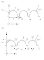
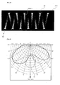
- FIG. 19 is a brightness graph of the light device of FIG. 18 .
- the graph of the present embodiment results from measuring brightness by a brightness measuring instrument in a front central part of the lighting device of FIG. 18 .
- a first brightness (about Lu5) in the central area A0 of the front of the light emitting surface of the light source of the lighting device is relatively largely small compared to a second brightness (about Lu7 to about Lu12) in the other areas of the front of the light emitting surface.
- the intensity of light in the central area A0 of the light emitting surface of the lighting device can be really predicted to be near to 0.
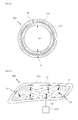
- FIG. 20 is a cross-sectional view a lighting device according to still another embodiment of the present invention.
- a lighting device 400 is configured to include: the light guide portion 10a; the three-dimensional effect forming portion 21; the light source portion 30; and a support member 410.
- the light guide portion 10a and the three-dimensional effect forming portion 21 may be substantially identical to any one of the light guide portions and the three-dimensional effect forming portions of the embodiments previously described with reference to FIGS. 1 to 9 .
- the light guide portion 10a may have a thickness of about 25 to 250 ⁇ m or less.
- the thickness of the light guide portion 10 is smaller than 25 ⁇ m, it may be difficult to produce the light guide portion and durability may be largely reduced.
- the thickness of the light guide portion 10 is larger than 250 ⁇ m, flexibility is reduced, so that it may be difficult to install the light guide portion at the support member 410 have a predetermined curvature R2.
- the light source portion 30 has a thickness similar to or smaller than the thickness of the light guide portion 10 and is disposed to irradiate light on one side of the light guide portion 10.
- the light source portion 30 may be provided as an LED package including one or two or more LED elements.
- the support member 410 may be a housing having a predetermined curvature such as 1/R and the like, a wall inside or outside a building having a bent portion, or one surface of a product.
- the support member 410 has a hollow type cylindrical shape having a predetermined diameter 2R.
- the support member 410 may be implemented using devices or products without being specially limited if the devices or products enable the light guide portion 10 on the sheet and the three-dimensional effect forming portion 21 to be disposed on one side of the light source portion 30 to which light is irradiated. Furthermore, the support member 410 may be implemented using a circular or hollow cap, clothing, shoes, a bag, an accessory, indoor and outdoor interior components and the like to which the light guide portion 10 of the sheet phase may be attached.
- the light guide portion and the three-dimensional effect forming portion are disposed in an application product, an article or a building having a curvature so that illumination of various optical designs may be implemented by line shaped beams or line shaped beams with a three-dimensional effect.
- FIG. 21 is a plan view of a lighting device according to still another embodiment of the present invention.
- a lighting device 500 is configured to include: the light guide portion 10, the three-dimensional effect forming portion, the light source portion 30 and an outer lens 510.
- the light source of the light source portion 30 may be operated by power supplied from a battery 520 of a car.
- the light guide portion 10 may be substantially identical to the light guide portions of the lighting devices previously described with reference to FIGS. 1 to 20 , except for the light guide portion has a streamlined shape as viewed from a plane and has a curvature from a fixed portion in a thickness direction.
- the three-dimensional effect forming portion is configured to include multiple patterns provided in different areas of the light guide portion 10. Such a configuration of the three-dimensional effect forming portion is substantially similar or identical to that of the three-dimensional effect forming portion of the lighting device 300 previously described with reference to FIG. 16 , and accordingly, the detailed description thereof is omitted for avoiding overlapping.
- the light source portion 30 includes multiple light sources arranged at an edge of one surface along a streamlined shape of the light guide portion 10.
- the configuration of the other light sources of the light source portions 30 may be substantially identical to that of the light sources of the light source portion for the lighting device previously described with reference to FIGS. 1 to 20 .
- the light guide portion 10 and the three-dimensional effect forming portion are arranged on one surface of an outer lens 510.
- the light guide portion 10 may be bonded to one surface of the outer lens 510 or may be arranged to be separated from the one surface of the outer lens by a predetermined distance.
- the light source portion 30 may be disposed on the one surface of the outer lens 510 or on the other surface corresponding to an opposite surface of the one surface.
- the light sources of the light source portion 30 may be buried in the light guide portion 10.
- the outer lens 510 refers to a lens-shaped cover disposed on an outer surface of the lighting device such as a light device for a vehicle (a headlight, a rear light and the like), an outdoor lighting device and the like.
- the outer lens 510 may be provided on one surface, in which the light guide portion 10 or the three-dimensional effect forming portion is disposed, so as to have a curvature leading to a curved surface of a vehicle body.
- the outer lens 510 may be made of a transparent plastic material, for example, engineering plastic and the like.
- the lighting device 500 of the present embodiment may be usefully applied compared to the existing lamps for vehicles.
- the lighting device 500 of the present embodiment is not limited to a lighting device for vehicles, and may be applied to a curve portion or a bent portion inside or outside an object for illustration installation, such as a building, equipment, furniture and the like, as a flexible lighting device in a film form.
- the outer lens 510 may be a transparent support member or a housing for supporting the light guide portion, a combination of the light guide portion and the three-dimensional effect forming portion, or the light source portion 30.
- some embodiments of the present invention may provide the lighting devices capable of implementing optical images having desired shapes using a line shaped beam by controlling an optical path, an optical width and a change in brightness through a pattern design to create the line shaped beam.
- According to some embodiments of the present invention may provide the lighting devices capable of implementing line shaped beam images having desired shapes by controlling an optical path, an optical width and luminous intensity through a pattern design.
- According to some embodiments of the present invention may provide the lighting devices capable of implementing line shaped beam images having desired shapes by a pattern design and a combination of light guide structures.
Landscapes
- Engineering & Computer Science (AREA)
- Physics & Mathematics (AREA)
- General Engineering & Computer Science (AREA)
- Optics & Photonics (AREA)
- General Physics & Mathematics (AREA)
- Mechanical Engineering (AREA)
- Microelectronics & Electronic Packaging (AREA)
- Planar Illumination Modules (AREA)
Applications Claiming Priority (1)
| Application Number | Priority Date | Filing Date | Title |
|---|---|---|---|
| KR1020130164888A KR102147938B1 (ko) | 2013-12-27 | 2013-12-27 | 조명장치 |
Publications (3)
| Publication Number | Publication Date |
|---|---|
| EP2889657A2 true EP2889657A2 (de) | 2015-07-01 |
| EP2889657A3 EP2889657A3 (de) | 2015-07-22 |
| EP2889657B1 EP2889657B1 (de) | 2020-09-02 |
Family
ID=52394830
Family Applications (1)
| Application Number | Title | Priority Date | Filing Date |
|---|---|---|---|
| EP14200279.9A Active EP2889657B1 (de) | 2013-12-27 | 2014-12-24 | Beleuchtungsvorrichtung mit linienförmigem Strahl |
Country Status (4)
| Country | Link |
|---|---|
| US (1) | US9952376B2 (de) |
| EP (1) | EP2889657B1 (de) |
| KR (1) | KR102147938B1 (de) |
| CN (1) | CN104748072B (de) |
Families Citing this family (9)
| Publication number | Priority date | Publication date | Assignee | Title |
|---|---|---|---|---|
| KR20150076553A (ko) * | 2013-12-27 | 2015-07-07 | 엘지이노텍 주식회사 | 선형광을 이용하는 조명장치 |
| GB201601974D0 (en) * | 2016-02-03 | 2016-03-16 | Heraeus Noblelight Ltd | Pulsed light system |
| DE102016118884A1 (de) | 2016-10-05 | 2018-04-05 | Temicon Gmbh | Lichtumlenkvorrichtung, Beleuchtungseinrichtung und Verwendung |
| DE102017003036A1 (de) * | 2017-03-29 | 2018-10-04 | Singulus Technologies Ag | Leuchtkörper |
| US10914447B2 (en) * | 2018-12-28 | 2021-02-09 | Continental Automotive Systems, Inc. | Optical wave guided daytime running lights |
| KR102855691B1 (ko) * | 2019-12-09 | 2025-09-05 | 현대모비스 주식회사 | 3차원 패턴 구현이 가능한 차량 실내용 감성 조명 장치 |
| CN110906270A (zh) * | 2019-12-24 | 2020-03-24 | 东风雷诺汽车有限公司 | 一种能够在内部实现立体悬浮发光图案的车灯 |
| KR102224832B1 (ko) * | 2020-07-07 | 2021-03-08 | 코오롱글로텍주식회사 | 면조명 장치 및 이의 제조방법 |
| CN112298027B (zh) | 2020-11-03 | 2022-05-10 | 上海延锋金桥汽车饰件系统有限公司 | 一种车辆内饰件 |
Family Cites Families (25)
| Publication number | Priority date | Publication date | Assignee | Title |
|---|---|---|---|---|
| US5269977A (en) * | 1990-01-12 | 1993-12-14 | Nissen Kagakukogyo K.K. | Method of manufacturing a foam transparent organic glass plate |
| EP0544332B1 (de) * | 1991-11-28 | 1997-01-29 | Enplas Corporation | Flächenartige Lichtquelle |
| JP3187280B2 (ja) * | 1995-05-23 | 2001-07-11 | シャープ株式会社 | 面照明装置 |
| US7108414B2 (en) * | 1995-06-27 | 2006-09-19 | Solid State Opto Limited | Light emitting panel assemblies |
| JP4122161B2 (ja) | 2002-02-04 | 2008-07-23 | 日本電産コパル株式会社 | 面発光装置 |
| KR100472468B1 (ko) * | 2002-08-07 | 2005-03-10 | 삼성전자주식회사 | 광가이드 및 이를 적용한 화상형성장치 |
| JP4273930B2 (ja) * | 2003-10-31 | 2009-06-03 | ソニー株式会社 | 導光板及びバックライト装置 |
| JP4431952B2 (ja) * | 2003-11-10 | 2010-03-17 | オムロン株式会社 | 面光源装置及び当該装置を用いた機器 |
| JPWO2007123202A1 (ja) * | 2006-04-20 | 2009-09-03 | 株式会社フジクラ | 表示装置およびその製造方法、パターン表示方法、ならびにブラインド装置およびブラインド方法 |
| KR100819253B1 (ko) * | 2006-07-19 | 2008-04-02 | 삼성전자주식회사 | 휴대 단말기용 백라이트 유닛 |
| CN101523256B (zh) * | 2006-10-09 | 2013-01-02 | 皇家飞利浦电子股份有限公司 | 灯以及灯的使用 |
| US20090091912A1 (en) * | 2007-10-09 | 2009-04-09 | Hsin-Chin Lee | Light-guiding key structure with lateral light-guiding function |
| CN101514801A (zh) * | 2008-02-22 | 2009-08-26 | 富士迈半导体精密工业(上海)有限公司 | 照明装置 |
| TWM347535U (en) * | 2008-06-17 | 2008-12-21 | yun-heng Xu | Structural improvement of light guide plate |
| WO2010003273A1 (zh) * | 2008-07-08 | 2010-01-14 | 海立尔股份有限公司 | 可挠式背光模块结构 |
| CN101932875B (zh) * | 2008-08-26 | 2013-01-09 | 潘定国 | 等截面三角形定向棱镜圆形反光板及由其制成的圆板灯 |
| US8591052B2 (en) * | 2008-10-27 | 2013-11-26 | 3M Innovative Properties Company | Semispecular hollow backlight with gradient extraction |
| EP2390556A4 (de) * | 2009-03-06 | 2013-08-28 | Sharp Kk | Planare beleuchtungsvorrichtung und damit versehene anzeigevorrichtung |
| JP2012528361A (ja) * | 2009-05-29 | 2012-11-12 | クォルコム・メムズ・テクノロジーズ・インコーポレーテッド | 反射ディスプレイ用の照明デバイス |
| CN101907266A (zh) * | 2009-06-05 | 2010-12-08 | 旭丽电子(广州)有限公司 | 具有防水功能的可挠式光束导引模块 |
| US20120268687A1 (en) * | 2009-12-15 | 2012-10-25 | Sharp Kabushiki Kaisha | Optical laminate, illuminating device, liquid crystal display device, and method for manufacturing optical laminate |
| DE102010019051A1 (de) * | 2010-05-03 | 2011-11-03 | Osram Opto Semiconductors Gmbh | Flächenlichtleiter und Beleuchtungseinrichtung |
| TW201305668A (zh) * | 2011-04-15 | 2013-02-01 | Semiconductor Energy Lab | 導光元件,背光單元,及顯示裝置 |
| JP2012252249A (ja) * | 2011-06-06 | 2012-12-20 | Sony Corp | 光源デバイスおよび表示装置 |
| KR20130044136A (ko) * | 2012-07-16 | 2013-05-02 | 유태근 | 에지형 엘이디 조명기기 |
-
2013
- 2013-12-27 KR KR1020130164888A patent/KR102147938B1/ko active Active
-
2014
- 2014-12-24 EP EP14200279.9A patent/EP2889657B1/de active Active
- 2014-12-24 US US14/582,569 patent/US9952376B2/en active Active
- 2014-12-26 CN CN201410829361.7A patent/CN104748072B/zh active Active
Non-Patent Citations (1)
| Title |
|---|
| None |
Also Published As
| Publication number | Publication date |
|---|---|
| CN104748072B (zh) | 2019-10-08 |
| EP2889657A3 (de) | 2015-07-22 |
| US9952376B2 (en) | 2018-04-24 |
| KR102147938B1 (ko) | 2020-08-25 |
| KR20150076550A (ko) | 2015-07-07 |
| US20150185401A1 (en) | 2015-07-02 |
| EP2889657B1 (de) | 2020-09-02 |
| CN104748072A (zh) | 2015-07-01 |
Similar Documents
| Publication | Publication Date | Title |
|---|---|---|
| EP2889657B1 (de) | Beleuchtungsvorrichtung mit linienförmigem Strahl | |
| US10935199B2 (en) | Lighting device having non-planar diffuser with array of 3D elements | |
| EP2889532B1 (de) | Beleuchtungsvorrichtung zum Erzeugen mehrerer linienförmiger Strahlen | |
| US10125948B2 (en) | Optical member and lighting device using the same | |
| EP3104211B1 (de) | Optisches element und beleuchtungsvorrichtung damit | |
| EP2889530A1 (de) | Beleuchtungsvorrichtung mit linienförmigem Strahl | |
| US10767837B2 (en) | Optical member and lighting device using the same | |
| KR20150108215A (ko) | 측면 반사를 이용하는 조명 부재 및 이를 이용하는 조명 장치 |
Legal Events
| Date | Code | Title | Description |
|---|---|---|---|
| PUAL | Search report despatched |
Free format text: ORIGINAL CODE: 0009013 |
|
| PUAI | Public reference made under article 153(3) epc to a published international application that has entered the european phase |
Free format text: ORIGINAL CODE: 0009012 |
|
| 17P | Request for examination filed |
Effective date: 20150116 |
|
| AK | Designated contracting states |
Kind code of ref document: A2 Designated state(s): AL AT BE BG CH CY CZ DE DK EE ES FI FR GB GR HR HU IE IS IT LI LT LU LV MC MK MT NL NO PL PT RO RS SE SI SK SM TR |
|
| AX | Request for extension of the european patent |
Extension state: BA ME |
|
| AK | Designated contracting states |
Kind code of ref document: A3 Designated state(s): AL AT BE BG CH CY CZ DE DK EE ES FI FR GB GR HR HU IE IS IT LI LT LU LV MC MK MT NL NO PL PT RO RS SE SI SK SM TR |
|
| AX | Request for extension of the european patent |
Extension state: BA ME |
|
| RIC1 | Information provided on ipc code assigned before grant |
Ipc: F21V 8/00 20060101ALI20150616BHEP Ipc: G02B 6/00 20060101AFI20150616BHEP |
|
| RBV | Designated contracting states (corrected) |
Designated state(s): AL AT BE BG CH CY CZ DE DK EE ES FI FR GB GR HR HU IE IS IT LI LT LU LV MC MK MT NL NO PL PT RO RS SE SI SK SM TR |
|
| RAP1 | Party data changed (applicant data changed or rights of an application transferred) |
Owner name: LG INNOTEK CO., LTD. |
|
| STAA | Information on the status of an ep patent application or granted ep patent |
Free format text: STATUS: EXAMINATION IS IN PROGRESS |
|
| 17Q | First examination report despatched |
Effective date: 20180928 |
|
| GRAP | Despatch of communication of intention to grant a patent |
Free format text: ORIGINAL CODE: EPIDOSNIGR1 |
|
| STAA | Information on the status of an ep patent application or granted ep patent |
Free format text: STATUS: GRANT OF PATENT IS INTENDED |
|
| INTG | Intention to grant announced |
Effective date: 20200325 |
|
| GRAS | Grant fee paid |
Free format text: ORIGINAL CODE: EPIDOSNIGR3 |
|
| GRAA | (expected) grant |
Free format text: ORIGINAL CODE: 0009210 |
|
| STAA | Information on the status of an ep patent application or granted ep patent |
Free format text: STATUS: THE PATENT HAS BEEN GRANTED |
|
| AK | Designated contracting states |
Kind code of ref document: B1 Designated state(s): AL AT BE BG CH CY CZ DE DK EE ES FI FR GB GR HR HU IE IS IT LI LT LU LV MC MK MT NL NO PL PT RO RS SE SI SK SM TR |
|
| REG | Reference to a national code |
Ref country code: GB Ref legal event code: FG4D |
|
| REG | Reference to a national code |
Ref country code: AT Ref legal event code: REF Ref document number: 1309501 Country of ref document: AT Kind code of ref document: T Effective date: 20200915 Ref country code: CH Ref legal event code: EP |
|
| REG | Reference to a national code |
Ref country code: DE Ref legal event code: R096 Ref document number: 602014069626 Country of ref document: DE |
|
| REG | Reference to a national code |
Ref country code: IE Ref legal event code: FG4D |
|
| REG | Reference to a national code |
Ref country code: NL Ref legal event code: FP |
|
| REG | Reference to a national code |
Ref country code: LT Ref legal event code: MG4D |
|
| PG25 | Lapsed in a contracting state [announced via postgrant information from national office to epo] |
Ref country code: GR Free format text: LAPSE BECAUSE OF FAILURE TO SUBMIT A TRANSLATION OF THE DESCRIPTION OR TO PAY THE FEE WITHIN THE PRESCRIBED TIME-LIMIT Effective date: 20201203 Ref country code: NO Free format text: LAPSE BECAUSE OF FAILURE TO SUBMIT A TRANSLATION OF THE DESCRIPTION OR TO PAY THE FEE WITHIN THE PRESCRIBED TIME-LIMIT Effective date: 20201202 Ref country code: BG Free format text: LAPSE BECAUSE OF FAILURE TO SUBMIT A TRANSLATION OF THE DESCRIPTION OR TO PAY THE FEE WITHIN THE PRESCRIBED TIME-LIMIT Effective date: 20201202 Ref country code: FI Free format text: LAPSE BECAUSE OF FAILURE TO SUBMIT A TRANSLATION OF THE DESCRIPTION OR TO PAY THE FEE WITHIN THE PRESCRIBED TIME-LIMIT Effective date: 20200902 Ref country code: LT Free format text: LAPSE BECAUSE OF FAILURE TO SUBMIT A TRANSLATION OF THE DESCRIPTION OR TO PAY THE FEE WITHIN THE PRESCRIBED TIME-LIMIT Effective date: 20200902 Ref country code: HR Free format text: LAPSE BECAUSE OF FAILURE TO SUBMIT A TRANSLATION OF THE DESCRIPTION OR TO PAY THE FEE WITHIN THE PRESCRIBED TIME-LIMIT Effective date: 20200902 Ref country code: SE Free format text: LAPSE BECAUSE OF FAILURE TO SUBMIT A TRANSLATION OF THE DESCRIPTION OR TO PAY THE FEE WITHIN THE PRESCRIBED TIME-LIMIT Effective date: 20200902 |
|
| REG | Reference to a national code |
Ref country code: AT Ref legal event code: MK05 Ref document number: 1309501 Country of ref document: AT Kind code of ref document: T Effective date: 20200902 |
|
| PG25 | Lapsed in a contracting state [announced via postgrant information from national office to epo] |
Ref country code: LV Free format text: LAPSE BECAUSE OF FAILURE TO SUBMIT A TRANSLATION OF THE DESCRIPTION OR TO PAY THE FEE WITHIN THE PRESCRIBED TIME-LIMIT Effective date: 20200902 Ref country code: RS Free format text: LAPSE BECAUSE OF FAILURE TO SUBMIT A TRANSLATION OF THE DESCRIPTION OR TO PAY THE FEE WITHIN THE PRESCRIBED TIME-LIMIT Effective date: 20200902 Ref country code: PL Free format text: LAPSE BECAUSE OF FAILURE TO SUBMIT A TRANSLATION OF THE DESCRIPTION OR TO PAY THE FEE WITHIN THE PRESCRIBED TIME-LIMIT Effective date: 20200902 |
|
| PG25 | Lapsed in a contracting state [announced via postgrant information from national office to epo] |
Ref country code: PT Free format text: LAPSE BECAUSE OF FAILURE TO SUBMIT A TRANSLATION OF THE DESCRIPTION OR TO PAY THE FEE WITHIN THE PRESCRIBED TIME-LIMIT Effective date: 20210104 Ref country code: RO Free format text: LAPSE BECAUSE OF FAILURE TO SUBMIT A TRANSLATION OF THE DESCRIPTION OR TO PAY THE FEE WITHIN THE PRESCRIBED TIME-LIMIT Effective date: 20200902 Ref country code: SM Free format text: LAPSE BECAUSE OF FAILURE TO SUBMIT A TRANSLATION OF THE DESCRIPTION OR TO PAY THE FEE WITHIN THE PRESCRIBED TIME-LIMIT Effective date: 20200902 Ref country code: CZ Free format text: LAPSE BECAUSE OF FAILURE TO SUBMIT A TRANSLATION OF THE DESCRIPTION OR TO PAY THE FEE WITHIN THE PRESCRIBED TIME-LIMIT Effective date: 20200902 Ref country code: EE Free format text: LAPSE BECAUSE OF FAILURE TO SUBMIT A TRANSLATION OF THE DESCRIPTION OR TO PAY THE FEE WITHIN THE PRESCRIBED TIME-LIMIT Effective date: 20200902 |
|
| PG25 | Lapsed in a contracting state [announced via postgrant information from national office to epo] |
Ref country code: IS Free format text: LAPSE BECAUSE OF FAILURE TO SUBMIT A TRANSLATION OF THE DESCRIPTION OR TO PAY THE FEE WITHIN THE PRESCRIBED TIME-LIMIT Effective date: 20210102 Ref country code: ES Free format text: LAPSE BECAUSE OF FAILURE TO SUBMIT A TRANSLATION OF THE DESCRIPTION OR TO PAY THE FEE WITHIN THE PRESCRIBED TIME-LIMIT Effective date: 20200902 Ref country code: AL Free format text: LAPSE BECAUSE OF FAILURE TO SUBMIT A TRANSLATION OF THE DESCRIPTION OR TO PAY THE FEE WITHIN THE PRESCRIBED TIME-LIMIT Effective date: 20200902 Ref country code: AT Free format text: LAPSE BECAUSE OF FAILURE TO SUBMIT A TRANSLATION OF THE DESCRIPTION OR TO PAY THE FEE WITHIN THE PRESCRIBED TIME-LIMIT Effective date: 20200902 |
|
| REG | Reference to a national code |
Ref country code: DE Ref legal event code: R097 Ref document number: 602014069626 Country of ref document: DE |
|
| PG25 | Lapsed in a contracting state [announced via postgrant information from national office to epo] |
Ref country code: SK Free format text: LAPSE BECAUSE OF FAILURE TO SUBMIT A TRANSLATION OF THE DESCRIPTION OR TO PAY THE FEE WITHIN THE PRESCRIBED TIME-LIMIT Effective date: 20200902 |
|
| PLBE | No opposition filed within time limit |
Free format text: ORIGINAL CODE: 0009261 |
|
| STAA | Information on the status of an ep patent application or granted ep patent |
Free format text: STATUS: NO OPPOSITION FILED WITHIN TIME LIMIT |
|
| REG | Reference to a national code |
Ref country code: CH Ref legal event code: PL |
|
| 26N | No opposition filed |
Effective date: 20210603 |
|
| PG25 | Lapsed in a contracting state [announced via postgrant information from national office to epo] |
Ref country code: SI Free format text: LAPSE BECAUSE OF FAILURE TO SUBMIT A TRANSLATION OF THE DESCRIPTION OR TO PAY THE FEE WITHIN THE PRESCRIBED TIME-LIMIT Effective date: 20200902 Ref country code: DK Free format text: LAPSE BECAUSE OF FAILURE TO SUBMIT A TRANSLATION OF THE DESCRIPTION OR TO PAY THE FEE WITHIN THE PRESCRIBED TIME-LIMIT Effective date: 20200902 Ref country code: MC Free format text: LAPSE BECAUSE OF FAILURE TO SUBMIT A TRANSLATION OF THE DESCRIPTION OR TO PAY THE FEE WITHIN THE PRESCRIBED TIME-LIMIT Effective date: 20200902 |
|
| REG | Reference to a national code |
Ref country code: BE Ref legal event code: MM Effective date: 20201231 |
|
| PG25 | Lapsed in a contracting state [announced via postgrant information from national office to epo] |
Ref country code: IE Free format text: LAPSE BECAUSE OF NON-PAYMENT OF DUE FEES Effective date: 20201224 Ref country code: IT Free format text: LAPSE BECAUSE OF FAILURE TO SUBMIT A TRANSLATION OF THE DESCRIPTION OR TO PAY THE FEE WITHIN THE PRESCRIBED TIME-LIMIT Effective date: 20200902 Ref country code: LU Free format text: LAPSE BECAUSE OF NON-PAYMENT OF DUE FEES Effective date: 20201224 Ref country code: FR Free format text: LAPSE BECAUSE OF NON-PAYMENT OF DUE FEES Effective date: 20201231 |
|
| PG25 | Lapsed in a contracting state [announced via postgrant information from national office to epo] |
Ref country code: LI Free format text: LAPSE BECAUSE OF NON-PAYMENT OF DUE FEES Effective date: 20201231 Ref country code: CH Free format text: LAPSE BECAUSE OF NON-PAYMENT OF DUE FEES Effective date: 20201231 |
|
| PG25 | Lapsed in a contracting state [announced via postgrant information from national office to epo] |
Ref country code: TR Free format text: LAPSE BECAUSE OF FAILURE TO SUBMIT A TRANSLATION OF THE DESCRIPTION OR TO PAY THE FEE WITHIN THE PRESCRIBED TIME-LIMIT Effective date: 20200902 Ref country code: MT Free format text: LAPSE BECAUSE OF FAILURE TO SUBMIT A TRANSLATION OF THE DESCRIPTION OR TO PAY THE FEE WITHIN THE PRESCRIBED TIME-LIMIT Effective date: 20200902 Ref country code: CY Free format text: LAPSE BECAUSE OF FAILURE TO SUBMIT A TRANSLATION OF THE DESCRIPTION OR TO PAY THE FEE WITHIN THE PRESCRIBED TIME-LIMIT Effective date: 20200902 |
|
| PG25 | Lapsed in a contracting state [announced via postgrant information from national office to epo] |
Ref country code: MK Free format text: LAPSE BECAUSE OF FAILURE TO SUBMIT A TRANSLATION OF THE DESCRIPTION OR TO PAY THE FEE WITHIN THE PRESCRIBED TIME-LIMIT Effective date: 20200902 |
|
| PG25 | Lapsed in a contracting state [announced via postgrant information from national office to epo] |
Ref country code: BE Free format text: LAPSE BECAUSE OF NON-PAYMENT OF DUE FEES Effective date: 20201231 |
|
| PGFP | Annual fee paid to national office [announced via postgrant information from national office to epo] |
Ref country code: NL Payment date: 20251120 Year of fee payment: 12 |
|
| PGFP | Annual fee paid to national office [announced via postgrant information from national office to epo] |
Ref country code: DE Payment date: 20251120 Year of fee payment: 12 |
|
| PGFP | Annual fee paid to national office [announced via postgrant information from national office to epo] |
Ref country code: GB Payment date: 20251120 Year of fee payment: 12 |