EP2889701A2 - Synchronisierungsmechanismus für Uhrwerk - Google Patents
Synchronisierungsmechanismus für Uhrwerk Download PDFInfo
- Publication number
- EP2889701A2 EP2889701A2 EP14184158.5A EP14184158A EP2889701A2 EP 2889701 A2 EP2889701 A2 EP 2889701A2 EP 14184158 A EP14184158 A EP 14184158A EP 2889701 A2 EP2889701 A2 EP 2889701A2
- Authority
- EP
- European Patent Office
- Prior art keywords
- ring
- axis
- driver
- movement
- annular resonator
- Prior art date
- Legal status (The legal status is an assumption and is not a legal conclusion. Google has not performed a legal analysis and makes no representation as to the accuracy of the status listed.)
- Granted
Links
Images



Classifications
-
- G—PHYSICS
- G04—HOROLOGY
- G04C—ELECTROMECHANICAL CLOCKS OR WATCHES
- G04C3/00—Electromechanical clocks or watches independent of other time-pieces and in which the movement is maintained by electric means
- G04C3/04—Electromechanical clocks or watches independent of other time-pieces and in which the movement is maintained by electric means wherein movement is regulated by a balance
- G04C3/047—Electromechanical clocks or watches independent of other time-pieces and in which the movement is maintained by electric means wherein movement is regulated by a balance using other coupling means, e.g. electrostrictive, magnetostrictive
-
- G—PHYSICS
- G04—HOROLOGY
- G04B—MECHANICALLY-DRIVEN CLOCKS OR WATCHES; MECHANICAL PARTS OF CLOCKS OR WATCHES IN GENERAL; TIME PIECES USING THE POSITION OF THE SUN, MOON OR STARS
- G04B15/00—Escapements
- G04B15/06—Free escapements
- G04B15/08—Lever escapements
-
- G—PHYSICS
- G04—HOROLOGY
- G04B—MECHANICALLY-DRIVEN CLOCKS OR WATCHES; MECHANICAL PARTS OF CLOCKS OR WATCHES IN GENERAL; TIME PIECES USING THE POSITION OF THE SUN, MOON OR STARS
- G04B15/00—Escapements
- G04B15/14—Component parts or constructional details, e.g. construction of the lever or the escape wheel
-
- G—PHYSICS
- G04—HOROLOGY
- G04C—ELECTROMECHANICAL CLOCKS OR WATCHES
- G04C5/00—Electric or magnetic means for converting oscillatory to rotary motion in time-pieces, i.e. electric or magnetic escapements
- G04C5/005—Magnetic or electromagnetic means
Definitions
- the invention relates to a mechanism for synchronizing the speed of rotation of a gear train subjected to a torque in a watch movement.
- the invention also relates to a watch movement comprising, fixed on a plate, energy storage means and an actuating gear of such a mechanism.
- the invention also relates to a timepiece comprising such a movement.
- the invention relates to the field of the regulation of mechanical timepieces, in particular mechanical watches.
- the Swiss lever escapement generally used has a fairly low efficiency (of the order of 35%).
- the invention proposes to create mechanisms which would have a higher performance than the efficiency of the Swiss lever escapement.
- the invention consists of a system for synchronizing a gear driven by a motor spring with a resonator.
- the invention relates to a mechanism for synchronizing the rotational speed of a gear train subjected to a torque in a watch movement, characterized in that said mechanism comprises an annular resonator comprising a ring arranged around an axis, which ring is deformable periodically under the action induced by the movement of a trainer, that includes said mechanism, and which coach is driven, directly or indirectly, by said pair.
- the invention also relates to a watch movement comprising, fixed on a plate, energy storage means and an actuating gear of such a mechanism comprising an annular resonator, with a ring fixed by flexible blades to the platinum, and a trainer driven by the gear, this coach controlling means of displaying the second of the movement.
- the invention also relates to a timepiece comprising such a movement, characterized in that this piece is a watch.
- ring will be called a volume similar to an open torus, unfolding, closed on itself, around an axis. This "ring” is substantially of revolution about this axis, but not necessarily exactly of revolution around this axis.
- a particular type of resonator combines the implementation of different waves.
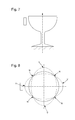
- a so-called "glassglas" laboratory resonator or wine glass in which the tulip of a stemmed glass, the foot of which is held in recess, is subjected to a particular sound excitation.
- the excitation frequency effected by a loudspeaker in the vicinity of the glass
- a resonant frequency of the glass of the order of 800 to 900 Hz
- a signal power of about 100 W we can create in the tulip of the glass a wave network bringing important deformations of this tulip, which seen in plan at the opening of the glass, perpendicular to the axis of the foot, give at a given moment to the edge of the an elliptical shape, as visible on the Figures 7 and 8 , on the latter being spotted the nodes of vibration N and the bellies V.
- This elliptic form is deformable, and the maintenance of the excitation makes evolve this form in ellipse, by modifying its eccentricity, and going up to swap the major axis and the minor axis of the ellipse, passing through the eccentricity position equal to one corresponding to the free form of the edge of the glass. These deformations can go as far as causing the glass to break.
- the excitation source is disposed radially, it is found the presence of four identical vibration bellows, one of which directly opposite the excitation source, the vibration nodes being in directions at 45 ° of the defined axis. by the axis of the glass and the source of excitation.
- This phenomenon is due to a standing wave.
- This standing wave can be seen as the sum of a progressive wave and a regressive wave propagating in both directions along the edge of the glass, in an annular zone, substantially of revolution.
- u x t sin kx + ⁇ t + sin kx - ⁇ t
- the invention proposes to extrapolate such a principle, which is without known industrial application, by exciting a single wave, for example the traveling wave, by acting on a deformable ring.
- This wave can then rotate at the same speed around the edge of the ring as an excitation source, here constituted, without limitation, by a trainer, in particular constituted by a central crank or by a wheel.
- the wave propagates in the material of the ring.
- the wave has the effect of an elastic deformation of the ring (bending).
- the excitation is continuous.
- the passage of the trainer at a point is analogous to a sinus vertex.
- the signal is preferably periodic.
- the effect of the wave related to the presence of the trainer tends to push the ring radially, forcing it to deform elastically.
- the excitation wave is a wave of elastic deformation of the ring, which is a wave approximately transverse, resulting in a substantially radial deformation.
- the object subjected to this or these excitation waves is of preferably substantially annular shape, the ring torus of perfect revolution being a special case.
- This object can be kept in simple embedding as the foot of the glass in the laboratory example described above.
- the figures show variants where recessed blades hold the ring.
- these blades are very flexible relative to the ring, to allow proper operation.
- the invention relates to a mechanism for synchronizing the rotational speed of a clockwork train with a deformable annular resonator, substantially concentric with the axis of the coach, which performs the function usually assigned to the escape wheel in a classic clockwork train.
- this annular resonator is similar to a resonator of the "wineglass" type, as described above.
- the interaction between the trainer and the resonator may be mechanical or non-contact, in particular of the magnetic and / or electrostatic type.
- the invention relates to a mechanism 1 for synchronizing the speed of rotation of a gear train 2 of a watch movement 10 subjected to a torque, in particular from a means of energy storage 3 that this movement comprises. .
- this mechanism 1 comprises an annular resonator 6 comprising a ring 7, which is deformable about an axis A under the effect of an action induced by the movement of a driver 8, that includes the mechanism 1
- This trainer 8 is driven, directly or indirectly, by this pair, and more particularly by said energy storage means 3, in particular from a cylinder via a gear train.
- the speed of the driver 8 defines a speed of propagation of a wave of deformation in the material of the ring 7 all around it.
- the speed of the driver 8 defines a stationary oscillation wave of the ring 7 between repetitive forms corresponding to stationary modes.
- this driver 8 drives a display 4, for example a second display, of the watch movement 10.
- the movement of the coach 8 includes a pivoting movement.
- the movement of the driver 8 is a pivoting movement.
- the driver 8 comprises at least one distal end 800 which extends, relative to the axis A, beyond the smallest diameter that has, in an unstressed free state, the ring 7 with respect to the Axis A. More particularly, at least one distal end 800 locally deforms the ring 7 in the form of a bead 700) protruding radially outwards with respect to the axis A.
- At least one distal end 800 is arranged to cooperate with at least one clearance 71 that comprises, in an unstressed free state, the ring 7 at its inner periphery on the side of the axis A.
- the ring 7 comprises, in an unstressed free state, at its inner periphery on the side of the axis A, at least one bulge 70 facing the axis A constituting the smallest diameter that presents the ring 7 with respect to the axis A.
- the interaction between the driver 8 and the annular resonator 6 is mechanical.
- the driver 8 exerts at least one radial force with respect to the axis A in the centrifugal direction on the ring 7.
- the ring 7 is fixed to a plate 5 that includes said watch movement 10 by a plurality of flexible blades 9, which in a first alternative are more flexible than the ring 7, arranged to hold the ring 7 substantially centered on said axis A, and to restrict the movements of the ring 7 in the same plane P perpendicular to the axis A with limited displacements of the center of inertia of the ring 7 less than one-tenth of the smallest dimension outer ring 7 in said plane P.
- these flexible blades 9 are more rigid than the ring 7.
- annular resonator 6 of the "wineglass” type is synchronized with a driver 8 acting as a crank.
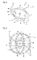
- the figure 2 shows the shape of the resonator at rest, and the Figures 1 and 3 show the extreme states that can take the ring resonator 6 during the evolution of the crank.
- the ring 7 of the annular resonator 6 is fixed to a plate 5 that the watch movement 10 comprises by a plurality of flexible blades 9, more flexible than the ring 7, and which are arranged to hold the ring 7 centered on the axis A, and to restrict the movements of this ring 7 in the same plane P perpendicular to the axis A at very short strokes, especially with strokes less than one-tenth of the smallest outer dimension of the ring 7 in this plane P.
- this smaller dimension is the length of the minor axis of the flatter ellipse corresponding to an extreme deformation of this ring 7.
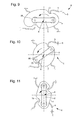
- FIG. 9 to 11 illustrate a similar configuration, but where the flexible blades 9 are attached to areas likely to become nodes of vibration, at 45 ° modulo 90 ° with respect to the horizontal axis of the figures, and wherein the annular resonator is not strictly of revolution in the free state, but comprises two narrowing, as visible in FIG. figure 10 , forcing the trainer to exert on the ring an additional radial force to cross them.
- the interaction between the driver 8 and the annular resonator 6 is of the mechanical type, and the driver 8 induces a radial centrifugal force on the ring 7.
- the interaction between the driver 8 and the annular resonator 6 is achieved by magnetic interaction means 11 comprising magnets and / or magnetic poles.
- the ring 7 comprises a plurality according to a first number of magnets or magnetic poles
- the driver 8 comprises a plurality according to a second number of magnets or magnetic poles, the first number being different from the second number , so that the ring 7 and the driver 8 together constitute a gear reduction mechanism or multiplier. More particularly, the first number differs from the second number by one unit.
- the shape of the magnetic interaction means 11 or magnets defines first zones forming potential ramps and second potential barrier zones, making it possible to locate a pulse between the driver 8 and the annular resonator 6 .
- the interaction between the driver 8 and the annular resonator 6 is performed by electrostatic interaction means comprising electrets or / and electrostatically conductive poles.
- the form of the electrostatic magnetic interaction means 11 or electrets defines first zones forming potential ramps and second potential barrier zones, making it possible to locate a pulse between the driver 8 and the electrodes; the annular resonator 6.
- the coach 8 carries T-shaped magnets 81, which, in certain relative positions of the coach 8 and the ring 7, will arrive in superposition, initially partial then total, with zones of the ring 7, equipped or not with magnetic tracks 71.
- a first branch 82 of the magnet 81 begins to cooperate with the magnetic stripe 71 antagonist, forming a potential ramp, then a transverse bar 83 of the magnet 81 forms a real potential barrier generating a pulse.
- the ring 7 is weighted on its periphery, continuously or periodically, for example by flyweights 75 giving the ring 7 thus equipped the appearance of a vehicle crawler.
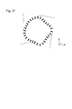
- the Figures 27 to 31 illustrate the advantage these weights bring by lowering the frequency of the first eigen modes.
- the ring 7 is weighted on its periphery, continuously or periodically.
- the ring 7 is ballasted by a plurality of weights 75.
- At least some weights 75 extend externally to the ring 7 relative to the axis A, with a T-shaped profile whose vertical bar is radial with respect to the axis A, and whose bar cross is perpendicular to the axis A and the farthest from it.
- the figure 4 thus illustrates an annular resonator 6 of the "wineglass” type weighted in order to lower the natural frequency, synchronized with a crank.
- the figure 5 illustrates an annular resonator 6 of wineglass type weighted to lower the natural frequency, synchronized magnetically with a wheel.
- magnets as interaction elements between the wheel and the resonator makes it possible to eliminate friction losses, impact noise and losses due to "falls".
- the shape of the magnets can be optimized to obtain a ramp / potential barrier effect for locating the pulse.
- the driver 8 is advantageously a crank inducing a mechanical deformation of the ring 7.
- the driver 8 is a wheel arranged to exert a contactless force on the ring 7.
- the wheel carries a crank arm provided with at least one roller 85 arranged to roll or slide on the inner peripheral surface of the ring 7 on the side of the axis A.
- the ring 7 may have sections and / or varying thicknesses along its periphery.
- the ring 7 has, in an unstressed free state, a polygonal or multi-lobed shape in a plane P orthogonal to the axis A.
- the ring 7 is made of micro-machinable material or silicon and has a rectangular section in any plane passing through said axis A.
- the ring 7 is integral with a plurality of flexible blades 9 connecting with a plate 5 that includes the watch movement 10. More particularly, the ring 7 is integral with the plurality of flexible blades 9 and with the platinum 5.
- the driver 8 is driven by a gearing mechanism or speed multiplier interposed between the energy storage means 3 and the driver 8. More particularly, this gear reduction mechanism or speed multiplier is a coupling mechanism magnetic, as visible on the figure 6 , which illustrates an annular resonator 6 of the "wineglass” type weighted in order to lower the natural frequency, synchronized magnetically with a wheel, via a magnetic multiplier, arranged to have an escape wheel that rotates at a frequency lower than the frequency own of the resonator.
- the driver 8 comprises a first disk having magnetic fields 81 alternating in a first step, and cooperating with a second disk having magnetic fields 82 in a second step, very close, but different from the first step.
- Another variant not illustrated, consists of the combination of a mechanical and magnetic or electrostatic interaction.
- the invention also relates to a clockwork movement 10 comprising, fixed on a plate 5, energy storage means 3 arranged to deliver torque to an actuating gear 2 of such a mechanism 1 comprising an annular resonator 6 , with a ring 7 fixed by flexible blades 9 to the plate 5, and a driver 8 driven by the gear 2, the driver 8 controlling display means 4, including the display of the second, the movement 10.
- the invention also relates to a timepiece 100 comprising such a movement 10. More particularly, this piece 200 is a watch.
- the invention has important advantages: the invention makes it possible to eliminate the jerky movements of a Swiss lever escapement, and hence the losses due to shocks. The exhaust efficiency is substantially increased.
- Such an annular resonator does not have pivots, and therefore does not support the frictional losses of the pivots of a spiral balance.
- crank variants represent purely mechanical synchronization systems, which can not pick up.
- the invention proposes an innovation in the field of the exhaust and the resonator. It has, again, a strong emotional potential because of its visual similarities with a beating heart.
Landscapes
- Physics & Mathematics (AREA)
- General Physics & Mathematics (AREA)
- Electromagnetism (AREA)
- Electric Clocks (AREA)
- Electromechanical Clocks (AREA)
Priority Applications (21)
| Application Number | Priority Date | Filing Date | Title |
|---|---|---|---|
| EP14186652.5A EP2891929B1 (de) | 2013-12-23 | 2014-09-26 | Magnetischer oder elektrostatischer Resonator |
| CN201480070607.5A CN105849651B (zh) | 2013-12-23 | 2014-12-08 | 钟表同步机构 |
| US15/104,135 US9772604B2 (en) | 2013-12-23 | 2014-12-08 | Timepiece synchronization mechanism |
| JP2016540025A JP6196736B2 (ja) | 2013-12-23 | 2014-12-08 | 計時器用同期機構 |
| PCT/EP2014/076936 WO2015096974A2 (fr) | 2013-12-23 | 2014-12-08 | Mecanisme de synchronisation d'horlogerie |
| RU2016130283A RU2629168C1 (ru) | 2013-12-23 | 2014-12-08 | Механизм синхронизации часов |
| PCT/EP2014/076991 WO2015096976A2 (fr) | 2013-12-23 | 2014-12-09 | Resonateur magnetique ou electrostatique |
| CN201480070592.2A CN105849653B (zh) | 2013-12-23 | 2014-12-09 | 磁性和/或静电谐振器 |
| US15/102,389 US9651920B2 (en) | 2013-12-23 | 2014-12-09 | Magnetic and/or electrostatic resonator |
| JP2016541686A JP6166847B2 (ja) | 2013-12-23 | 2014-12-09 | 磁気的及び/又は静電気的な共振器 |
| RU2016130281A RU2624713C1 (ru) | 2013-12-23 | 2014-12-09 | Магнитный и/или электростатический резонатор |
| EP15759451.6A EP3191898B1 (de) | 2014-09-09 | 2015-09-04 | Regler für den betrieb einer mechanischen uhrwerks |
| JP2016563129A JP6220465B2 (ja) | 2014-09-09 | 2015-09-04 | 時計用磁気エスケープ及び時計用ムーブメントの動作を規制するデバイス |
| CN201580052000.9A CN106796411B (zh) | 2014-09-09 | 2015-09-04 | 用于调节机械钟表机芯的运动的装置 |
| PCT/EP2015/070237 WO2016037938A1 (fr) | 2014-09-09 | 2015-09-04 | Echappement magnetique horloger et dispositif regulateur de la marche d'un mouvement horloger |
| JP2017513508A JP6311074B2 (ja) | 2014-09-09 | 2015-09-04 | 機械式計時器用ムーブメントの運動を調整するデバイス |
| PCT/EP2015/070238 WO2016037939A2 (fr) | 2014-09-09 | 2015-09-04 | Dispositif regulateur de la marche d'un mouvement horloger mecanique |
| CN201580023592.1A CN106462109B (zh) | 2014-09-09 | 2015-09-04 | 磁性钟表擒纵机构和用于调节钟表机芯的运行的装置 |
| EP15766420.2A EP3191899B1 (de) | 2014-09-09 | 2015-09-04 | Magnetische ankerhemmung, und gangeinstellvorrichtung eines uhrwerks |
| US15/509,995 US10001753B2 (en) | 2014-09-09 | 2015-09-04 | Device for regulating the motion of a mechanical horological movement |
| US15/308,902 US9891591B2 (en) | 2014-09-09 | 2015-09-04 | Magnetic clock escapement and device for regulating the operation of a clock movement |
Applications Claiming Priority (5)
| Application Number | Priority Date | Filing Date | Title |
|---|---|---|---|
| CH02140/13A CH709019B1 (fr) | 2013-12-23 | 2013-12-23 | Mécanisme d'échappement magnétique ou électrostatique. |
| EP13199427.9A EP2887157B1 (de) | 2013-12-23 | 2013-12-23 | Optimierte uhrhemmung |
| EP14176816 | 2014-07-11 | ||
| CH10572014 | 2014-07-11 | ||
| CH01365/14A CH709056A2 (fr) | 2013-12-23 | 2014-09-09 | Mécanisme de synchronisation d'horlogerie. |
Publications (3)
| Publication Number | Publication Date |
|---|---|
| EP2889701A2 true EP2889701A2 (de) | 2015-07-01 |
| EP2889701A3 EP2889701A3 (de) | 2016-02-17 |
| EP2889701B1 EP2889701B1 (de) | 2017-07-19 |
Family
ID=67393959
Family Applications (1)
| Application Number | Title | Priority Date | Filing Date |
|---|---|---|---|
| EP14184158.5A Active EP2889701B1 (de) | 2013-12-23 | 2014-09-09 | Synchronisierungsmechanismus für Uhrwerk |
Country Status (2)
| Country | Link |
|---|---|
| EP (1) | EP2889701B1 (de) |
| CH (1) | CH709056A2 (de) |
Cited By (5)
| Publication number | Priority date | Publication date | Assignee | Title |
|---|---|---|---|---|
| EP3208667A1 (de) * | 2016-02-18 | 2017-08-23 | The Swatch Group Research and Development Ltd | Magnetisches hemmungsdrehteil eines uhrwerks |
| EP3627236A1 (de) * | 2018-09-21 | 2020-03-25 | Nivarox-FAR S.A. | Elastisches halterungsorgan für die befestigung einer uhrenkomponente auf einem halteelement |
| EP3627235A1 (de) * | 2018-09-21 | 2020-03-25 | Nivarox-FAR S.A. | Elastisches halterungsorgan für die befestigung einer uhrenkomponente auf einem halteelement |
| CN116232520A (zh) * | 2023-03-02 | 2023-06-06 | 深圳市城市公共安全技术研究院有限公司 | 时间同步监测方法、装置、终端设备以及存储介质 |
| CN118597722A (zh) * | 2024-08-07 | 2024-09-06 | 山西亚世智能装备有限公司 | 一种具备检测振动疏堵功能的柔性加载可控流体环保溜槽 |
Families Citing this family (1)
| Publication number | Priority date | Publication date | Assignee | Title |
|---|---|---|---|---|
| EP4202563B1 (de) * | 2021-12-23 | 2025-11-05 | The Swatch Group Research and Development Ltd | Uhrwerksmechanismus mit einem magnetischen getrieberad |
Family Cites Families (5)
| Publication number | Priority date | Publication date | Assignee | Title |
|---|---|---|---|---|
| US2194896A (en) * | 1937-06-21 | 1940-03-26 | Francis C Gromann | Balance wheel structure |
| CH470017A (de) * | 1963-06-24 | 1969-04-30 | Jeco Kk | Elektrische Uhr mit einem stimmgabelartigen, mechanischen Oszillator |
| GB1361672A (en) * | 1971-03-30 | 1974-07-30 | Horstmann Magnetics Ltd | Magnetic rotor drives |
| CH701036A2 (de) * | 2009-05-12 | 2010-11-15 | Peter Gschwind | Mechanische Uhr mit einem platzsparenden Untersetzungsgetriebe für den automatischen Aufzug. |
| EP2544370B1 (de) * | 2011-07-06 | 2020-01-01 | Nxp B.V. | MEMS-Resonator |
-
2014
- 2014-09-09 EP EP14184158.5A patent/EP2889701B1/de active Active
- 2014-09-09 CH CH01365/14A patent/CH709056A2/fr not_active Application Discontinuation
Non-Patent Citations (1)
| Title |
|---|
| None |
Cited By (13)
| Publication number | Priority date | Publication date | Assignee | Title |
|---|---|---|---|---|
| EP3208667A1 (de) * | 2016-02-18 | 2017-08-23 | The Swatch Group Research and Development Ltd | Magnetisches hemmungsdrehteil eines uhrwerks |
| US10095187B2 (en) | 2016-02-18 | 2018-10-09 | The Swatch Group Research And Development Ltd | Magnetic escape wheel set for timepieces |
| CN112740116A (zh) * | 2018-09-21 | 2021-04-30 | 尼瓦洛克斯-法尔股份有限公司 | 用于将钟表构件固定到支承元件的弹性保持件 |
| EP3627235A1 (de) * | 2018-09-21 | 2020-03-25 | Nivarox-FAR S.A. | Elastisches halterungsorgan für die befestigung einer uhrenkomponente auf einem halteelement |
| WO2020057969A1 (fr) * | 2018-09-21 | 2020-03-26 | Nivarox-Far S.A. | Organe de maintien elastique pour la fixation d'un composant d'horlogerie sur un element de support |
| WO2020057919A1 (fr) * | 2018-09-21 | 2020-03-26 | Nivarox-Far S.A. | Organe de maintien elastique pour la fixation d'un composant d'horlogerie sur un element de support |
| EP3627236A1 (de) * | 2018-09-21 | 2020-03-25 | Nivarox-FAR S.A. | Elastisches halterungsorgan für die befestigung einer uhrenkomponente auf einem halteelement |
| CN112740117A (zh) * | 2018-09-21 | 2021-04-30 | 尼瓦洛克斯-法尔股份有限公司 | 用于将钟表构件固定到支承元件的弹性保持件 |
| CN112740116B (zh) * | 2018-09-21 | 2023-04-18 | 尼瓦洛克斯-法尔股份有限公司 | 用于将钟表构件固定到支承元件的弹性保持件 |
| US11906930B2 (en) | 2018-09-21 | 2024-02-20 | Nivarox-Far S.A. | Elastic retaining member for fixing a timepiece component on a support element |
| US12326694B2 (en) | 2018-09-21 | 2025-06-10 | Nivarox-Far S.A. | Elastic retaining member for attaching a timepiece component to a support element |
| CN116232520A (zh) * | 2023-03-02 | 2023-06-06 | 深圳市城市公共安全技术研究院有限公司 | 时间同步监测方法、装置、终端设备以及存储介质 |
| CN118597722A (zh) * | 2024-08-07 | 2024-09-06 | 山西亚世智能装备有限公司 | 一种具备检测振动疏堵功能的柔性加载可控流体环保溜槽 |
Also Published As
| Publication number | Publication date |
|---|---|
| EP2889701A3 (de) | 2016-02-17 |
| CH709056A2 (fr) | 2015-06-30 |
| EP2889701B1 (de) | 2017-07-19 |
Similar Documents
| Publication | Publication Date | Title |
|---|---|---|
| WO2015096974A2 (fr) | Mecanisme de synchronisation d'horlogerie | |
| EP2889701B1 (de) | Synchronisierungsmechanismus für Uhrwerk | |
| EP3087435B1 (de) | Vorrichtung zur steuern der winkelgeschwindigkeit eines räderwerks in einem eine magnetische hemmung unfassnden uhrwerk | |
| EP3234699B1 (de) | Resonator einer uhr mit sich kreuzenden blättern | |
| EP2891930B1 (de) | Vorrichtung zur Regulierung der Winkelgeschwindigkeit einer Triebfeder in einem Uhrwerk, das einen magnetischen Hemmungsmechanismus umfasst | |
| EP2430397B1 (de) | Koppelstruktur für einen resonanzkreisel | |
| EP3130966B1 (de) | Mechanisches uhrwerk, das mit einem bewegungsrückkopplungssysteme ausgestattet ist | |
| EP2887157B1 (de) | Optimierte uhrhemmung | |
| EP3191898B1 (de) | Regler für den betrieb einer mechanischen uhrwerks | |
| EP2911015B1 (de) | Natürliche Hemmung | |
| CH707471B1 (fr) | Système régulateur pour montre mécanique. | |
| EP3602206A1 (de) | Mechanische uhr mit einer bewegung, deren betrieb durch eine korrekturvorrichtung verbessert wird | |
| CH710948A2 (fr) | Mécanisme d'activation magnétique de sonnerie d'horlogerie. | |
| CH715049A2 (fr) | Pièce d'horlogerie comprenant un tourbillon. | |
| WO2000045127A1 (fr) | Gyroscope vibrant | |
| EP3265879B1 (de) | Zeitmessendes uhrwerk mit einem regler mit dreidimensionaler magnetischer resonanz | |
| EP3944027A1 (de) | Tragbares gerät, insbesondere armbanduhr, das mit einer stromquellevorrichtung mit einem elektromechanischen wandler ausgestattet ist | |
| WO2015096976A2 (fr) | Resonateur magnetique ou electrostatique | |
| WO2014180767A1 (fr) | Mouvement horloger à régulateur à résonance tridimensionnelle | |
| EP2891929B1 (de) | Magnetischer oder elektrostatischer Resonator | |
| CH709050A2 (fr) | Résonateur magnétique ou électrostatique. | |
| EP3882713A1 (de) | Uhrwerk, das mit einer uhrhemmung mit einem magnetischen system ausgestattet ist | |
| CH717239A2 (fr) | Mouvement horloger comprenant un échappement muni d'un système magnétique. | |
| FR2614413A1 (fr) | Gyrometre laser, dispositif d'elimination des rotations parasites des miroirs piezoelectriques utilisant les forces d'inertie | |
| HK1228024A1 (en) | Timepiece synchronization mechanism |
Legal Events
| Date | Code | Title | Description |
|---|---|---|---|
| PUAI | Public reference made under article 153(3) epc to a published international application that has entered the european phase |
Free format text: ORIGINAL CODE: 0009012 |
|
| 17P | Request for examination filed |
Effective date: 20140909 |
|
| AK | Designated contracting states |
Kind code of ref document: A2 Designated state(s): AL AT BE BG CH CY CZ DE DK EE ES FI FR GB GR HR HU IE IS IT LI LT LU LV MC MK MT NL NO PL PT RO RS SE SI SK SM TR |
|
| AX | Request for extension of the european patent |
Extension state: BA ME |
|
| RIC1 | Information provided on ipc code assigned before grant |
Ipc: G04B 17/00 20060101ALI20150902BHEP Ipc: G04C 3/10 20060101ALI20150902BHEP Ipc: G04B 15/00 20060101AFI20150902BHEP Ipc: G04B 17/04 20060101ALI20150902BHEP Ipc: G04C 5/00 20060101ALI20150902BHEP Ipc: G04C 3/04 20060101ALI20150902BHEP |
|
| PUAL | Search report despatched |
Free format text: ORIGINAL CODE: 0009013 |
|
| AK | Designated contracting states |
Kind code of ref document: A3 Designated state(s): AL AT BE BG CH CY CZ DE DK EE ES FI FR GB GR HR HU IE IS IT LI LT LU LV MC MK MT NL NO PL PT RO RS SE SI SK SM TR |
|
| AX | Request for extension of the european patent |
Extension state: BA ME |
|
| RIC1 | Information provided on ipc code assigned before grant |
Ipc: G04B 18/00 20060101ALI20160111BHEP Ipc: G04C 3/10 20060101ALI20160111BHEP Ipc: G04B 17/04 20060101ALI20160111BHEP Ipc: G04C 3/04 20060101ALI20160111BHEP Ipc: G04B 17/00 20060101ALI20160111BHEP Ipc: G04C 5/00 20060101ALI20160111BHEP Ipc: G04B 15/00 20060101AFI20160111BHEP |
|
| R17P | Request for examination filed (corrected) |
Effective date: 20160817 |
|
| RBV | Designated contracting states (corrected) |
Designated state(s): AL AT BE BG CH CY CZ DE DK EE ES FI FR GB GR HR HU IE IS IT LI LT LU LV MC MK MT NL NO PL PT RO RS SE SI SK SM TR |
|
| GRAP | Despatch of communication of intention to grant a patent |
Free format text: ORIGINAL CODE: EPIDOSNIGR1 |
|
| INTG | Intention to grant announced |
Effective date: 20170403 |
|
| GRAS | Grant fee paid |
Free format text: ORIGINAL CODE: EPIDOSNIGR3 |
|
| GRAA | (expected) grant |
Free format text: ORIGINAL CODE: 0009210 |
|
| AK | Designated contracting states |
Kind code of ref document: B1 Designated state(s): AL AT BE BG CH CY CZ DE DK EE ES FI FR GB GR HR HU IE IS IT LI LT LU LV MC MK MT NL NO PL PT RO RS SE SI SK SM TR |
|
| REG | Reference to a national code |
Ref country code: GB Ref legal event code: FG4D Free format text: NOT ENGLISH |
|
| REG | Reference to a national code |
Ref country code: CH Ref legal event code: EP Ref country code: CH Ref legal event code: NV Representative=s name: ICB INGENIEURS CONSEILS EN BREVETS SA, CH |
|
| REG | Reference to a national code |
Ref country code: IE Ref legal event code: FG4D Free format text: LANGUAGE OF EP DOCUMENT: FRENCH |
|
| REG | Reference to a national code |
Ref country code: AT Ref legal event code: REF Ref document number: 910955 Country of ref document: AT Kind code of ref document: T Effective date: 20170815 |
|
| REG | Reference to a national code |
Ref country code: DE Ref legal event code: R096 Ref document number: 602014011888 Country of ref document: DE |
|
| REG | Reference to a national code |
Ref country code: FR Ref legal event code: PLFP Year of fee payment: 4 |
|
| REG | Reference to a national code |
Ref country code: NL Ref legal event code: MP Effective date: 20170719 |
|
| REG | Reference to a national code |
Ref country code: LT Ref legal event code: MG4D |
|
| REG | Reference to a national code |
Ref country code: AT Ref legal event code: MK05 Ref document number: 910955 Country of ref document: AT Kind code of ref document: T Effective date: 20170719 |
|
| PG25 | Lapsed in a contracting state [announced via postgrant information from national office to epo] |
Ref country code: FI Free format text: LAPSE BECAUSE OF FAILURE TO SUBMIT A TRANSLATION OF THE DESCRIPTION OR TO PAY THE FEE WITHIN THE PRESCRIBED TIME-LIMIT Effective date: 20170719 Ref country code: HR Free format text: LAPSE BECAUSE OF FAILURE TO SUBMIT A TRANSLATION OF THE DESCRIPTION OR TO PAY THE FEE WITHIN THE PRESCRIBED TIME-LIMIT Effective date: 20170719 Ref country code: LT Free format text: LAPSE BECAUSE OF FAILURE TO SUBMIT A TRANSLATION OF THE DESCRIPTION OR TO PAY THE FEE WITHIN THE PRESCRIBED TIME-LIMIT Effective date: 20170719 Ref country code: SE Free format text: LAPSE BECAUSE OF FAILURE TO SUBMIT A TRANSLATION OF THE DESCRIPTION OR TO PAY THE FEE WITHIN THE PRESCRIBED TIME-LIMIT Effective date: 20170719 Ref country code: NL Free format text: LAPSE BECAUSE OF FAILURE TO SUBMIT A TRANSLATION OF THE DESCRIPTION OR TO PAY THE FEE WITHIN THE PRESCRIBED TIME-LIMIT Effective date: 20170719 Ref country code: AT Free format text: LAPSE BECAUSE OF FAILURE TO SUBMIT A TRANSLATION OF THE DESCRIPTION OR TO PAY THE FEE WITHIN THE PRESCRIBED TIME-LIMIT Effective date: 20170719 Ref country code: NO Free format text: LAPSE BECAUSE OF FAILURE TO SUBMIT A TRANSLATION OF THE DESCRIPTION OR TO PAY THE FEE WITHIN THE PRESCRIBED TIME-LIMIT Effective date: 20171019 |
|
| PG25 | Lapsed in a contracting state [announced via postgrant information from national office to epo] |
Ref country code: LV Free format text: LAPSE BECAUSE OF FAILURE TO SUBMIT A TRANSLATION OF THE DESCRIPTION OR TO PAY THE FEE WITHIN THE PRESCRIBED TIME-LIMIT Effective date: 20170719 Ref country code: ES Free format text: LAPSE BECAUSE OF FAILURE TO SUBMIT A TRANSLATION OF THE DESCRIPTION OR TO PAY THE FEE WITHIN THE PRESCRIBED TIME-LIMIT Effective date: 20170719 Ref country code: PL Free format text: LAPSE BECAUSE OF FAILURE TO SUBMIT A TRANSLATION OF THE DESCRIPTION OR TO PAY THE FEE WITHIN THE PRESCRIBED TIME-LIMIT Effective date: 20170719 Ref country code: BG Free format text: LAPSE BECAUSE OF FAILURE TO SUBMIT A TRANSLATION OF THE DESCRIPTION OR TO PAY THE FEE WITHIN THE PRESCRIBED TIME-LIMIT Effective date: 20171019 Ref country code: IS Free format text: LAPSE BECAUSE OF FAILURE TO SUBMIT A TRANSLATION OF THE DESCRIPTION OR TO PAY THE FEE WITHIN THE PRESCRIBED TIME-LIMIT Effective date: 20171119 Ref country code: RS Free format text: LAPSE BECAUSE OF FAILURE TO SUBMIT A TRANSLATION OF THE DESCRIPTION OR TO PAY THE FEE WITHIN THE PRESCRIBED TIME-LIMIT Effective date: 20170719 Ref country code: GR Free format text: LAPSE BECAUSE OF FAILURE TO SUBMIT A TRANSLATION OF THE DESCRIPTION OR TO PAY THE FEE WITHIN THE PRESCRIBED TIME-LIMIT Effective date: 20171020 |
|
| REG | Reference to a national code |
Ref country code: DE Ref legal event code: R097 Ref document number: 602014011888 Country of ref document: DE |
|
| PG25 | Lapsed in a contracting state [announced via postgrant information from national office to epo] |
Ref country code: DK Free format text: LAPSE BECAUSE OF FAILURE TO SUBMIT A TRANSLATION OF THE DESCRIPTION OR TO PAY THE FEE WITHIN THE PRESCRIBED TIME-LIMIT Effective date: 20170719 Ref country code: CZ Free format text: LAPSE BECAUSE OF FAILURE TO SUBMIT A TRANSLATION OF THE DESCRIPTION OR TO PAY THE FEE WITHIN THE PRESCRIBED TIME-LIMIT Effective date: 20170719 Ref country code: RO Free format text: LAPSE BECAUSE OF FAILURE TO SUBMIT A TRANSLATION OF THE DESCRIPTION OR TO PAY THE FEE WITHIN THE PRESCRIBED TIME-LIMIT Effective date: 20170719 |
|
| PLBE | No opposition filed within time limit |
Free format text: ORIGINAL CODE: 0009261 |
|
| STAA | Information on the status of an ep patent application or granted ep patent |
Free format text: STATUS: NO OPPOSITION FILED WITHIN TIME LIMIT |
|
| PG25 | Lapsed in a contracting state [announced via postgrant information from national office to epo] |
Ref country code: SM Free format text: LAPSE BECAUSE OF FAILURE TO SUBMIT A TRANSLATION OF THE DESCRIPTION OR TO PAY THE FEE WITHIN THE PRESCRIBED TIME-LIMIT Effective date: 20170719 Ref country code: SK Free format text: LAPSE BECAUSE OF FAILURE TO SUBMIT A TRANSLATION OF THE DESCRIPTION OR TO PAY THE FEE WITHIN THE PRESCRIBED TIME-LIMIT Effective date: 20170719 Ref country code: EE Free format text: LAPSE BECAUSE OF FAILURE TO SUBMIT A TRANSLATION OF THE DESCRIPTION OR TO PAY THE FEE WITHIN THE PRESCRIBED TIME-LIMIT Effective date: 20170719 Ref country code: MC Free format text: LAPSE BECAUSE OF FAILURE TO SUBMIT A TRANSLATION OF THE DESCRIPTION OR TO PAY THE FEE WITHIN THE PRESCRIBED TIME-LIMIT Effective date: 20170719 Ref country code: IT Free format text: LAPSE BECAUSE OF FAILURE TO SUBMIT A TRANSLATION OF THE DESCRIPTION OR TO PAY THE FEE WITHIN THE PRESCRIBED TIME-LIMIT Effective date: 20170719 |
|
| 26N | No opposition filed |
Effective date: 20180420 |
|
| REG | Reference to a national code |
Ref country code: IE Ref legal event code: MM4A |
|
| REG | Reference to a national code |
Ref country code: BE Ref legal event code: MM Effective date: 20170930 |
|
| PG25 | Lapsed in a contracting state [announced via postgrant information from national office to epo] |
Ref country code: LU Free format text: LAPSE BECAUSE OF NON-PAYMENT OF DUE FEES Effective date: 20170909 |
|
| PG25 | Lapsed in a contracting state [announced via postgrant information from national office to epo] |
Ref country code: IE Free format text: LAPSE BECAUSE OF NON-PAYMENT OF DUE FEES Effective date: 20170909 |
|
| REG | Reference to a national code |
Ref country code: FR Ref legal event code: PLFP Year of fee payment: 5 |
|
| PG25 | Lapsed in a contracting state [announced via postgrant information from national office to epo] |
Ref country code: SI Free format text: LAPSE BECAUSE OF FAILURE TO SUBMIT A TRANSLATION OF THE DESCRIPTION OR TO PAY THE FEE WITHIN THE PRESCRIBED TIME-LIMIT Effective date: 20170719 Ref country code: BE Free format text: LAPSE BECAUSE OF NON-PAYMENT OF DUE FEES Effective date: 20170930 |
|
| PG25 | Lapsed in a contracting state [announced via postgrant information from national office to epo] |
Ref country code: MT Free format text: LAPSE BECAUSE OF FAILURE TO SUBMIT A TRANSLATION OF THE DESCRIPTION OR TO PAY THE FEE WITHIN THE PRESCRIBED TIME-LIMIT Effective date: 20170719 |
|
| GBPC | Gb: european patent ceased through non-payment of renewal fee |
Effective date: 20180909 |
|
| PG25 | Lapsed in a contracting state [announced via postgrant information from national office to epo] |
Ref country code: HU Free format text: LAPSE BECAUSE OF FAILURE TO SUBMIT A TRANSLATION OF THE DESCRIPTION OR TO PAY THE FEE WITHIN THE PRESCRIBED TIME-LIMIT; INVALID AB INITIO Effective date: 20140909 |
|
| PG25 | Lapsed in a contracting state [announced via postgrant information from national office to epo] |
Ref country code: GB Free format text: LAPSE BECAUSE OF NON-PAYMENT OF DUE FEES Effective date: 20180909 Ref country code: CY Free format text: LAPSE BECAUSE OF FAILURE TO SUBMIT A TRANSLATION OF THE DESCRIPTION OR TO PAY THE FEE WITHIN THE PRESCRIBED TIME-LIMIT Effective date: 20170719 |
|
| PG25 | Lapsed in a contracting state [announced via postgrant information from national office to epo] |
Ref country code: MK Free format text: LAPSE BECAUSE OF FAILURE TO SUBMIT A TRANSLATION OF THE DESCRIPTION OR TO PAY THE FEE WITHIN THE PRESCRIBED TIME-LIMIT Effective date: 20170719 |
|
| PG25 | Lapsed in a contracting state [announced via postgrant information from national office to epo] |
Ref country code: TR Free format text: LAPSE BECAUSE OF FAILURE TO SUBMIT A TRANSLATION OF THE DESCRIPTION OR TO PAY THE FEE WITHIN THE PRESCRIBED TIME-LIMIT Effective date: 20170719 |
|
| PG25 | Lapsed in a contracting state [announced via postgrant information from national office to epo] |
Ref country code: PT Free format text: LAPSE BECAUSE OF FAILURE TO SUBMIT A TRANSLATION OF THE DESCRIPTION OR TO PAY THE FEE WITHIN THE PRESCRIBED TIME-LIMIT Effective date: 20170719 |
|
| PG25 | Lapsed in a contracting state [announced via postgrant information from national office to epo] |
Ref country code: AL Free format text: LAPSE BECAUSE OF FAILURE TO SUBMIT A TRANSLATION OF THE DESCRIPTION OR TO PAY THE FEE WITHIN THE PRESCRIBED TIME-LIMIT Effective date: 20170719 |
|
| P01 | Opt-out of the competence of the unified patent court (upc) registered |
Effective date: 20230701 |
|
| REG | Reference to a national code |
Ref country code: CH Ref legal event code: U11 Free format text: ST27 STATUS EVENT CODE: U-0-0-U10-U11 (AS PROVIDED BY THE NATIONAL OFFICE) Effective date: 20251001 |
|
| PGFP | Annual fee paid to national office [announced via postgrant information from national office to epo] |
Ref country code: DE Payment date: 20250820 Year of fee payment: 12 |
|
| PGFP | Annual fee paid to national office [announced via postgrant information from national office to epo] |
Ref country code: FR Payment date: 20250820 Year of fee payment: 12 |
|
| PGFP | Annual fee paid to national office [announced via postgrant information from national office to epo] |
Ref country code: CH Payment date: 20251001 Year of fee payment: 12 |