EP2889985A2 - Unterbrechungsfreies Stromversorgungssystem und Verfahren - Google Patents
Unterbrechungsfreies Stromversorgungssystem und Verfahren Download PDFInfo
- Publication number
- EP2889985A2 EP2889985A2 EP14199244.6A EP14199244A EP2889985A2 EP 2889985 A2 EP2889985 A2 EP 2889985A2 EP 14199244 A EP14199244 A EP 14199244A EP 2889985 A2 EP2889985 A2 EP 2889985A2
- Authority
- EP
- European Patent Office
- Prior art keywords
- power
- battery
- power supply
- input
- transfer switch
- Prior art date
- Legal status (The legal status is an assumption and is not a legal conclusion. Google has not performed a legal analysis and makes no representation as to the accuracy of the status listed.)
- Withdrawn
Links
Images








Classifications
-
- G—PHYSICS
- G06—COMPUTING OR CALCULATING; COUNTING
- G06F—ELECTRIC DIGITAL DATA PROCESSING
- G06F1/00—Details not covered by groups G06F3/00 - G06F13/00 and G06F21/00
- G06F1/26—Power supply means, e.g. regulation thereof
- G06F1/28—Supervision thereof, e.g. detecting power-supply failure by out of limits supervision
-
- H—ELECTRICITY
- H02—GENERATION; CONVERSION OR DISTRIBUTION OF ELECTRIC POWER
- H02J—ELECTRIC POWER NETWORKS; CIRCUIT ARRANGEMENTS OR SYSTEMS FOR SUPPLYING OR DISTRIBUTING ELECTRIC POWER; SYSTEMS FOR STORING ELECTRIC ENERGY
- H02J9/00—Circuit arrangements for emergency or stand-by power supply, e.g. for emergency lighting
- H02J9/04—Circuit arrangements for emergency or stand-by power supply, e.g. for emergency lighting in which the distribution system is disconnected from the normal source and connected to a standby source
- H02J9/06—Circuit arrangements for emergency or stand-by power supply, e.g. for emergency lighting in which the distribution system is disconnected from the normal source and connected to a standby source with automatic change-over, e.g. UPS systems
- H02J9/061—Circuit arrangements for emergency or stand-by power supply, e.g. for emergency lighting in which the distribution system is disconnected from the normal source and connected to a standby source with automatic change-over, e.g. UPS systems for DC powered loads
-
- G—PHYSICS
- G06—COMPUTING OR CALCULATING; COUNTING
- G06F—ELECTRIC DIGITAL DATA PROCESSING
- G06F1/00—Details not covered by groups G06F3/00 - G06F13/00 and G06F21/00
- G06F1/26—Power supply means, e.g. regulation thereof
- G06F1/263—Arrangements for using multiple switchable power supplies, e.g. battery and AC
-
- Y—GENERAL TAGGING OF NEW TECHNOLOGICAL DEVELOPMENTS; GENERAL TAGGING OF CROSS-SECTIONAL TECHNOLOGIES SPANNING OVER SEVERAL SECTIONS OF THE IPC; TECHNICAL SUBJECTS COVERED BY FORMER USPC CROSS-REFERENCE ART COLLECTIONS [XRACs] AND DIGESTS
- Y02—TECHNOLOGIES OR APPLICATIONS FOR MITIGATION OR ADAPTATION AGAINST CLIMATE CHANGE
- Y02B—CLIMATE CHANGE MITIGATION TECHNOLOGIES RELATED TO BUILDINGS, e.g. HOUSING, HOUSE APPLIANCES OR RELATED END-USER APPLICATIONS
- Y02B10/00—Integration of renewable energy sources in buildings
- Y02B10/70—Hybrid systems, e.g. uninterruptible or back-up power supplies integrating renewable energies
Definitions
- the present invention generally relates to systems and methods associated with uninterruptable power supplies (UPS). Specifically, the present invention relates in some preferred embodiments to UPS systems/method as applied to large computing data centers.
- UPS uninterruptable power supplies
- a typical modular/containerized data center contains a UPS (uninterruptable power supply), server racks, cooling, and IT equipment, etc.).
- UPS uninterruptable power supply
- UPS Uninterruptible Power Supply
- a UPS is an electrical apparatus that provides emergency power to a critical load such as data centers when an input power source (typically utility (main) power) fails.
- a UPS differs from emergency power systems (flywheel, fuel cells, generators, etc.) or a standby generator in that it will provide near-instantaneous protection from "input power line interruption" by supplying energy stored in batteries or a flywheel.
- the backup time is usually relatively short (only a few minutes to tenth of minutes), but sufficient to start a standby power source or properly shutdown the protected load and store its critical data.
- a UPS is typically used to protect data centers, computers, and/or telecommunication equipment when an unexpected power disruption could cause serious business disruption or data losses.
- UPS Uninterrupted power supply
- FIG. 1 (0100) depicts the prior art CBEMA curve that was developed by the Computer Business Manufactures Association in the 1970s, and is a design requirement for the power supply design to withstand power line disturbances.
- the CBEMA curve was derived from experimental and historical data taken from mainframe computers. The best scientific interpretation of the curve can be given in terms of a voltage standard applied to the DC bus voltage of a rectifier load.
- the CBEMA curve is a susceptibility profile with the abscissa (horizontal axis) representing the duration of the event, while the ordinate (vertical axis) indicates the percent of voltage applied to the power circuit.
- the so called acceptable area In the center of the plot is the so called acceptable area. Voltage values above the envelope are supposed to cause malfunctions such as insulation failure, overexcitation and overvoltage trip. On the other hand, voltages below the envelope are assumed to cause the load to drop out due to lack of energy. In other words, the concept is that if the supply voltage stays within the acceptable power area then the sensitive equipment will operate well. However, if such an event persists for a longer time, then the sensitive equipment might fail.
- the CBEMA curve shows that voltage transients of certain magnitudes, say about 200%, are acceptable for short periods of time - 1 millisecond. Yet, that same transient with a duration of 1/2 cycle or 8.333 milliseconds would already cause malfunctions (i.e. disruption of data). Also, the CBEMA curve illustrates that voltage levels below nominal are acceptable, provided that they do not drop below the magnitude and duration indicated by the curve. Thus, a decrease in nominal voltage by 30% for 1/2 cycle would not cause disruption of data. Moreover, the CBEMA curve shows that voltage levels of even zero can be tolerated for a very brief period of time - 4.167 milliseconds or 1/4 cycle. However, losing voltage for only a little more than 1/4 cycle for a computer and/or other extremely sensitive equipment would already cause unwanted disruption.
- PLCs programmable logic controllers
- PDUs power distribution units
- instrumentation telecom and other solid-state systems
- balanced voltage sag events in three phase systems can be treated effectively as a single phase equivalent.
- the CBEMA curve is originally utilized to address this case. Yet, most voltage sags are unbalanced, just like the phase-to-ground fault (most common type of fault) in which only one of the phase voltages is depressed. All the highlighted causes of voltage sag events will have to be considered if one is to develop a meaningful power acceptability curve for three phase systems. However, developing a single power acceptability curve to capture all these possible scenarios is nearly impractical. The recommended approach is to model several fault types in conjunction with a dynamic load model to obtain a power acceptability curve.
- the CBEMA curve of FIG. 1 (0100) depicts minimum power disturbance tolerance in single-phase IT equipment power supplies.
- the CBEMA curve depicted in FIG. 1 (0100) is one of the most frequently used standards for measuring power disturbance immunity for a power supply.
- the present invention power supply designs discussed herein will typically be designed to meet these CBEMA requirements.
- FIG. 2 Current UPS energy backup architectures for large data centers use an on-line/double-conversion UPS as generally depicted in FIG. 2 (0200).
- This method accepts AC input (0210), rectifying (0220) to DC for passing through (and/or recharging (0230)) the rechargeable battery (or battery strings) (0240), then inverting back to 120V/230V AC (0250) for powering the protected equipment (0260).
- the drawbacks of this double conversion system are high capital cost, low efficiency, low scalability, difficulty of repair, high component counts, high maintenance, and high operation cost.
- This prior art approach is not an optimal solution for current mega/larger data centers incorporating distributed modular/containerized architectures.
- the present invention addresses the above-mentioned problems of by implementing a UPS system with low capital cost, high efficiency, high scalability, low component counts, easily optimized battery storage capacity, low maintenance, and low operation that is needed for mega/large data centers while preserving all the double-conversion UPS features for backup of critical loads within data centers.
- the present invention blends flawlessly with existing modular/container data center architectures for cloud computing.
- the present invention provides for three major functions as described below.
- the AC-DC power supply is designed to protect against "power line disturbance” (meeting CBEMA curve requirement as described in FIG. 1 (0100)) and "AC waveform distortions" (power line harmonics, voltage fluctuation, AC power frequency variations).
- the EMI/Lightning circuitry provides lightning / line surge protection as well noise suppression functions.
- the battery strings, battery transfer switch, isolated battery charger, and controller serve the "uninterrupted" power supply function.
- the battery transfer switch will connect to DC battery strings per controller commands to provide power continuity to the IT load.
- the system centralizes battery storage in redundancy or multi-system applications.
- a central battery architecture can provide the same energy storage requirement as a distributed battery system while significantly reducing the battery count.
- the present invention has the following advantages compared to on-line/double-conversion UPS architecture:
- boost converter topologies some of which are preferred depending on application context.
- These converter topologies will be shown to incorporate MOSFET electrical switches, but the present invention is not limited in scope to the use of these devices and may incorporate any form of electrical switch, such as (but not limited to) bipolar transistors, MOSFETs, IGBTs, etc.
- the present invention may utilize a wide variety of constructs when implementing the power controller described herein. Many preferred invention embodiments may utilize a computerized control mechanism wherein the computer system executes machine instructions read from a tangible, non-transitory, computer readable medium.
- the protected device (0390) that is served by the UPS system comprises a combination of DC-DC power supply (0391) that provides power to a computer server/load (0392) or some other load.
- the UPS system incorporates a power controller (0310) that may incorporate a computing device (0311) (such as a microprocessor, microcontroller, digital logic, or other form of digital computer) executing machine instructions read from a computer readable medium (0312).
- This power controller (0310) serves to coordinate the operation of a battery transfer switch (0320), battery charger (0330), battery string (0340), and AC+DC power supply (0350) as served by an AC power source (0360).
- the power controller (0310) senses the state of the AC power source (0360) (which is typically an AC utility provider) and configures the battery transfer switch (0320) to supply AC power to the AC+DC power supply (0350).
- the AC+DC power supply (0350) is configured to accept either AC input or DC high voltage input (100V - 240V) and process this input with a boost converter (0351) that then supplies DC to a DC-DC converter that supports a lower DC voltage input (10V-24V) to the protected device (0390).
- the DC-DC converters (0391) within the protected device (0390) then convert this lower DC input voltage to required DC voltages needed within the server/load (0392).
- the battery charger (0330) ensures that a battery string (0340) is properly maintained at a full charge level.
- This battery string (0330) is configured to provide a DC voltage comparable to that of the AC source (0360) and thus permit efficient charging via a battery charge controller (0339) contained within the battery charger (0330).
- the power controller detects this voltage failure and switches the battery transfer switch (0320) from the AC source (0360) to the battery string (0340) and thus supplies the AC+DC power supply (0350) with DC during this power fail condition.
- the detected power failure in the AC source (0360) may be minor in nature, such as the detection of a transient or brownout condition or some other anomaly in which the AC source (0360) is still providing power but not at acceptable quality levels.
- the battery charger (0330) may still be configured to charge the battery string (0340) with whatever power is available from the AC source (0360), but the power supplied to the AC+DC power supply is derived primarily from the battery string (0340) and not the AC source (0360).
- This architecture eliminates the need for a DC-to-AC conversion associated with the prior art battery backup scenarios, thus simplifying the implementation of the battery charger (0330), battery string (0340), and AC+DC power supply (0350).
- the higher voltages associated with the battery string (0340) as compared to the battery bank ( FIG. 2 (0240)) mean that the charging of the battery string (0340) is more efficient than that of the prior art as less current is needed (at a higher voltage) to charge a series string of batteries (0340) than a parallel battery bank configuration ( FIG. 2 (0240)), thus minimizing the hardware complement to achieve this function.
- boost converter (0351) within the AC+DC power supply (0350) permits instantaneous switching from the AC source (0360) to the battery string (0340) during a power source failover condition.
- the higher battery string (0340) voltage also permits greater efficiency in the AC+DC power supply (0350) as compared to higher current DC-to-AC converters as used in the prior art.
- FIG. 3 The system context as depicted in FIG. 3 (0300) is typically associated with an overall methodology as depicted in FIG. 4 (0400) and involves the following steps:
- some preferred system embodiments may incorporate an AC source (0560) that comprises multiple sources such as AC utility line power (0561) and a backup AC source such as a generator (0562) or other power source.
- an AC source selector (0570) permits switching among these various AC source (0560) options (0561, 0562) based on an AC input select control line activated by the power controller (0510) based on sensed power input conditions.
- FIG. 3 The system context as depicted in FIG. 3 (0300) and FIG. 5 (0500) may be associated with an alternate methodology as depicted in FIG. 6 (0600) and involves the following steps:
- some preferred system embodiments may incorporate a bypass switch (0780) that allows maintenance functions to be performed on the battery switch (0720), battery charger (0740), and/or battery string (0740). By closing the bypass switch (0780) these components are bypassed and may be removed, tested, or replaced without disrupting the overall operation of the AC+DC power supply (0750) and protected device (0790).
- a bypass switch (0780) that allows maintenance functions to be performed on the battery switch (0720), battery charger (0740), and/or battery string (0740).
- FIG. 3 The system context as depicted in FIG. 3 (0300), FIG. 5 (0500), and FIG. 7 (0700) may be associated with an alternate methodology as depicted in FIG. 8 (0800) and involves the following steps:
- While this method is similar to that depicted in FIG. 6 (0600), it provides for starting the backup generator in situations where it may not be active when power fails. Additionally, it provides for use of the backup generator in charging the battery string during the power outage.
- FIG. 9 (0900) - FIG. 11 (1100) depict block diagrams illustrating exemplary operation and construction for a large/mega data center (0901).
- This data center is composed of a number of modular/container data centers (0910, 0920, 0930).
- a number of modular racks also referred to server racks (0940, 0950, 0960) can stack numerous servers (1205).
- the battery strings (1240) and battery chargers (1230) along with battery transfer switches (0970) in the modular/container data center are either installed in the same rack along with the server or mounted in a separate rack.
- AC source (0902) is a three-phase WYE configuration.
- One phase voltage and neutral line are distributed to each rack (0940, 0950, 0960) to form a balanced load.
- a similar distribution may be used if modular/container data centers (0910, 0920, 0930) are installed.
- racks (0940, 0950, 0960) there are multiple servers (1205), configured to maintain a balance load among (0940, 0950, 0960).
- FIG. 12 (1200) illustrates a distributed uninterrupted power/power conditioner with centralized battery backup energy storage architecture (1201) for a server rack (0940) ( FIG. 9 (0900) - FIG. 11 (1100)) in the modular/container data center (0910) ( FIG. 9 (0900) - FIG. 11 (1100)).
- the modular data center (0910) includes a number of server racks (0940, 0950, 0960), each containing a number of servers (1205).
- Each server (1205) includes an AC-DC power supply (1250) and a server/computer motherboard (1209).
- the AC-DC power supply (1250) is configured to accept AC input (85VAC - 240VAC, 40-75 Hz) or DC input 85 ⁇ VDC ⁇ 2 - 240 ⁇ VDC ⁇ 2 , and processes this input internally through two series power conversion stages comprising a boost converter (1251) and a DC-DC converter (1252) and converts this power input to a DC bus (1259) (regulated DC 10-14V or semi-regulated DC bus 10-14VDC ⁇ 10%) and feeds the result into a server/computer motherboard (1209).
- the server/computer motherboard contains DC-DC converters (1291, 1292, 1293).
- the DC-DC converters (1291, 1292, 1293) converts input voltage from 10-14 VDC to a regulated lower DC level such as 1.2V, 3.3V, 5V, ⁇ 12VDC to power the IT loads (microprocessor (1294), memory (1295), analog circuitry (1296), etc.).
- server AC input (1258) receives power from the utility grid AC source (1261), and then transmits power into AC-DC power supply (1250).
- AC-DC power supply works in AC input mode, converting the AC input (1258) to DC bus (1259) (DC bus voltage 10-14VDC) voltage, then powering the server/computer motherboard (1209).
- battery strings (1240) get charged via battery charger (1230) to a voltage level between 85 ⁇ VDC ⁇ 2 - 240 ⁇ VDC ⁇ 2 preset by battery charger (1230).
- the controller (1210) senses the utility grid AC source (1261) falls outside its normal range (for a 120V nominal AC input voltage falls below a first threshold of 90V in any half cycle, or if the RMS voltage drops below a second cycle of 100V for a pre-specified time and conditions which may include but not limited to brownouts, blackouts, voltage sag, surges, instabilities).
- the controller (1230) will cause battery transfer switch (1220) to switch to battery backup mode, connecting battery strings (1240) to AC-DC power supply (1250). Consequently, controller (1210) causes the generator transfer switch (1270) to connect to backup generator (1262) and disconnects from the AC utility source (1261).
- the AC-DC power supply (1250) operates at DC input mode, taking DC voltage from the pre-charged battery string (1240) (voltage range 85 ⁇ VDC ⁇ 2 - 240 ⁇ VDC ⁇ 2 ) and converting to a lower voltage DC bus (1259) (10-14VDC), then powers the server/computer motherboard (1209).
- the battery transfer switch (1220) In battery backup mode, the battery transfer switch (1220) will switch to battery backup mode within half AC cycle (less than 8 milliseconds) controlled by controller (1210) when AC utility (1261) falls out of its specified range.
- the generator transfer switch (1270) takes a few minutes to connect to backup generator (1262), breaking away from the utility line (1261).
- the generator transfer switch (1270) switching timing is such that it has to connect to generator (1262) before battery strings (1240) run out of energy to supply server load (1209).
- battery transfer switch (1220) stays connected to the battery string (1240), then AC-DC power supply (1250) operates at DC input mode and server power will come from backup generator (1262) to the battery charger (1230), then to battery string (1240), then connect to AC power supply (1250), and server (1205) will operate at DC input mode.
- the battery transfer switch (1220) can switch back to connect to utility mode and break away from battery strings (1240), thus enabling AC-DC power supply (1250) to operate at AC input mode.
- the server power will come from the backup generator (1262) to transfer switches (1270, 1220) then connect to the AC power supply (1250).
- the battery transfer switch (1220) can stay on either AC or DC mode on either mode to power server (1205).
- the controller (1210) will coordinate transfer switches (1220, 1270) back to utility connected mode, and the server (1205) will connect back to the AC utility (1261) to operate the AC input mode powered by AC utility (1261).
- the AC power supply (1250) consists internally of two power stages: Boost converter (1251), and DC-DC converter (1252).
- the boost converter (1251) provides active power factor correction to generate a theoretical power factor of over 95%. Active power factor also markedly diminishes total harmonics and automatically corrects for AC input voltage.
- the boost converter (1251) can work with either at AC input or DC input.
- the DC-DC converter (1252) converts its input DC input voltage to a lower DC bus voltage (1259) (10-14VDC regulated or semi-regulated 10-14VDC ⁇ 10%) then feeds into server/computer motherboard (1209).
- the server (1205) consists of AC-DC power supply (1250) and motherboard (1209).
- the motherboard (1209) has two sections: DC-DC converters (1291, 1292, 1293) and the IT load microprocessor (1294), memory (1295), analog circuit (1296), etc.
- the motherboard takes DC bus voltage (1259) (10-14VDC) via internal converters (1291, 1292, 1293) and converts to a lower voltage (0.9 VDC - 5.0 VDC or other specified DC voltage) to power the IT load microprocessor (1294), memory (1295), analog circuit (1296), etc.
- the motherboard (1209) IT loads can be a single device or multiple devices depending on the application context.
- the bypass switch (1280) is connected in parallel with the battery transfer switch (1220) to serve two functions:
- the snubber circuit (1221) located across battery transfer switch (1220) serves as an energy absorber to suppress the arc across the battery transfer switch (1220) when switches from DC mode to AC mode.
- EMI/Lightning circuitry (1207) serves lighting / line surge protection as well as noise suppression function. It contains EMI filter, energy absorber and suppressor.
- the distributed uninterrupted power/power conditioner centralized battery energy storage architecture (1201) depicted in FIG. 12 (1200) serves three distinct functions:
- the AC-DC power supply (1250) is designed to meet "power line disturbance” (meeting CBEMA curve requirement) and “AC waveform distortions” (power line harmonics, voltage fluctuation, AC power frequency variations) requirements.
- EMI/Lightning circuitry (1207) serves lightning / line surge protection as well noise suppression functions.
- Battery strings (1240), battery transfer switch (1220), battery charger (1230), and controller (1210) serve the uninterrupted power supply function. During AC failure, the battery transfer switch (1220) will break away from utility and connect to DC battery string (1240) per controller (1210) command to provide power continuity to the IT load.
- the system centralizes the battery storage (1240) providing backup power to redundant or multi-system applications.
- This centralized battery architecture can provide the same energy storage requirements as that of a distributed battery system, while significantly reducing battery count.
- reference to AC utility input voltage is a single-phase or three-phase system composed of a sinusoidal waveform at frequency between 45 Hz to 500 Hz and a RMS (root mean square) value between 85V to 480V.
- the AC utility is configured in either a WYE connection or a DELTA connection.
- the AC source (0902) is a WYE configuration, with a single-phase or three-phase voltage and neutral line distributed to each rack (0940, 0950, 0960) to form a balanced load.
- a similar distribution may be used for modular/container data center (0910, 0920, 0930).
- each rack (0940, 0950, 0960)
- multiple servers (0941, 0942)) which are configured to a balance load between racks (0940, 0950, 0960) to maintain a balanced three-phase AC system.
- the AC source (0902) can be configured a DELTA system (not shown); power line voltage 480V AC (phase to phase) can be distributed to modular/container data centers (0910, 0920, 0930).
- power line voltage 480V AC phase to phase
- modular/container data centers (0910, 0920, 0930)
- individual phase voltage 240VAC phase to neutral
- the load balancing technique is the same as that in WYE configuration.
- FIG. 13 (1300) illustrates the power flow path in steady state normal operating condition in which the server (1205) is powered by AC source (1261).
- the AC source provides two current paths.
- the Is path is the primary current path via generator transfer switch (1270) and battery transfer switch (1220) provides input power to AC-DC power supply (1250).
- the Ic path is the battery which goes through generator transfer switch (1270) and battery charger (1230) charging battery strings (1240).
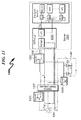
- FIG. 14 (1400) illustrates the power path during power outage, uninterrupted (DC battery backup) power condition.
- battery transfer switch (1220) connects to battery strings (1240) and generator transfer switch (1270) connects to backup generator (1262).
- the server (1205) receives power from the DC battery strings (1240) through the battery transfer switch (1220) to the AC-DC power supply (1250) via current path Ib.
- the generator (1262) provides power through the battery charger (1230), charging battery strings (1240) and also providing power to AC-DC power supply (1250) via current path Ig.
- FIG. 15 is the basic schematic of a boost converter.
- a typical AC-DC power supply has designed-in a boost converter to protect against AC waveform distortion (harmonics, voltage fluctuation, AC power frequency variations) and power line disturbance ( FIG. 1 (0100) CBEMA curve).
- the boost converter can also provide active power factor correction, typically generating a theoretical power factor of over 95%, and also markedly diminishes total harmonics generated by power supply and its load.
- FIG. 16 (1600) illustrates the boost converter current path Ib during DC battery backup mode: the boost converter becomes a DC-DC boost converter with diode D1 and D4 conducting current at all times, while diodes D2 and D3 are back-biased without any current flowing. In this operation, diodes D1 and D2 need to be adequately sized in order to handle the power dissipation either in AC or DC operating mode.
- the novelty here is that during the DC battery backup mode, the battery (1240) can utilize the existing AC-DC power supply (1250) boost converter (1251) as a DC-DC boost converter and convert its output voltage to the required voltage for the IT load, thus eliminating another external boost converter. This arrangement can save cost, space and improve overall system efficiency as well.
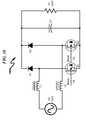
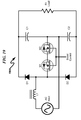
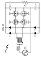
- FIG. 17 (1700) - FIG. 24 (2400) depict various boost converter topologies which can be used as the boost converter (1251) within the context of the present invention. These various topologies can be designed to meet "power line disturbance” (meeting CBEMA curve) and AC waveform distortion (harmonics, voltage fluctuations, AC power line variations) requirements.
- the various topologies depicted include:
- boost converter topologies may be used in this application and that these exemplary circuit topologies do not limit the scope of the claimed invention.
- the various boost and buck-boost converters depicted in FIG. 17 (1700) - FIG. 24 (2400) may be combined with and/or integrated within the DC-DC converter portion of the AC+DC power supply to form an integrated conversion methodology that eliminates the traditional DC-to-AC conversion that is mandated by prior art UPS systems.
- This integration of components improves overall system efficiency while reducing component counts in the overall system architecture.
- FIG. 25 (2500) and FIG. 26 (2600) depict a hybrid system integrated with alternative energy sources.
- the "distributed" uninterrupted power/power conditioner with centralized battery (1201) as shown in FIG. 25 (2500) can be integrated as depicted in FIG. 26 (2600) with solar panel (2611) and solar panel DC-DC converter (2612), fuel cell (2621), fuel cell DC-DC converter (2622), and flywheel (2631). All the alternative energy sources solar panel (2611), fuel cell (2621), and flywheel (2631) can store energy in battery strings (1240) via solar panel DC-DC converter (2612) and fuel cell DC-DC converter (2622).
- the battery strings (1240) can serve as the primary input power source when the server (1205) operates in DC input mode, with the battery transfer switch (1220) in battery mode connecting battery strings (1240) to the input of the server (1205).
- the generator transfer switch (1270) stays in utility mode, charging the battery strings (1240) via charger (1230), and the AC utility serves as a backup power source.
- the battery transfer switch (1220) When the battery string (1240) voltage drains below its specified voltage, the battery transfer switch (1220) will switch to utility mode and server (1205) will be powered by utility (1261).
- FIG. 9 (0900) - FIG. 11 (1100), the rack (0940) may contain multiple servers to provide different computer processing needs.
- the system of "distributed UPS/power conditioner with battery backup energy storage” (1202) and server (1205) is connected in parallel to an identical system consisting of “distributed UPS/power conditioner with battery backup energy storage” (1203) and server (1206).
- Battery strings (1240) contain N strings of batteries to provide backup power energy to server (1205) when the AC power utility (1261) falls out of its normal operation range (when a 120V nominal AC input voltage falls below a first threshold of 90V in any half cycle, or if the RMS voltage drops below a second cycle of 100V for a pre-specified time and conditions which may include but is not limited to brownouts, blackouts, voltage sag, surges, instabilities).
- battery strings (1241) contain N strings of batteries and provide backup energy to the server (1206) when the AC utility power (1263) falls out of its normal operation range.
- the configuration of FIG. 27 (2700) - FIG. 28 (2800) contains a total of 2N strings of batteries to provide 1+1 redundant server backup power.
- Each "distributed UPS/power conditioner with battery backup energy storage" (1202, 1203) performs in the same mode of operation as its counterpart in FIG. 12 (1200).
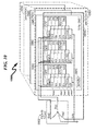
- FIG. 29 (2900) - FIG. 30 (3000) depict a 1+1 redundant system performing the same function as that of FIG. 27 (2700) - FIG. 28 (2800), but with a centralized battery system.
- the battery strings count is 1N instead of the 2N in FIG. 27 (2700) - FIG. 28 (2800).
- This system provides the same redundancy function as in the system of FIG. 27 (2700) - FIG. 28 (2800), but with 1N less battery, one less backup AC generator and one less controller.
- the battery strings (1240) get charged from both AC source (1261, 1263) via battery chargers (1230, 1231) in steady-state condition.
- FIG. 31 (3100) - FIG. 32 (3200) depict the mode of operation of the "1+1 redundancy server with centralized battery" configuration of FIG. 29 (2900) - FIG. 30 (3000).
- controller (1210) of FIG. 29 (2900) - FIG. 30 (3000) senses that the server (1205) input voltage is below its specified range and thereupon sends a command to the battery transfer switch (1220) to operate in DC-battery mode and break away from utility (1261). Battery strings (1240) therefore power the server (1205) via the current path Ib.
- the controller (1210) instructs generator transfer switch (1270) to disconnect from failed AC source (1261) and connects to the backup generator (1262).
- Battery strings (1240) are charged by battery charger (1230) (sourced by generator (1262)), via the current charge path Ig). Meanwhile, they are also charged by the battery charger (1231) (sourced by AC source (1263) phase B) via current path Ic. In this condition, battery strings (1240) provide power to the server (1205), being charged from two backup AC sources: backup generator (1262) and AC source B (1263).
- the controller (1210) of FIG. 29 (2900) - FIG. 30 (3000) is deliberately omitted in FIG. 31 (3100) - FIG. 32 (3200) for sake of brevity and clarity in showing current paths.
- the present invention preferred exemplary system embodiment anticipates a wide variety of variations in the basic theme of construction, but can be generalized as an uninterruptable power supply (UPS) system comprising:
- the present invention preferred exemplary method embodiment anticipates a wide variety of variations in the basic theme of implementation, but can be generalized as an uninterruptable power supply method, the method operating in conjunction with an uninterruptable power supply system comprising:
- the present invention may be embodied in many preferred alternate forms, some of which may incorporate the following structures:
- the present invention anticipates a wide variety of variations in the basic theme of construction.
- the examples presented previously do not represent the entire scope of possible usages. They are meant to cite a few of the almost limitless possibilities.
- This basic system and method may be augmented with a variety of ancillary embodiments, including but not limited to:
- the present invention may be implemented as a computer program product for use with a computerized computing system.
- programs defining the functions defined by the present invention can be written in any appropriate programming language and delivered to a computer in many forms, including but not limited to: (a) information permanently stored on non-writeable storage media (e.g., read-only memory devices such as ROMs or CD-ROM disks); (b) information alterably stored on writeable storage media (e.g., floppy disks and hard drives); and/or (c) information conveyed to a computer through communication media, such as a local area network, a telephone network, or a public network such as the Internet.
- non-writeable storage media e.g., read-only memory devices such as ROMs or CD-ROM disks
- writeable storage media e.g., floppy disks and hard drives
- information conveyed to a computer through communication media such as a local area network, a telephone network, or a public network such as the Internet.
- the present invention system embodiments can incorporate a variety of computer readable media that comprise computer usable medium having computer readable code means embodied therein.
- One skilled in the art will recognize that the software associated with the various processes described herein can be embodied in a wide variety of computer accessible media from which the software is loaded and activated.
- the software associated with the various processes described herein can be embodied in a wide variety of computer accessible media from which the software is loaded and activated.
- the present invention anticipates and includes this type of computer readable media within the scope of the invention.
- Pursuant to In re Nuijten, 500 F.3d 1346 ( Fed. Cir. 2007 ) U.S. Patent Application S/N 09/211,928
- the present invention scope is limited to computer readable media wherein the media is both tangible and non-transitory.
- UPS uninterruptable power supply
- PFC power line conditioning and power factor correction
- the system generally comprises an AC-DC power supply with active PFC (power factor correction) function, a battery transfer switch, an isolated battery charger placed between the utility power source and battery strings, battery strings connecting the battery charger and the battery transfer switch, EMI/Lightning circuitry that provides lighting / line surge protection as well noise suppression functions, and a controller monitoring the quality of the utility power source.
- Uninterruptable power for data centers is achieved in this context via use of the battery strings, battery transfer switch, battery charger, and controller system configuration. Disclosed methods associated with this system generally permit the UPS to operate in a distributed fashion in support of computing systems within data centers.
Landscapes
- Engineering & Computer Science (AREA)
- Theoretical Computer Science (AREA)
- Power Engineering (AREA)
- Physics & Mathematics (AREA)
- General Engineering & Computer Science (AREA)
- General Physics & Mathematics (AREA)
- Business, Economics & Management (AREA)
- Emergency Management (AREA)
- Charge And Discharge Circuits For Batteries Or The Like (AREA)
- Stand-By Power Supply Arrangements (AREA)
Applications Claiming Priority (3)
| Application Number | Priority Date | Filing Date | Title |
|---|---|---|---|
| US201361922311P | 2013-12-31 | 2013-12-31 | |
| US14/461,110 US9047076B1 (en) | 2013-12-31 | 2014-08-15 | Uninterruptable power supply system and method |
| US14/509,454 US9047075B1 (en) | 2013-12-31 | 2014-10-08 | Uninterruptable power supply system and method |
Publications (2)
| Publication Number | Publication Date |
|---|---|
| EP2889985A2 true EP2889985A2 (de) | 2015-07-01 |
| EP2889985A3 EP2889985A3 (de) | 2015-08-19 |
Family
ID=52146248
Family Applications (1)
| Application Number | Title | Priority Date | Filing Date |
|---|---|---|---|
| EP14199244.6A Withdrawn EP2889985A3 (de) | 2013-12-31 | 2014-12-19 | Unterbrechungsfreies Stromversorgungssystem und Verfahren |
Country Status (2)
| Country | Link |
|---|---|
| US (1) | US9047075B1 (de) |
| EP (1) | EP2889985A3 (de) |
Cited By (3)
| Publication number | Priority date | Publication date | Assignee | Title |
|---|---|---|---|---|
| CN107546836A (zh) * | 2016-06-23 | 2018-01-05 | 艾默生网络能源有限公司 | 一种ups电源 |
| US10734813B2 (en) | 2016-02-12 | 2020-08-04 | Indian Space Research Organisation | Triple input smart power supply (TRISP) for desktop PC and other systems using DC as final power source |
| EP3989380A3 (de) * | 2020-10-21 | 2022-08-17 | Schneider Electric IT Corporation | Neues verfahren zur überwindung von spannungs- und strombegrenzungen in elektrischen schaltungen |
Families Citing this family (19)
| Publication number | Priority date | Publication date | Assignee | Title |
|---|---|---|---|---|
| WO2014198044A1 (en) * | 2013-06-13 | 2014-12-18 | Firebright1 Green Energy(Shanghai) Limited. | Battery energy storage system and controlling method |
| US9537341B2 (en) | 2013-12-31 | 2017-01-03 | Lite-On, Inc. | Power supply output configuration system and method |
| US9965365B2 (en) | 2013-12-31 | 2018-05-08 | Lite-On, Inc. | Power supply failover system and method |
| US9509158B2 (en) | 2013-12-31 | 2016-11-29 | Lite-On, Inc. | Power supply configuration system and method |
| US9537351B2 (en) | 2013-12-31 | 2017-01-03 | Lite-On, Inc. | Dual input power supply system and method |
| JP6152241B2 (ja) * | 2014-04-23 | 2017-06-21 | レノボ・シンガポール・プライベート・リミテッド | 電力システム、携帯式電子機器および電力の供給方法 |
| US9783072B1 (en) * | 2014-12-15 | 2017-10-10 | SemaConnect Inc. | System and method for redundantly controlling a dual electric vehicle supply equipment |
| RU2709628C2 (ru) * | 2015-03-17 | 2019-12-19 | Филипс Лайтинг Холдинг Б.В. | Возбудитель по меньшей мере с четырьмя различными состояниями |
| US20170063127A1 (en) * | 2015-08-26 | 2017-03-02 | The Aes Corporation | Battery Backup Capacity Method and System |
| CN108418301B (zh) * | 2018-05-15 | 2024-05-10 | 深圳市菲菱科思通信技术股份有限公司 | 一种双电源输入的自动切换电路 |
| CN109245285B (zh) * | 2018-10-25 | 2023-09-05 | 南方电网科学研究院有限责任公司 | 一种三角形电路的冗余拓扑结构 |
| JP7112942B2 (ja) * | 2018-11-13 | 2022-08-04 | ルネサスエレクトロニクス株式会社 | 電源回路、電源システム、及び電源回路の制御方法 |
| US11418125B2 (en) | 2019-10-25 | 2022-08-16 | The Research Foundation For The State University Of New York | Three phase bidirectional AC-DC converter with bipolar voltage fed resonant stages |
| CN113300453A (zh) * | 2021-05-26 | 2021-08-24 | 宁波荣特电子有限公司 | Eps智能消防应急供电系统 |
| US12578777B2 (en) | 2022-12-20 | 2026-03-17 | Samsung Electronics Co., Ltd. | Systems, methods, and apparatus for providing power to storage devices |
| US12393244B2 (en) | 2022-12-20 | 2025-08-19 | Samsung Electronics Co., Ltd. | Systems, methods, and apparatus for providing power to storage devices |
| US12463444B2 (en) | 2023-03-03 | 2025-11-04 | Yellow Power Systems, LLC | Devices, systems, and methods for a direct-current energy storage to power an alternating current load |
| WO2024186654A1 (en) * | 2023-03-03 | 2024-09-12 | Yellow Power Systems, LLC | Devices, systems, and methods for connecting a direct-current energy storage to an alternating current load |
| CN119675219B (zh) * | 2024-12-03 | 2025-11-18 | 安徽明德源能科技有限责任公司 | 供电模块和数据中心 |
Citations (1)
| Publication number | Priority date | Publication date | Assignee | Title |
|---|---|---|---|---|
| US5710578A (en) | 1987-12-09 | 1998-01-20 | International Business Machines Corporation | Computer program product for utilizing fast polygon fill routines in a graphics display system |
Family Cites Families (8)
| Publication number | Priority date | Publication date | Assignee | Title |
|---|---|---|---|---|
| TWI248567B (en) * | 2004-09-08 | 2006-02-01 | Delta Electronics Inc | Uninterruptible power supply with network hub functions |
| US7852045B2 (en) * | 2007-06-20 | 2010-12-14 | Intel Corporation | Battery charge management using a scheduling application |
| DE102008024222A1 (de) * | 2007-08-14 | 2009-02-26 | Karl-Friedrich Schilling Elektrotechnik Gmbh | Verfahren und Vorrichtung zur Bereitstellung von Regelleistung im Energieversorgungsbereich zur Frequenzstabilisierung eines elektrischen Netzes |
| US8156372B2 (en) * | 2009-01-09 | 2012-04-10 | Broadcom Corporation | Power outage operation of a cable modem |
| US9093861B2 (en) * | 2009-09-16 | 2015-07-28 | Toshiba Mitsubishi-Electric Industrial Systems Corporation | Power conversion system and uninterruptible power supply system |
| KR101166020B1 (ko) * | 2010-05-31 | 2012-07-19 | 삼성에스디아이 주식회사 | 비접촉 충전 시스템 및 이를 포함한 에너지 저장 시스템 |
| JP5611727B2 (ja) * | 2010-08-27 | 2014-10-22 | 三洋電機株式会社 | 電源装置 |
| JP5962101B2 (ja) * | 2012-03-19 | 2016-08-03 | 富士通株式会社 | バックアップ電源装置、電源システム、コンピュータシステム、コンピュータシステムの電源制御方法および電源制御プログラム |
-
2014
- 2014-10-08 US US14/509,454 patent/US9047075B1/en active Active
- 2014-12-19 EP EP14199244.6A patent/EP2889985A3/de not_active Withdrawn
Patent Citations (1)
| Publication number | Priority date | Publication date | Assignee | Title |
|---|---|---|---|---|
| US5710578A (en) | 1987-12-09 | 1998-01-20 | International Business Machines Corporation | Computer program product for utilizing fast polygon fill routines in a graphics display system |
Cited By (6)
| Publication number | Priority date | Publication date | Assignee | Title |
|---|---|---|---|---|
| US10734813B2 (en) | 2016-02-12 | 2020-08-04 | Indian Space Research Organisation | Triple input smart power supply (TRISP) for desktop PC and other systems using DC as final power source |
| CN107546836A (zh) * | 2016-06-23 | 2018-01-05 | 艾默生网络能源有限公司 | 一种ups电源 |
| EP3270486A1 (de) * | 2016-06-23 | 2018-01-17 | Vertiv Tech Co., Ltd. | Unterbrechungsfreie stromversorgung |
| US10454300B2 (en) | 2016-06-23 | 2019-10-22 | Vertiv Tech Co., Ltd. | UPS power supply |
| EP3989380A3 (de) * | 2020-10-21 | 2022-08-17 | Schneider Electric IT Corporation | Neues verfahren zur überwindung von spannungs- und strombegrenzungen in elektrischen schaltungen |
| US11749993B2 (en) | 2020-10-21 | 2023-09-05 | Schneider Electric It Corporation | Method to overcome electrical circuit voltage and current limitations |
Also Published As
| Publication number | Publication date |
|---|---|
| US9047075B1 (en) | 2015-06-02 |
| EP2889985A3 (de) | 2015-08-19 |
Similar Documents
| Publication | Publication Date | Title |
|---|---|---|
| US9444280B2 (en) | Uninterruptable power supply system and method | |
| US9047076B1 (en) | Uninterruptable power supply system and method | |
| US9047075B1 (en) | Uninterruptable power supply system and method | |
| Guerrero et al. | Uninterruptible power supply systems provide protection | |
| Aamir et al. | Uninterruptible power supply (UPS) system | |
| Salomonsson et al. | Low-voltage DC distribution system for commercial power systems with sensitive electronic loads | |
| Backhaus et al. | DC microgrids scoping study. Estimate of technical and economic benefits | |
| Kroposki et al. | Microgrid standards and technologies | |
| EP2036189B1 (de) | Verteilungsarchitektur für ununterbrechbare stromversorgung einer datenzentrale | |
| Boroyevich et al. | Future electronic power distribution systems a contemplative view | |
| EP3141983B1 (de) | Stromversorgungsverfahren und vorrichtung | |
| CN106549486B (zh) | 用于操作不间断电源的系统和方法 | |
| US20140361624A1 (en) | Apparatus and methods for control of load power quality in uninterruptible power systems | |
| US9859749B2 (en) | UPS having a delta converter utilized as input power regulator in a double conversion system | |
| AU2016101769B4 (en) | Power system and method | |
| US20090021963A1 (en) | Uninterruptible power supply, connected to a grid | |
| JP2016042780A (ja) | 無停電電力供給システム、無停電電力供給方法及び記録媒体 | |
| TW201901351A (zh) | 資料中心、電信環境及等效基礎設施的電力之虛擬化 | |
| US20140035376A1 (en) | Uninterruptible power system and method of operating the same | |
| KR102721421B1 (ko) | 고출력 인터리빙 전력 제어를 통한 스마트액티브 고효율 ups 시스템 및 이를 이용한 구현 방법 | |
| Vieira et al. | Hybrid PV-UPS system with multilevel structure of power converters and reliability improvment | |
| WO2012024182A1 (en) | Modular backup power management | |
| Milad | UPS system: how current and future technologies can improve energy efficiency in data centres | |
| Salomonsson et al. | Comparison of different solutions for emergency and standby power systems for commercial consumers | |
| Stepanov et al. | Concept of modular uninterruptible power supply system with alternative energy storages and sources |
Legal Events
| Date | Code | Title | Description |
|---|---|---|---|
| PUAI | Public reference made under article 153(3) epc to a published international application that has entered the european phase |
Free format text: ORIGINAL CODE: 0009012 |
|
| 17P | Request for examination filed |
Effective date: 20141219 |
|
| AK | Designated contracting states |
Kind code of ref document: A2 Designated state(s): AL AT BE BG CH CY CZ DE DK EE ES FI FR GB GR HR HU IE IS IT LI LT LU LV MC MK MT NL NO PL PT RO RS SE SI SK SM TR |
|
| AX | Request for extension of the european patent |
Extension state: BA ME |
|
| PUAL | Search report despatched |
Free format text: ORIGINAL CODE: 0009013 |
|
| AK | Designated contracting states |
Kind code of ref document: A3 Designated state(s): AL AT BE BG CH CY CZ DE DK EE ES FI FR GB GR HR HU IE IS IT LI LT LU LV MC MK MT NL NO PL PT RO RS SE SI SK SM TR |
|
| AX | Request for extension of the european patent |
Extension state: BA ME |
|
| RIC1 | Information provided on ipc code assigned before grant |
Ipc: H02J 9/06 20060101AFI20150715BHEP Ipc: G06F 1/28 20060101ALI20150715BHEP Ipc: G06F 1/26 20060101ALI20150715BHEP |
|
| RAP1 | Party data changed (applicant data changed or rights of an application transferred) |
Owner name: LITE-ON, INC. |
|
| RIN1 | Information on inventor provided before grant (corrected) |
Inventor name: LITE-ON, INC. |
|
| R17P | Request for examination filed (corrected) |
Effective date: 20160216 |
|
| RBV | Designated contracting states (corrected) |
Designated state(s): AL AT BE BG CH CY CZ DE DK EE ES FI FR GB GR HR HU IE IS IT LI LT LU LV MC MK MT NL NO PL PT RO RS SE SI SK SM TR |
|
| STAA | Information on the status of an ep patent application or granted ep patent |
Free format text: STATUS: REQUEST FOR EXAMINATION WAS MADE |
|
| STAA | Information on the status of an ep patent application or granted ep patent |
Free format text: STATUS: THE APPLICATION IS DEEMED TO BE WITHDRAWN |
|
| 18D | Application deemed to be withdrawn |
Effective date: 20170701 |