EP2890272B1 - Cabinet, method for manufacturing a cabinet - Google Patents
Cabinet, method for manufacturing a cabinet Download PDFInfo
- Publication number
- EP2890272B1 EP2890272B1 EP13832303.5A EP13832303A EP2890272B1 EP 2890272 B1 EP2890272 B1 EP 2890272B1 EP 13832303 A EP13832303 A EP 13832303A EP 2890272 B1 EP2890272 B1 EP 2890272B1
- Authority
- EP
- European Patent Office
- Prior art keywords
- cabinet
- side frame
- vertical
- intermediate parts
- beams
- Prior art date
- Legal status (The legal status is an assumption and is not a legal conclusion. Google has not performed a legal analysis and makes no representation as to the accuracy of the status listed.)
- Active
Links
Images










Classifications
-
- A—HUMAN NECESSITIES
- A47—FURNITURE; DOMESTIC ARTICLES OR APPLIANCES; COFFEE MILLS; SPICE MILLS; SUCTION CLEANERS IN GENERAL
- A47B—TABLES; DESKS; OFFICE FURNITURE; CABINETS; DRAWERS; GENERAL DETAILS OF FURNITURE
- A47B47/00—Cabinets, racks or shelf units, characterised by features related to dismountability or building-up from elements
- A47B47/04—Cabinets, racks or shelf units, characterised by features related to dismountability or building-up from elements made mainly of wood or plastics
- A47B47/05—Cabinets, racks or shelf units, characterised by features related to dismountability or building-up from elements made mainly of wood or plastics with panels on a separate frame, e.g. a metal frame
-
- A—HUMAN NECESSITIES
- A47—FURNITURE; DOMESTIC ARTICLES OR APPLIANCES; COFFEE MILLS; SPICE MILLS; SUCTION CLEANERS IN GENERAL
- A47B—TABLES; DESKS; OFFICE FURNITURE; CABINETS; DRAWERS; GENERAL DETAILS OF FURNITURE
- A47B77/00—Kitchen cabinets
- A47B77/02—General layout, e.g. relative arrangement of compartments, working surface or surfaces, supports for apparatus
Definitions
- the object of the invention is a cabinet, such as a kitchen cabinet.
- Known kitchen cabinets, wardrobes and similar cabinets are currently usually made from particleboard so that the particleboard pieces, joined together, form all of the walls of the cabinet.
- the cabinet does not have a separate body, but instead the cover panels made from particleboard form at the same time both the cabinet and the body of the cabinet.
- particleboard is low-cost compared to wood panels and other possible structural panels.
- a sufficiently thick particleboard also gives the cabinet the stiffness and strength required.
- particleboard has many disadvantages which arise from its manufacturing method. Particleboard is always manufactured from wood chips by joining them together by gluing. The chemicals used in gluing are often toxic, while reducing the amount of glue weakens the crush strength of the particleboard. In fact, one of the disadvantages of particleboard is that it crumbles easily when an impact is exerted on the edge of the particleboard.
- the cabinet bodies have most often been manufactured from profiles bent from wood, aluminium profile or steel plate.
- the profiles are cut to a suitable length and joined together using connecting pieces.
- Such solutions have been presented, for example, in publications US-3877765 A , US-3178244 A , US-2007257585 A1 and JP-2010162164 A , where various profiles have been used for manufacturing the cabinet body.
- the cabinet body is formed from plastic or metal profiles such that suitable pieces are cut from them and joined together using separate connecting pieces.
- US 4 378 137 A discloses a cabinet made of moulded plastic known in the state of the art.
- the purpose of the invention is to create a cabinet, such as a kitchen cabinet, which is simpler, more cost-effective and quicker to manufacture. Furthermore, the purpose of the invention is to create a new cabinet structure that is strong, suitable for multiple uses and easily modifiable. The purpose of the invention is also to create a manufacturing method for a cabinet, such as a kitchen cabinet, which does not have the above-mentioned problems and which allows the cabinet to be manufactured in a simpler and more efficient manner. Furthermore, the purpose of the invention is also to create a cabinet system which enables different cabinet combinations to be created easily.
- the cabinet includes two vertical side frames which are essentially rectangular pieces, open in the middle and manufactured by injection moulding from composite material and which have fastening holes for the fastening of possible additional cabinet parts, such as drawers, shelves and/or hinges, and that the horizontal intermediate parts connecting the manufactured from composite material are also beams or profile beams manufactured from composite material.
- the vertical side frames have been connected to one another by using horizontal intermediate parts, which most preferably are light and narrow. Most preferably they have also been manufactured from composite material.
- the cabinet does not necessarily need panels at all but the cabinet can also include panels with one or several parts consisting of wood material.
- a panel manufactured from two or more parts has most preferably an expansion joint which allows the expansion of the panel while the outer dimensions of the side frame remain essentially unchanged.
- the panel can also be manufactured from combinations of different materials, such as, for example, wood and composite.
- a kitchen cabinet set created in this way can be manufactured rapidly. In addition, its structure is strong and withstands different conditions of use. Those sides of the cabinet that remain open can be covered with panels if necessary, or if one wishes to cover them for some other reason.
- the vertical side frames of the cabinet are most preferably essentially rectangular frames, which are open in the middle and made from composite material.
- the cabinets can be equipped with side panels, tops and end panels.
- Most preferably the cabinets are equipped with drawers and/or hinged doors.
- Solid-wood drawers or drawers with wooden face panels, for example, can be used as drawer sets.
- the drawers can also be stackable inside one another.
- the drawers can also be completely or partially manufactured from composite material or recycled materials.
- This kind of frame-like cabinet is very light because the cabinet is formed by vertical frames, which are open in the middle and joined together with narrow and light horizontal transversal parts.
- the frame structure, which forms the cabinet is completely rigid and strong enough without any cover panels. Therefore the cabinet as such is ready for use and no cover panels are necessarily needed at all.
- the cabinet does not need any cover panels at least on the front side of the cabinet.. Only if the side of the cabinet remains visible, it can be covered preferably by a thin and light panel, which forms a visual obstruction. Because in the cabinet there are no panels, which were necessary to form the load bearing body structure, the savings in weight compared to the known cabinet of similar size and made of particleboard can be up to 50%.
- An advantage of the frame-like cabinet is also in that the possible cover panels can be lightweight and easy to fasten. Accordingly the cover panels are also easy to detach and if one wishes easy to change into different panels, for example of different colour.
- the cover panels are also easy to detach and if one wishes easy to change into different panels, for example of different colour.
- the strength of the frame-like cabinet would weaken during the process because the cabinet formed by the frame is rigid enough and strong completely without any panels. This kind of operation is not possible in the known cabinets. If, for example, in a known particleboard cabinet any cabinet body panel is detached, the cabinet will not remain assembled because the panels themselves form the load bearing body structure of the cabinet.
- a kitchen cabinet set is created including several frame-like cabinets, and which kitchen cabinet set is also completely frame-like. Even in that kitchen cabinet set no panels are necessarily needed. If the cabinet set has drawers provided with face panels, these face panels of the drawers form the visual obstruction, which is needed on the front side of the whole cabinet set. If the cabinet set is not placed so that it covers the whole width of a wall of a room and a side of the cabinet set remains visible, a panel can be added to the side of the cabinet set for providing a visual obstruction.
- the cabinets are most preferably equipped with possibilities for placing LED lighting in a glare-free location.
- the side frames of the cabinets can also be designed and dimensioned such that a free space is left between the frame-like cabinet and the wall for placing water pipes, drain pipes and/or electric wires behind the cabinet near the wall.
- the horizontal intermediate parts connecting the vertical side frames manufactured from composite material are also most preferably beams or profile beams manufactured from composite material.
- the vertical side frames of the cabinet have been injection moulded from composite material and they have connection points which have been made in the injection mould for horizontal intermediate parts and screw holes for a door, shelf and/or other cabinet part.
- the side frames have been joined together with horizontal transversal parts or slats, for example quick connections or screws.
- the connection can also additionally have a securing screw.
- the lengths of the transversal parts between the side frames may vary and the cabinets can be combined to make cabinet set of any width. Most preferably, the width of the cabinets assembled using the side frames and intermediate parts in the cabinet system varies, at increments of 10 cm, between 40 and 150 cm.
- the light-weight cabinets thus created can be cost-efficiently equipped for different purposes in the kitchen and in other rooms.
- the cabinets have been designed so that they have all of the fastening and installation holes required by the assembly connections and the various ways of using the cabinets ready in place. This makes it possible to carry out the assembly of the cabinet either at the factory or only later at the installation site.
- the vertical side frames of the cabinet are made of composite material, which contains, mixed together, at least one new or recycled plastic, and at least one filler, such as sawdust, wood fibres, cellulose fibres, reed canary grass or peat.
- the plastic used can also be biodegradable plastic.
- the mixing ratio between the plastic material and the filler can vary greatly according to need, but most preferably, the mixing ratio is, for example, such that there is roughly the same amount of both plastic material and filler in the mixture.
- a cabinet body structure made from composite material compared to current particle board structures Key advantages include lightness, the recyclability and/or renewability of the materials and a substantially smaller carbon footprint during the cabinet's lifecycle.
- the manufacturing materials and labour can also be procured cost-effectively from the vicinity of the manufacturing plant.
- the structure of the cabinet enables its cost-effective transport in pieces and assembly at the installation site as well as possible disassembly and alteration of or addition to the assembly during the cabinet's lifecycle.
- a frame-like cabinet made from composite material is especially well suited for use in kitchen cabinets, because a kitchen cabinet system most preferably only requires three different vertical side frame models, one of which is for the base cabinet, i.e. the countertop cabinet, another for a tall cabinet and a third for an upper cabinet or wall cabinet. With the help of these, it is possible to build and assemble all of the cabinets needed in the kitchen, in which case the countertop cabinet and the tall cabinet can have the same depth, for example 60 cm, in line with standard kitchen cabinet dimensions.
- the upper cabinet or wall cabinet may have a smaller depth dimension.
- the side frame of the upper cabinet has been designed such that the cabinet structure assembled from it can be equipped with doors hinged on both sides, or with sliding doors.
- the side frames of the base cabinet i.e. countertop cabinet have eight superposed rows of holes for fastening drawers.
- the fastening holes have been positioned such that they allow both drawer options divisible by five and drawer options divisible by four, as presented hereinafter.
- the side frames of the tall cabinet have nine superposed rows of drawer fastening holes, which also allow several options for positioning drawers.
- the side frames of all the cabinets also have several shelf bracket holes and door hinge fastening holes.
- the side frames also have holes, through which screws pass to fasten the intermediate parts of the cabinets to the side frames, connecting screw holes for fastening adjacent side frames of the cabinets to one another.
- the side frame is a continuous piece made from composite plastic in a mould, which piece can be perceived as having been formed in such a way that four straight beams with a cross-section resembling an I-beam have been placed in the shape of a frame so that they form the edge portions i.e. the edge beams of the side frame. In this way, the side frame becomes a frame-like continuous piece which is open in the middle.
- the edge beams having a cross-section in the shape of an I-beam one of the I-beam flanges is located on the outer edge of the side frame and the other on the inside of the side frame.
- edge beams as in a conventional I-beam, there are flanges which are wider than the web located in the middle, between the flanges.
- the width of the web then essentially equals the thickness of the side frame.
- the shape of the I-beam provides the side frame with a rigid and strong structure. In addition, significant savings in manufacturing material and reduction of the side frame weight are achieved by narrowing the I-beam web.
- a vertical additional beam In the middle of the side frame, there may be a vertical additional beam, most preferably also with a cross-section resembling an I-beam, in which case the horizontal fasteners of shelves and/or drawers can be attached either to both of the vertical edge beams of the side frame or only to one of the vertical edge beams and to the additional beam in the middle of the side frame.
- one of the vertical edge beams of the side frame can be moved towards the centre, as shown in Fig. 1 , in which case no additional beam is necessarily needed in the middle of the side frame.
- the locations of the fastening holes in both the side frame edge beams having a cross-section in the shape of an I-beam and/or the additional beam have been reinforced so that the side frame is thicker at the location of the holes.
- the side frame thickness at these points most preferably equals the I-beam flange width.
- the side frame can also be reinforced such that, in addition to the edge beams forming the frame, one or several diagonal beams, parallel with the edge beam or directed obliquely, are placed in the middle of the side frame, as shown in the upper cabinet or wall cabinet side frame of Fig. 4 .
- the cabinet is formed of the vertical side frames and the horizontal intermediate parts, which connect the vertical side frames to one another, and the side frame of the cabinet is manufactured from composite material by injection moulding so that the side frame is an essentially rectangular piece, which is open in the middle, and in which fastening holes are formed in the injection moulding phase for the fastening of possible additional cabinet parts, such as drawers, shelves and/or hinges.
- the side frame of the kitchen cabinet is manufactured from composite material, by injection moulding, after which two vertical and essentially rectangular side frames are joined together with horizontal intermediate pieces which also are made of composite material.
- the cover panels of the cabinet it is also possible to use panels that are made of wood or of combinations of materials, in which at least one part is of wood material.
- the panel to be installed in the cabinet are made of wood material, it is preferable to form an expansion joint between the parts, which allows the wood material to expand while the outer dimensions of the side frame or panel remain essentially unchanged.
- the vertical side frames are most preferably manufactured so that the side frame is one single piece. As the side frames need not be assembled from a plurality of parts, as is the case with known methods, this substantially speeds up the assembly of the cabinet.
- the walls of the cabinet according to the invention can alternatively also be formed from two or more plastic composite panels, wood panels or from a combination of a composite panel and a wood panel. Most preferably, an expansion joint is formed between wood panels or other wood material parts, which enables the expansion of the wood material while the outer dimensions of the panel or side frame remain essentially unchanged.
- the vertical side frames of the kitchen cabinet are essentially formed as open rectangular frames in such a way that they are injection moulded in one peace from composite material. Thereby all of the necessary connection points are formed in the vertical side frames during the injection moulding phase, such as various fastening holes for horizontal intermediate parts and screw holes for a door, shelf and/or other cabinet part.
- the vertical side frames are most preferably injection moulded from such composite material that contains a mixture of one or several new or recycled plastic materials, and at least one organic or non-organic filler.
- the filler is most preferably a natural material, such as sawdust, wood fibres, cellulose fibres, reed canary grass or peat.
- Fig. 1 is a side view of the side frame 11 of the cabinet 10 according to the invention.
- the cabinet to which the side frame shown in the example of Fig. 1 belongs is a kitchen base cabinet, i.e. a countertop cabinet.
- the side frame 11 of the cabinet 10 has been made from composite material by injection moulding, whereby the essentially rectangular side frame is manufactured as a completely finished single piece.
- all of the necessary connection points such as, for example, the pin holes 15, the screw holes 16, the connecting screw holes 17, the drawer rail holes 18, the intermediate floor holes 19 and the door hinge holes 20, are already in place for the other parts of the cabinet 10.
- the location and number of the holes can vary according to the size and intended use of the cabinet.
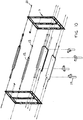
- Fig. 2 shows the assembly of the cabinet 10, wherein the side frames 11 are joined together using intermediate parts 12. Pins 13 and screws 21 are used for the connections. Legs 14 are placed under the cabinet 10.
- Fig. 3 shows an axonometric view of the cabinet 10 assembled. It can be seen from Fig. 3 that in this example, a space is left next to the wall behind the cabinet 10 where cables and/or pipes can be installed. Alternatively, the cables and/or pipes can also be installed, for example, under the cabinet 10, in which case no space is needed for them behind it.
- Shelves and/or drawers are installed as required inside the cabinet 10.
- one or more sides of the cabinet 10 can be clad with side panels and/or a top panel, as required. If the cabinet has no drawers, it can be equipped with a door.
- Fig. 4 shows a side view of the side frame 11 of the cabinet 10.
- the side frame 11 belongs to a kitchen upper cabinet or wall cabinet, for which reason it is narrower than the side frame of the kitchen base cabinet or countertop cabinet shown in Fig. 1 .
- the kitchen upper cabinet of Fig. 4 formed from side frames 11 has a smaller depth than the base cabinet or countertop cabinet of Fig. 3 .
- the side frame 11 of the upper cabinet of Fig. 4 has similar fastening holes for the other parts of the cabinet 10, as in the side frame 11 of the base cabinet, and the assembly of the cabinet 10 takes place in a similar manner.
- the side frame 11 of the upper cabinet has, instead of fastening holes for drawers, fastening holes for shelves or shelf bracket holes 22, where shelves can be placed optionally at any point.
- FIG. 5 shows schematically the assembly of the cabinet 10, wherein the side frames 11 are joined together using intermediate parts 12 and screws 21 and Fig. 6 shows the cabinet assembled.
- the cabinet 10 of Fig. 6 is a kitchen upper cabinet, the depth of which is smaller than that of the kitchen base cabinet or countertop cabinet shown in Fig. 3 .
- Fig. 7 shows a side view of the side frame 11 of the cabinet 10.
- the side frame 11 belongs to a small, tall kitchen cabinet. This side frame 11, too, has similar pin holes 15 and screw holes 16 for assembling the body. In addition, the side frame also has door hinge holes 20.
- Fig. 8 shows schematically the assembly of the of a small, tall kitchen cabinet 10, wherein the side frames 11 are joined together using intermediate parts 12, pins 13 and screws 21.
- the body 10 of the small, tall kitchen cabinet, assembled and with legs 14 attached, is shown in Fig. 9 .
- Fig. 10 shows schematically the assembly of the cabinet 10, which takes place in the same way as presented above.
- the side frames 11 of the cabinet 10 are of injection moulded composite, which means that it has been possible to make all the necessary connection points and holes for the system ready in place at the same time.
- Fig. 11 shows the body 10 of a kitchen base cabinet assembled.
- Figs. 12-14 show the side frame 11 of the cabinet 10 in more detail, seen from different directions.
- the figures show that the side frame 11 made from injection moulded composite has all the necessary connection points and holes ready in place, such as the connecting screw holes 17 and the slide rail fastening holes 18 needed for different drawers of different sizes.
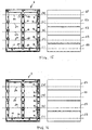
- the side frame 11 which belongs to a kitchen base cabinet, i.e. a countertop cabinet, there are slide rail fastening holes 18 at eight different heights. They have been marked in Fig. 14 as follows: (1), (2), (3), (4), (5), (6), (7) and (8), i.e. the numbering begins at the bottom and increases upwards. Then, almost any kinds of drawers, shelves and doors can be attached to a cabinet 10 having such a side frame 11. Drawers are usually installed using slide rails or similar members to be attached to the side frame 11.
- Figs. 15-18 show different alternatives as examples of drawer or shelf combinations that can be placed in the cabinet 10.
- the slide rail fastening holes 18 used in the different alternatives have been marked using the method of marking described above, whereby the holes are any of the following (1), (2), (3), (4), (5), (6), (7) or (8).
- Fig. 15 shows the side frame 11 of the cabinet 10 and, adjacent to it, a schematic front view of a group of drawers that can be installed in the cabinet body frame that has been assembled using two of the side frames 11 shown in Fig. 15 .
- five slide rails have been attached to the fastening holes 18 of the side frame 11 of the body frame for five shallow drawers 23 of the same size.
- the slide rails of the five drawers have been illustrated in Fig. 15 schematically with dotted lines 24.
- the slide rails of the drawers have been fastened using the fastening holes 18, the location of which in the side frame 11 of Fig. 14 and 15 has been marked with the numbers (1), (2), (4), (6) and (8).
- Fig. 16 is a schematic view of a cabinet 10 similar to that shown in the previous Fig. 15 , wherein four slide rails have been attached to the fastening holes 18 of the slide rails of the side frame 11, for four medium-sized drawers 23 of the same size. Also in this Fig. 15 , the slide rails have been shown schematically with dotted lines 24. However, with the exception of one, the slide rail fastening holes 18 used in this example are not the same as those of the previous figure. Now they are (1), (3), (5) and (7).
- Fig. 17 is a similar schematic view of a cabinet 10, wherein three shallow drawers 23 of the same size and one deep drawer 23 have been attached to the slide rail fastening holes 18.
- the slide rail fastening holes 18 used in this case are (1), (2), (4) and (6).
- one deep drawer 23 has been located in place of the topmost two shallow drawers 23.
- FIG. 18 In the example of Fig. 18 , two medium-sized drawers 23 of the same size and one very deep drawer 23 have been attached to the fastening holes 18 of the slide rails of the cabinet 10 side frame 11.
- the rail holes 18 used are (1), (3) and (5), so that one very deep drawer 23 has been located in place of the topmost two medium-sized drawers 23.
- Figs. 15-18 clearly show how many alternative solutions it is possible to create with the side frame 11 according to the invention. Therefore, the slide rail fastening holes 18 of the side frame 11 are part of a cabinet system which enables a plurality of different combinations of alternative drawers, shelves and doors according to the system. It must be noted that the side frames 11 shown in Figs. 12-18 have, in connection with the rail holes 18 and also outside them, additional holes for different combinations, which have not been presented in further detail.
- the table in the sample case, it is possible to place in a cabinet with height of 715 mm, alternatively, for example, five 140-mm-high drawers, three 140-mm-high drawers and one 280-mm-high drawer, four 175-mm-high drawers or two 175-mm-high drawers and one 350-mm-high drawer.
- Other alternatives are also possible, as shown in Fig. 35 ., for example.
- Figs. 19-21 show schematically a method for forming a cabinet panel in which the drawbacks caused by wood expansion due to moisture variation have been eliminated.
- the cabinet panel can be used as a door, drawer face panel or cabinet side frame of a cabinet, such as a kitchen cabinet, according to the invention.
- Fig. 19 is a schematic view of the assembly of a panel 30, which in this case is a cabinet side frame 11. Essential in this case is that the panel 30 is formed from two or more wood panel parts 31, between which there are expansion joints 34. All parts are attached to one another with intermediate pieces 32, which extend across the panel 30 such that the intermediate pieces 32 are mainly perpendicular to the wood grain of the parts 31 of the panel 30.
- the outermost parts 31 in the panel 30 are attached to the intermediate piece 32 such that their fastening members 33 are as close as possible to the outer edges of the panel 30, i.e. in this case the side frame 11, the expansion of the parts 31 of the panel 30 has no significant impact on the outer dimensions of the entire panel 30, thanks to the expansion joints 34.
- fastening of metal parts, such as hinges etc., which do not expand in the same way, to the panel 30 which forms the side frame 11 or other cabinet part is problem-free.
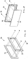
- Figs. 22 and 23 show the assembly of a cabinet 10 formed from panels 30.
- panels 30 not according to the invention in which the drawbacks caused by the expansion of wood due to moisture variation have been eliminated, have, in addition to the side frames 11, also been used in the top and bottom panels which form the intermediate parts 12 of the cabinet 10.
- Fig. 24 shows, seen from the end, the panel 30 of Fig. 21 , which has been formed from three parts 31.
- Each part 31 of the panel 30 is of wood and is fastened to the transversal intermediate piece 32 with fastening members 33 at such a distance from one another that expansion joints 34 remain between the parts 31 of the panel 30.
- the parts 31 of the panel 30 have been fastened to the intermediate piece 32 as close as possible to the entire outer edge of the panel 30, the expansion or shrinkage of the parts 31 of the panel 30 does not significantly affect the outer dimensions of the panel 30.
- the expansion of the parts 31 of the panel 30 only affects the internal structure of the panel 30 in such a way that the size of the expansion joints 34 diminishes or increases without any detrimental effects on the external structure.
- Fig. 25 shows a detail of the structure of the panel 30, showing the end of the intermediate piece 32 connecting the parts 31 of the panel 30 to one another, placed in a transversal groove formed in the panel 30.
- the groove shown in Fig. 25 is a dovetail groove, the side wall angle ⁇ of which is most preferably 60°.
- the intermediate piece 32 remains securely in its place in the groove.
- the groove can also have straight walls or another shape.
- Figs. 26 and 27 show a panel 30 to be assembled from parts and a schematic view of the stages of its assembly.
- This panel 30 can also be used as a cover panel or a side frame 11 of the cabinet body 10. Most preferably, however, it is a door of the cabinet or a face panel of a drawer. As the cabinet doors form relatively large surfaces, manufacturing them from wood panel in the traditional way is problematic. The expansion of wood due to moisture variation easily causes inaccuracy in the installation dimensions.
- the panel 30 shown in Figs. 26 and 27 allows for the expansion and shrinkage of wood due to moisture variation and functions like a wooden panel door, but has a totally different structure.
- the frame 35 of the panel 30 is formed from boards, which results in a stable structure, because the boards do not expand in their longitudinal direction.
- a recess has been formed in the frame 35 in such a way that the inner part 36 of the panel 30, which inner part has been formed from, for example, wood, plywood or other similar material and which is almost the size of the entire frame 35, can be placed in the recess against the frame 35.
- the panel 30 formed this way looks like an almost continuous wood panel, but it nevertheless has an expansion joint 34 on all of its edges.
- the inner part 36 is secured with guide pins 37 such that the gap of the expansion joint 34 is the right size on all sides of the inner part 36.
- the inner part 36 of the panel 30 is locked with locking members 38 such that it remains in contact with the frame 35.
- Fig. 28 shows the panel 30 shown in Figs. 26 and 27 assembled, seen from the front. It can be seen from Fig. 28 that the panel 30 looks like an almost continuous panel, because the inner part 36 of the panel 30, which inner part is almost the size of the frame 35, has been placed in a recess against the frame 35 so that only a narrow rim of the edge of the frame 35 remains visible outside the inner part 36. Between the rim and the inner part 36, there is a small gap which functions as an expansion joint 34 on all sides.
- Fig. 29 shows the panel 30 of Fig. 28 seen from the opposite side. If the panel 30 is, for example, a cabinet door, this is the inner side of the door. It can be seen from Fig. 29 that the inner part 36 of the panel 30 is inside the frame 35 and locked in place with the locking members 38. The guide pins 37 secure the inner part 36 of the panel 30 in place inside the frame 35 in the centre such that a sufficient expansion joint 34 remains on both opposite sides.
- Figs. 30 and 31 show a similar panel 30 as in Figs. 28 and 29 , but this panel is larger and it has two panel-like inner parts 36. These inner parts 36 are kept centrally in place with guide pins 37 and locked into the frame 35 with locking members 38. This way the mutual expansion joint 34 of the inner parts 36 and all of the expansion joints 34 on the edges remain the suitable size regardless of the expansion of the inner parts 36 due to moisture.
- Fig. 32 shows a cross section of the panel 30 of Fig. 28 . It can be seen from Fig. 32 that the thickness of the inner part 36 of the panel 30 has been adjusted such that it forms, together with the frame 35, a solid-looking panel 30, which could be taken for a wood panel formed from one piece. However, in the structure presented according to a preferred embodiment of the invention, there is a separate frame 35, inner part 36 and an expansion joint 34 between these. The structure provides advantageous functionality, so that there are no problems in the panel 30 formed this way, even if the parts of the structure expand due to moisture or correspondingly shrink due to dryness.
- Figs. 33A-33C show side frames 11 of the bodies of the cabinets included in the cabinet system according to a preferred embodiment of the invention.
- Fig. 33A shows the side frame 11 of a kitchen base cabinet, i.e. countertop cabinet
- Fig. 33B shows the side frame 11 of a tall kitchen cabinet
- Fig. 33B shows the side frame 11 of a kitchen upper cabinet or wall cabinet.
- Fig. 33B shows the side frame 11 of a tall kitchen cabinet
- Fig. 33B shows the side frame 11 of a kitchen upper cabinet or wall cabinet.
- All side frames 11 of Figs. 33A-33C are rectangular pieces made from composite plastic.
- the cabinet system includes holes, such as the holes needed during the assembly of the cabinet for connecting the side frames 11 to the other parts of the cabinet. These holes are the pin hole 15 and the screw hole 16.
- the side frames 11 have holes for attaching drawers, shelves, hinges and any other parts included in the system, such as an oven, for example. These holes include the drawer rail role 18, the intermediate floor plane bracket hole 19, the shelf hole 22 and the door hinge hole 20.
- the side frames 11 also have connecting screw holes 17 for connecting adjacent cabinet bodies to one another.
- Figs. 33A and 33B the depth of the side frame 11 of the base cabinet i.e. of a countertop cabinet which is of the same height as a conventional kitchen top, and the depth of the corresponding tall cabinet side frame 11 are the same.
- the depth of the side frame 11 of the upper cabinet or wall cabinet shown in Fig. 33C is smaller.
- Fig. 34 shows cabinets 10 included in the kitchen cabinet system, which have been formed by using side frames 11 according to Figs. 33A-33B , which have been combined and attached to one another in different ways.
- the different assembly alternatives shown in Fig. 34 have been marked A, B, A+A, A+B, B+B and C.
- side frames 11 have been used as follows:
- the heights of the side frame of a kitchen base cabinet i.e. countertop cabinet as in Fig. 33A and of the side frame of an upper kitchen cabinet or wall cabinet as in Fig. 33C are 715 cm and the height of the side frame of a tall kitchen cabinet as in Fig. 33B is 962.5 mm.
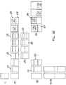
- Fig. 35 shows different alternatives for the cabinets of the kitchen cabinet system according to the invention, seen from the front.
- the different cabinets have been shown in groups on five horizontal lines so that the topmost line has been marked with the letter C. Next under it are the groups A1 and A2. On the fourth line are the groups B1 and B2 and the group B+B is on the bottom line.
- the cabinets illustrated by these groups have been formed in the same way as the combination alternatives of the cabinets 10 shown in Fig. 34 , as follows:
- Figs. 36A-36B show structural parts of the panel 30 used in a cabinet, such as a kitchen cabinet.
- the frame 35 of the panel 30 is formed from boards which are attached to one another with wood pins 39.
- the boards have a recess, in which the inner part 36 formed from, for example, wood, plywood or other similar material can be placed.
- Fig. 37 shows the frame 35 completed, and Fig. 38 shows the complete panel assembled.
- the panel 30 can be used as a door, drawer face panel or cabinet side frame of a kitchen cabinet according to a preferred embodiment of the invention.
- the sectional view of Fig. 39 shows the inner part 36 of the panel 30 inlaid in the recess of the frame 35.
- Fig. 40 shows the side frame 11 of a cabinet 10, in which markings A, B, C and D according to Figs. 41A-41D have been made.
- the markings have most preferably been made such that they have been already engraved in the mould in which the side frame 11 is manufactured using the injection moulding method. In this case, the markings will be on every side frame 11 manufactured from composite material in a mould.
- the hinge fastening holes 20 have been marked with the letter H and the drawer slide rail fastening holes 18 with the number 9.
- the side frame 11 shown in Fig. 41A is a side frame of a tall kitchen cabinet, which side frame has slide rail fastening holes 18 at nine different heights.
- Number 9 means the sequence number of the fastening hole row 18 in this side frame 11, i.e. it is the ninth row starting from the bottom.
- the hinge holes 20 have been marked with the letter H and in Fig. 41C the sequence number 4 of the fastening hole row 18 counting from the bottom.
- the side frame 11 also has both hinge holes 20 and fastening holes 18, the sequence number of which is 1, i.e. it is the first row starting from the bottom.
- Fig. 42 shows a cross-section of the edge beam located at the upper edge of the side frame 11 of Fig 40 .
- the edge beam of the side frame 11 is, in its cross-section, the shape of an I-beam, such that its flanges 26 are wider than the web 27 located between the flanges in the middle.
- the width of the flanges 26 determines at the same time the thickness of the side frame 11. This ways the structure of the side frame 11 becomes lightweight and strong.
- the web has been reinforced and thickened at the rail fastening hole 18, the hinge fastening hole 20 and other fastening points located in the web 27 such that its thickness equals the thickness of the side frame 11 at the flanges 26.
- Fig. 42 shows 10 a kitchen cabinet set, which has been assembled by placing cabinets 10 side by side and fastening them to each other.
- Each cabinet 10 is formed of two side frames, which are open in the middle, the side frames being joined together with narrow and light horizontal transversal parts. Thereby the structure of the whole cabinet set is light, completely rigid and strong without any cover panels.
- the adjacent cabinets have been attached to one another so that the adjacent vertical and open side frames of the two adjacent cabinets are attached and locked to one another. Therefore between the cabinets there is always two side frames locked to one another, in which case the structure of the cabinet set will be very strong, due to that the whole cabinet set is completely a frame structure.
- the panel or plane forming part of a cabinet can be formed from injection moulded composite material, from a wood panel formed from two or more wood parts, in which wood panel the drawbacks related to the expansion or shrinkage of wood due to moisture variation have been eliminated, or from a combination of injection moulded composite material and a wood structure. All alternative structures and/or combinations thereof can be included in a cabinet system in which different drawers, shelves or doors can be fitted to the cabinet alternatively in a number of different ways.
Landscapes
- Life Sciences & Earth Sciences (AREA)
- Engineering & Computer Science (AREA)
- Wood Science & Technology (AREA)
- Assembled Shelves (AREA)
- Compositions Of Macromolecular Compounds (AREA)
Priority Applications (5)
| Application Number | Priority Date | Filing Date | Title |
|---|---|---|---|
| HRP20190229TT HRP20190229T1 (hr) | 2012-08-29 | 2013-08-29 | Ormar, postupak za izradu ormara |
| SI201331341T SI2890272T1 (sl) | 2012-08-29 | 2013-08-29 | Omarica, postopek izdelave omarice |
| SM20190123T SMT201900123T1 (it) | 2012-08-29 | 2013-08-29 | Mobile, metodo per produrre un mobile |
| RS20190193A RS58386B1 (sr) | 2012-08-29 | 2013-08-29 | Ormarić, postupak za proizvodnju ormarića |
| PL13832303T PL2890272T3 (pl) | 2012-08-29 | 2013-08-29 | Szafka, sposób produkcji szafki |
Applications Claiming Priority (5)
| Application Number | Priority Date | Filing Date | Title |
|---|---|---|---|
| FI20120286 | 2012-08-29 | ||
| FI20120316 | 2012-09-26 | ||
| FI20130029 | 2013-01-29 | ||
| FI20130031 | 2013-01-30 | ||
| PCT/FI2013/000031 WO2014033358A1 (en) | 2012-08-29 | 2013-08-29 | Cabinet, method for manufacturing a cabinet and cabinet system |
Publications (3)
| Publication Number | Publication Date |
|---|---|
| EP2890272A1 EP2890272A1 (en) | 2015-07-08 |
| EP2890272A4 EP2890272A4 (en) | 2016-06-08 |
| EP2890272B1 true EP2890272B1 (en) | 2018-11-14 |
Family
ID=50182573
Family Applications (1)
| Application Number | Title | Priority Date | Filing Date |
|---|---|---|---|
| EP13832303.5A Active EP2890272B1 (en) | 2012-08-29 | 2013-08-29 | Cabinet, method for manufacturing a cabinet |
Country Status (13)
| Country | Link |
|---|---|
| EP (1) | EP2890272B1 (pt) |
| CY (1) | CY1121434T1 (pt) |
| DK (1) | DK2890272T3 (pt) |
| ES (1) | ES2711193T3 (pt) |
| HR (1) | HRP20190229T1 (pt) |
| HU (1) | HUE042416T2 (pt) |
| LT (1) | LT2890272T (pt) |
| PL (1) | PL2890272T3 (pt) |
| PT (1) | PT2890272T (pt) |
| RS (1) | RS58386B1 (pt) |
| SI (1) | SI2890272T1 (pt) |
| SM (1) | SMT201900123T1 (pt) |
| WO (1) | WO2014033358A1 (pt) |
Families Citing this family (7)
| Publication number | Priority date | Publication date | Assignee | Title |
|---|---|---|---|---|
| CN107198372B (zh) * | 2017-06-28 | 2023-04-25 | 北京西科盛世通酒店会展设备制造有限公司 | 便于拆卸可更换面板的布菲台 |
| GB2570098B (en) * | 2017-11-01 | 2021-04-14 | Extreme Logic Kitchens Ltd | A workframe |
| CN208755370U (zh) * | 2017-11-30 | 2019-04-19 | 苏州工业园区得意机电设备有限公司 | 内部管路集成布置的金属橱柜 |
| US11253060B2 (en) * | 2018-10-31 | 2022-02-22 | American Woodmark Corporation | Modular enclosure system |
| IT201900018923A1 (it) * | 2019-10-15 | 2021-04-15 | Officine Gullo S R L | Una struttura portante in metallo con rivestimento in un predeterminato materiale, al fine di formare un modulo facente parte di un mobilio per la cucina |
| DE202021103742U1 (de) * | 2021-07-13 | 2021-08-03 | Häfele SE & Co KG | Schrankkorpus-Modulbausystem in Endlosbauweise sowie zugehöriger Schrankkorpus |
| US20240016289A1 (en) * | 2022-07-15 | 2024-01-18 | Capsule Manufacturing Inc. | Modular millwork method and apparatus |
Family Cites Families (7)
| Publication number | Priority date | Publication date | Assignee | Title |
|---|---|---|---|---|
| FR1439194A (fr) * | 1965-04-07 | 1966-05-20 | Cadre pour construction de meubles transformables | |
| US3926486A (en) * | 1972-01-27 | 1975-12-16 | Gen Electric | Modular furnishings |
| US3877765A (en) * | 1972-08-14 | 1975-04-15 | Mpc Corp | Furniture structure |
| US4378137A (en) * | 1981-04-09 | 1983-03-29 | The Singer Company | Modular furniture construction |
| US20050168115A1 (en) * | 2004-02-04 | 2005-08-04 | Brian Moon | Drawer cabinet storage kit |
| WO2009066333A1 (en) * | 2008-02-05 | 2009-05-28 | Giorgio Caporaso | Modular furnishing structure unlimitately composable in different forms for different uses |
| CN202021053U (zh) * | 2011-04-01 | 2011-11-02 | 肖智雄 | 改良改性abs实验室储物柜 |
-
2013
- 2013-08-29 RS RS20190193A patent/RS58386B1/sr unknown
- 2013-08-29 DK DK13832303.5T patent/DK2890272T3/en active
- 2013-08-29 PT PT13832303T patent/PT2890272T/pt unknown
- 2013-08-29 HR HRP20190229TT patent/HRP20190229T1/hr unknown
- 2013-08-29 PL PL13832303T patent/PL2890272T3/pl unknown
- 2013-08-29 SI SI201331341T patent/SI2890272T1/sl unknown
- 2013-08-29 WO PCT/FI2013/000031 patent/WO2014033358A1/en not_active Ceased
- 2013-08-29 ES ES13832303T patent/ES2711193T3/es active Active
- 2013-08-29 EP EP13832303.5A patent/EP2890272B1/en active Active
- 2013-08-29 SM SM20190123T patent/SMT201900123T1/it unknown
- 2013-08-29 LT LTEP13832303.5T patent/LT2890272T/lt unknown
- 2013-08-29 HU HUE13832303A patent/HUE042416T2/hu unknown
-
2019
- 2019-02-08 CY CY20191100174T patent/CY1121434T1/el unknown
Non-Patent Citations (1)
| Title |
|---|
| None * |
Also Published As
| Publication number | Publication date |
|---|---|
| LT2890272T (lt) | 2019-03-25 |
| WO2014033358A1 (en) | 2014-03-06 |
| SI2890272T1 (sl) | 2019-04-30 |
| PL2890272T3 (pl) | 2019-05-31 |
| RS58386B1 (sr) | 2019-04-30 |
| SMT201900123T1 (it) | 2019-05-10 |
| ES2711193T3 (es) | 2019-04-30 |
| HUE042416T2 (hu) | 2019-07-29 |
| DK2890272T3 (en) | 2019-03-04 |
| EP2890272A1 (en) | 2015-07-08 |
| PT2890272T (pt) | 2019-03-28 |
| EP2890272A4 (en) | 2016-06-08 |
| CY1121434T1 (el) | 2020-05-29 |
| HRP20190229T1 (hr) | 2019-04-05 |
Similar Documents
| Publication | Publication Date | Title |
|---|---|---|
| EP2890272B1 (en) | Cabinet, method for manufacturing a cabinet | |
| US11680596B2 (en) | Assembled product and a method of assembling the assembled product | |
| RU2060715C1 (ru) | Предмет сборно-разборной мебели | |
| EP2702899A1 (en) | A cabinet, a method for manufacturing the cabinet and a cabinet system | |
| US6017107A (en) | Support frame for making furniture | |
| KR101380979B1 (ko) | 책장 조립구조 | |
| US20230127173A1 (en) | Prefabricated Gate Assembly | |
| US6017093A (en) | Rectilinear cross-sectional beam furniture, furniture design and furniture production | |
| US3200962A (en) | Composite furniture assembly | |
| US20110068668A1 (en) | Cabinet assembly and method | |
| AU2012261999B2 (en) | Semi-full access and full access framed cabinetry | |
| KR20130060417A (ko) | 조립식 가구 | |
| CN102635775A (zh) | 带t形槽的铝型材立柱及利用其制造的桌、架、柜、栏、屋 | |
| CN203182363U (zh) | 一种实木拼板的柜子 | |
| EP1617744A1 (en) | Modular cupboard structure | |
| RU231550U1 (ru) | Дверное полотно | |
| KR20090010039U (ko) | 판넬과 판넬을 수직, 수평하게 연결하여 조립하는 조립식가구 | |
| RU231586U1 (ru) | Дверное полотно | |
| CN223640358U (zh) | 一种环保原木柜体 | |
| JP7591207B2 (ja) | 分割型引戸収納ユニット家具 | |
| KR200297148Y1 (ko) | 조립식 가구의 조립구조 | |
| KR100200952B1 (ko) | 조립식 가구용 프라스틱 패널소재 | |
| JP7712240B2 (ja) | 脚付き家具 | |
| CN202484576U (zh) | 带t形槽的铝型材立柱 | |
| RU202222U1 (ru) | Панель раздвижной двери или перегородки |
Legal Events
| Date | Code | Title | Description |
|---|---|---|---|
| PUAI | Public reference made under article 153(3) epc to a published international application that has entered the european phase |
Free format text: ORIGINAL CODE: 0009012 |
|
| 17P | Request for examination filed |
Effective date: 20150330 |
|
| AK | Designated contracting states |
Kind code of ref document: A1 Designated state(s): AL AT BE BG CH CY CZ DE DK EE ES FI FR GB GR HR HU IE IS IT LI LT LU LV MC MK MT NL NO PL PT RO RS SE SI SK SM TR |
|
| AX | Request for extension of the european patent |
Extension state: BA ME |
|
| DAX | Request for extension of the european patent (deleted) | ||
| REG | Reference to a national code |
Ref country code: DE Ref legal event code: R079 Ref document number: 602013046852 Country of ref document: DE Free format text: PREVIOUS MAIN CLASS: A47B0077000000 Ipc: A47B0047040000 |
|
| RA4 | Supplementary search report drawn up and despatched (corrected) |
Effective date: 20160510 |
|
| RIC1 | Information provided on ipc code assigned before grant |
Ipc: A47B 47/04 20060101AFI20160503BHEP Ipc: A47B 77/02 20060101ALI20160503BHEP |
|
| STAA | Information on the status of an ep patent application or granted ep patent |
Free format text: STATUS: EXAMINATION IS IN PROGRESS |
|
| 17Q | First examination report despatched |
Effective date: 20170717 |
|
| GRAP | Despatch of communication of intention to grant a patent |
Free format text: ORIGINAL CODE: EPIDOSNIGR1 |
|
| STAA | Information on the status of an ep patent application or granted ep patent |
Free format text: STATUS: GRANT OF PATENT IS INTENDED |
|
| INTG | Intention to grant announced |
Effective date: 20180108 |
|
| GRAS | Grant fee paid |
Free format text: ORIGINAL CODE: EPIDOSNIGR3 |
|
| GRAJ | Information related to disapproval of communication of intention to grant by the applicant or resumption of examination proceedings by the epo deleted |
Free format text: ORIGINAL CODE: EPIDOSDIGR1 |
|
| GRAL | Information related to payment of fee for publishing/printing deleted |
Free format text: ORIGINAL CODE: EPIDOSDIGR3 |
|
| STAA | Information on the status of an ep patent application or granted ep patent |
Free format text: STATUS: EXAMINATION IS IN PROGRESS |
|
| GRAP | Despatch of communication of intention to grant a patent |
Free format text: ORIGINAL CODE: EPIDOSNIGR1 |
|
| STAA | Information on the status of an ep patent application or granted ep patent |
Free format text: STATUS: GRANT OF PATENT IS INTENDED |
|
| INTC | Intention to grant announced (deleted) | ||
| INTG | Intention to grant announced |
Effective date: 20180601 |
|
| GRAA | (expected) grant |
Free format text: ORIGINAL CODE: 0009210 |
|
| STAA | Information on the status of an ep patent application or granted ep patent |
Free format text: STATUS: THE PATENT HAS BEEN GRANTED |
|
| AK | Designated contracting states |
Kind code of ref document: B1 Designated state(s): AL AT BE BG CH CY CZ DE DK EE ES FI FR GB GR HR HU IE IS IT LI LT LU LV MC MK MT NL NO PL PT RO RS SE SI SK SM TR |
|
| REG | Reference to a national code |
Ref country code: AT Ref legal event code: REF Ref document number: 1063791 Country of ref document: AT Kind code of ref document: T Effective date: 20181115 Ref country code: CH Ref legal event code: EP |
|
| REG | Reference to a national code |
Ref country code: DE Ref legal event code: R096 Ref document number: 602013046852 Country of ref document: DE |
|
| REG | Reference to a national code |
Ref country code: IE Ref legal event code: FG4D |
|
| REG | Reference to a national code |
Ref country code: HR Ref legal event code: TUEP Ref document number: P20190229 Country of ref document: HR |
|
| REG | Reference to a national code |
Ref country code: RO Ref legal event code: EPE |
|
| REG | Reference to a national code |
Ref country code: DK Ref legal event code: T3 Effective date: 20190225 |
|
| REG | Reference to a national code |
Ref country code: NL Ref legal event code: FP |
|
| REG | Reference to a national code |
Ref country code: SE Ref legal event code: TRGR |
|
| REG | Reference to a national code |
Ref country code: PT Ref legal event code: SC4A Ref document number: 2890272 Country of ref document: PT Date of ref document: 20190328 Kind code of ref document: T Free format text: AVAILABILITY OF NATIONAL TRANSLATION Effective date: 20190313 |
|
| REG | Reference to a national code |
Ref country code: HR Ref legal event code: T1PR Ref document number: P20190229 Country of ref document: HR |
|
| REG | Reference to a national code |
Ref country code: EE Ref legal event code: FG4A Ref document number: E016880 Country of ref document: EE Effective date: 20190214 |
|
| REG | Reference to a national code |
Ref country code: ES Ref legal event code: FG2A Ref document number: 2711193 Country of ref document: ES Kind code of ref document: T3 Effective date: 20190430 |
|
| REG | Reference to a national code |
Ref country code: NO Ref legal event code: T2 Effective date: 20181114 |
|
| REG | Reference to a national code |
Ref country code: SK Ref legal event code: T3 Ref document number: E 30057 Country of ref document: SK |
|
| REG | Reference to a national code |
Ref country code: GR Ref legal event code: EP Ref document number: 20190400448 Country of ref document: GR Effective date: 20190509 |
|
| REG | Reference to a national code |
Ref country code: HU Ref legal event code: AG4A Ref document number: E042416 Country of ref document: HU |
|
| REG | Reference to a national code |
Ref country code: DE Ref legal event code: R097 Ref document number: 602013046852 Country of ref document: DE |
|
| REG | Reference to a national code |
Ref country code: HR Ref legal event code: ODRP Ref document number: P20190229 Country of ref document: HR Payment date: 20190820 Year of fee payment: 7 |
|
| PLBE | No opposition filed within time limit |
Free format text: ORIGINAL CODE: 0009261 |
|
| STAA | Information on the status of an ep patent application or granted ep patent |
Free format text: STATUS: NO OPPOSITION FILED WITHIN TIME LIMIT |
|
| 26N | No opposition filed |
Effective date: 20190815 |
|
| REG | Reference to a national code |
Ref country code: HR Ref legal event code: ODRP Ref document number: P20190229 Country of ref document: HR Payment date: 20200820 Year of fee payment: 8 |
|
| REG | Reference to a national code |
Ref country code: AT Ref legal event code: UEP Ref document number: 1063791 Country of ref document: AT Kind code of ref document: T Effective date: 20181114 |
|
| REG | Reference to a national code |
Ref country code: HR Ref legal event code: ODRP Ref document number: P20190229 Country of ref document: HR Payment date: 20210809 Year of fee payment: 9 |
|
| REG | Reference to a national code |
Ref country code: HR Ref legal event code: ODRP Ref document number: P20190229 Country of ref document: HR Payment date: 20220711 Year of fee payment: 10 |
|
| REG | Reference to a national code |
Ref country code: HR Ref legal event code: ODRP Ref document number: P20190229 Country of ref document: HR Payment date: 20230809 Year of fee payment: 11 |
|
| REG | Reference to a national code |
Ref country code: HR Ref legal event code: ODRP Ref document number: P20190229 Country of ref document: HR Payment date: 20240717 Year of fee payment: 12 |
|
| REG | Reference to a national code |
Ref country code: HR Ref legal event code: ODRP Ref document number: P20190229 Country of ref document: HR Payment date: 20250807 Year of fee payment: 13 |
|
| PGFP | Annual fee paid to national office [announced via postgrant information from national office to epo] |
Ref country code: LU Payment date: 20250804 Year of fee payment: 13 Ref country code: NL Payment date: 20250801 Year of fee payment: 13 |
|
| PGFP | Annual fee paid to national office [announced via postgrant information from national office to epo] |
Ref country code: HU Payment date: 20250805 Year of fee payment: 13 |
|
| PGFP | Annual fee paid to national office [announced via postgrant information from national office to epo] |
Ref country code: SM Payment date: 20250807 Year of fee payment: 13 |
|
| PGFP | Annual fee paid to national office [announced via postgrant information from national office to epo] |
Ref country code: FI Payment date: 20250807 Year of fee payment: 13 Ref country code: PT Payment date: 20250731 Year of fee payment: 13 |
|
| PGFP | Annual fee paid to national office [announced via postgrant information from national office to epo] |
Ref country code: LT Payment date: 20250805 Year of fee payment: 13 Ref country code: DE Payment date: 20250801 Year of fee payment: 13 Ref country code: DK Payment date: 20250813 Year of fee payment: 13 |
|
| PGFP | Annual fee paid to national office [announced via postgrant information from national office to epo] |
Ref country code: MC Payment date: 20250808 Year of fee payment: 13 Ref country code: NO Payment date: 20250808 Year of fee payment: 13 Ref country code: GR Payment date: 20250807 Year of fee payment: 13 |
|
| PGFP | Annual fee paid to national office [announced via postgrant information from national office to epo] |
Ref country code: TR Payment date: 20250805 Year of fee payment: 13 Ref country code: PL Payment date: 20250827 Year of fee payment: 13 Ref country code: IT Payment date: 20250801 Year of fee payment: 13 |
|
| PGFP | Annual fee paid to national office [announced via postgrant information from national office to epo] |
Ref country code: BE Payment date: 20250807 Year of fee payment: 13 Ref country code: BG Payment date: 20250814 Year of fee payment: 13 Ref country code: GB Payment date: 20250814 Year of fee payment: 13 |
|
| PGFP | Annual fee paid to national office [announced via postgrant information from national office to epo] |
Ref country code: HR Payment date: 20250807 Year of fee payment: 13 |
|
| PGFP | Annual fee paid to national office [announced via postgrant information from national office to epo] |
Ref country code: AL Payment date: 20250815 Year of fee payment: 13 Ref country code: AT Payment date: 20250806 Year of fee payment: 13 Ref country code: FR Payment date: 20250814 Year of fee payment: 13 |
|
| PGFP | Annual fee paid to national office [announced via postgrant information from national office to epo] |
Ref country code: MT Payment date: 20250814 Year of fee payment: 13 Ref country code: CH Payment date: 20250901 Year of fee payment: 13 Ref country code: SE Payment date: 20250807 Year of fee payment: 13 |
|
| PGFP | Annual fee paid to national office [announced via postgrant information from national office to epo] |
Ref country code: RS Payment date: 20250806 Year of fee payment: 13 Ref country code: EE Payment date: 20250808 Year of fee payment: 13 Ref country code: CZ Payment date: 20250804 Year of fee payment: 13 Ref country code: IE Payment date: 20250801 Year of fee payment: 13 |
|
| PGFP | Annual fee paid to national office [announced via postgrant information from national office to epo] |
Ref country code: RO Payment date: 20250805 Year of fee payment: 13 |
|
| PGFP | Annual fee paid to national office [announced via postgrant information from national office to epo] |
Ref country code: SK Payment date: 20250801 Year of fee payment: 13 |
|
| PGFP | Annual fee paid to national office [announced via postgrant information from national office to epo] |
Ref country code: IS Payment date: 20250811 Year of fee payment: 13 |
|
| PGFP | Annual fee paid to national office [announced via postgrant information from national office to epo] |
Ref country code: LV Payment date: 20250807 Year of fee payment: 13 |
|
| PGFP | Annual fee paid to national office [announced via postgrant information from national office to epo] |
Ref country code: SI Payment date: 20250804 Year of fee payment: 13 |
|
| PGFP | Annual fee paid to national office [announced via postgrant information from national office to epo] |
Ref country code: MK Payment date: 20240718 Year of fee payment: 12 |
|
| PGFP | Annual fee paid to national office [announced via postgrant information from national office to epo] |
Ref country code: CY Payment date: 20250806 Year of fee payment: 13 |
|
| PGFP | Annual fee paid to national office [announced via postgrant information from national office to epo] |
Ref country code: ES Payment date: 20251114 Year of fee payment: 13 |