EP2890992B1 - Vorrichtung zur messung von magnetfeldern mit laplace-kraft - Google Patents
Vorrichtung zur messung von magnetfeldern mit laplace-kraft Download PDFInfo
- Publication number
- EP2890992B1 EP2890992B1 EP13756434.0A EP13756434A EP2890992B1 EP 2890992 B1 EP2890992 B1 EP 2890992B1 EP 13756434 A EP13756434 A EP 13756434A EP 2890992 B1 EP2890992 B1 EP 2890992B1
- Authority
- EP
- European Patent Office
- Prior art keywords
- rigid frame
- axis
- substrate
- rotation
- frame
- Prior art date
- Legal status (The legal status is an assumption and is not a legal conclusion. Google has not performed a legal analysis and makes no representation as to the accuracy of the status listed.)
- Not-in-force
Links
- 239000000758 substrate Substances 0.000 claims description 64
- 239000004020 conductor Substances 0.000 claims description 47
- 238000006073 displacement reaction Methods 0.000 claims description 13
- 239000000463 material Substances 0.000 claims description 13
- 238000004804 winding Methods 0.000 claims description 6
- 230000005484 gravity Effects 0.000 claims description 5
- 230000004044 response Effects 0.000 claims description 2
- 239000011800 void material Substances 0.000 claims 6
- 239000010410 layer Substances 0.000 description 52
- 238000004519 manufacturing process Methods 0.000 description 13
- 230000035945 sensitivity Effects 0.000 description 13
- 238000005259 measurement Methods 0.000 description 10
- 230000001133 acceleration Effects 0.000 description 7
- 239000010703 silicon Substances 0.000 description 7
- 230000000694 effects Effects 0.000 description 6
- 229910052710 silicon Inorganic materials 0.000 description 6
- 238000007906 compression Methods 0.000 description 5
- 239000012777 electrically insulating material Substances 0.000 description 5
- 238000000034 method Methods 0.000 description 5
- 238000005452 bending Methods 0.000 description 4
- 238000005530 etching Methods 0.000 description 4
- 239000004065 semiconductor Substances 0.000 description 4
- 230000008901 benefit Effects 0.000 description 3
- 239000002184 metal Substances 0.000 description 3
- 238000000206 photolithography Methods 0.000 description 3
- 239000003990 capacitor Substances 0.000 description 2
- 230000006835 compression Effects 0.000 description 2
- 238000000708 deep reactive-ion etching Methods 0.000 description 2
- 229940082150 encore Drugs 0.000 description 2
- 238000004377 microelectronic Methods 0.000 description 2
- 230000008569 process Effects 0.000 description 2
- 230000001131 transforming effect Effects 0.000 description 2
- 229910000927 Ge alloy Inorganic materials 0.000 description 1
- 241000446313 Lamella Species 0.000 description 1
- 229910000676 Si alloy Inorganic materials 0.000 description 1
- 229910052581 Si3N4 Inorganic materials 0.000 description 1
- VYPSYNLAJGMNEJ-UHFFFAOYSA-N Silicium dioxide Chemical compound O=[Si]=O VYPSYNLAJGMNEJ-UHFFFAOYSA-N 0.000 description 1
- 229910000577 Silicon-germanium Inorganic materials 0.000 description 1
- 240000008042 Zea mays Species 0.000 description 1
- 230000003321 amplification Effects 0.000 description 1
- 230000004888 barrier function Effects 0.000 description 1
- 230000015572 biosynthetic process Effects 0.000 description 1
- 230000008859 change Effects 0.000 description 1
- 239000012141 concentrate Substances 0.000 description 1
- 238000005520 cutting process Methods 0.000 description 1
- 230000001419 dependent effect Effects 0.000 description 1
- 239000011810 insulating material Substances 0.000 description 1
- 239000012212 insulator Substances 0.000 description 1
- 238000003199 nucleic acid amplification method Methods 0.000 description 1
- 238000005457 optimization Methods 0.000 description 1
- 230000010355 oscillation Effects 0.000 description 1
- 239000011347 resin Substances 0.000 description 1
- 229920005989 resin Polymers 0.000 description 1
- HQVNEWCFYHHQES-UHFFFAOYSA-N silicon nitride Chemical compound N12[Si]34N5[Si]62N3[Si]51N64 HQVNEWCFYHHQES-UHFFFAOYSA-N 0.000 description 1
- 229910052814 silicon oxide Inorganic materials 0.000 description 1
- 239000002356 single layer Substances 0.000 description 1
- 239000012808 vapor phase Substances 0.000 description 1
Images


Classifications
-
- G—PHYSICS
- G01—MEASURING; TESTING
- G01D—MEASURING NOT SPECIALLY ADAPTED FOR A SPECIFIC VARIABLE; ARRANGEMENTS FOR MEASURING TWO OR MORE VARIABLES NOT COVERED IN A SINGLE OTHER SUBCLASS; TARIFF METERING APPARATUS; MEASURING OR TESTING NOT OTHERWISE PROVIDED FOR
- G01D5/00—Mechanical means for transferring the output of a sensing member; Means for converting the output of a sensing member to another variable where the form or nature of the sensing member does not constrain the means for converting; Transducers not specially adapted for a specific variable
- G01D5/12—Mechanical means for transferring the output of a sensing member; Means for converting the output of a sensing member to another variable where the form or nature of the sensing member does not constrain the means for converting; Transducers not specially adapted for a specific variable using electric or magnetic means
- G01D5/14—Mechanical means for transferring the output of a sensing member; Means for converting the output of a sensing member to another variable where the form or nature of the sensing member does not constrain the means for converting; Transducers not specially adapted for a specific variable using electric or magnetic means influencing the magnitude of a current or voltage
-
- G—PHYSICS
- G01—MEASURING; TESTING
- G01R—MEASURING ELECTRIC VARIABLES; MEASURING MAGNETIC VARIABLES
- G01R33/00—Arrangements or instruments for measuring magnetic variables
- G01R33/02—Measuring direction or magnitude of magnetic fields or magnetic flux
- G01R33/028—Electrodynamic magnetometers
- G01R33/0286—Electrodynamic magnetometers comprising microelectromechanical systems [MEMS]
-
- G—PHYSICS
- G01—MEASURING; TESTING
- G01R—MEASURING ELECTRIC VARIABLES; MEASURING MAGNETIC VARIABLES
- G01R33/00—Arrangements or instruments for measuring magnetic variables
- G01R33/02—Measuring direction or magnitude of magnetic fields or magnetic flux
- G01R33/038—Measuring direction or magnitude of magnetic fields or magnetic flux using permanent magnets, e.g. balances, torsion devices
Definitions
- the invention relates to a Laplace force magnetic field measuring device.
- Laplace's force is also known as "Lorentz force”.
- Laplace force magnetic field meters can be used to measure a component of the Earth's magnetic field or a component of a magnetic field generated by an electrical conductor or other magnetic field source.
- component of the magnetic field is meant the amplitude of the orthogonal projection of the magnetic field on a measurement axis of the measuring device.
- the measuring device of A1 is working properly. It is however desirable to improve its sensitivity.
- the Laplace force magnetic field measurement devices adopt a particular conformation which limits the number of turns of the electrical conductor to less than a single turn. It is however desirable to have a conformation of the measuring device which does not limit the number of turns of the electrical conductor.
- the measuring device comprises the features of claim 2.
- the beam of the sensor is directly attached, on one side, to the first rigid frame and, on the other hand, to the substrate.
- the rigid frame forms a lever that amplifies all the more Laplace force exerted that the first end of the beam is close to the axis of rotation.
- the first end of the beam is much closer to the axis of rotation than the location where the Laplace force applies to the first frame.
- the stress sensors are integrated on lateral flexible strips allowing the frame to pivot about its axis of rotation. Under these conditions, so that the sensors can measure a variation of stress, these slats must be deformable. Otherwise, the sensors would not measure any signals. Therefore, since each lamella is deformable does not benefit directly from a mechanical lever arm effect in the case of A1 measuring device. This explains why the measuring device of A1 is less sensitive than that described above.
- each element can be sized individually to achieve a given mechanical resonance frequency for the measuring device.
- changes in the dimensions of one of these elements do not necessarily result in changing the dimensions of the other elements.
- the mechanical resonance frequency of the A1 measuring device is difficult to adjust.
- the various parameters on which one can play to obtain a desired resonance frequency of the frame are intimately related to the sensitivity of the measuring device.
- the sensors used to measure the angular deflection of the frame are directly attached to the lateral flexible strips. Thus, increasing the stiffness of these strips leads to limit the sensitivity of the measuring device of A1.
- Embodiments of this measuring device may also include one or more of the features of the other dependent claims.
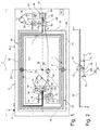
- the figure 1 represents a Laplace force magnetic field measuring device 2. More precisely, this device 2 is able to measure the amplitude of a component B Y of the magnetic field.
- the component B Y is represented by an arrow.
- the component B Y is parallel to the plane of the sheet and parallel to a Y axis of an orthogonal coordinate system X, Y, Z.
- the X and Y axes are horizontal and the Z axis is vertical.
- the terms “above”, “below”, “above” and “below” are defined relative to the direction Z.
- the device 2 comprises a substrate 6 which extends essentially in a horizontal plane called "Plan of the substrate".
- the dimensions of this substrate 6 are less than 1 mm 2 .
- its length is less than 1 mm or 500 ⁇ m
- its width is less than 500 microns or 300 microns.
- the substrate 6 is made of a machinable material by microelectronic techniques, that is to say the same techniques as those used for realize electronic components such as transistors.
- the substrate 6 is a semiconductor substrate such as silicon.
- the device comprises a rigid frame 10 suspended above the substrate 6.
- suspended means an element mechanically isolated from the substrate 6, in the Z direction, by a recess in which is evacuated or is filled with a gas.
- the element is then able to move relative to the substrate 6.
- the frame 10 is able to move in rotation about an axis 12 of rotation.
- the axis 12 is parallel to the direction X.
- the frame 10 extends essentially in a plane, called the plane of the frame.
- the frame 10 has a substantially rectangular shape.
- the frame 10 comprises a central through recess 14. On either side of the recess 14, in the X direction, the frame 10 comprises rigid arms 18 and 19. Similarly, on both sides of the recess 14, in the Y direction, the frame 10 has rigid legs 20 and 21. The arms 18 and 19 are parallel to the Y direction, while the legs 20 and 21 are parallel to the direction X. The ends of the legs 20 and 21 are fixed, without any degree of freedom, on one side, the arm 18 and, on the other side, the arm 19.
- the arm 19 is the symmetrical arm 18 relative to a vertical plane 23. Thus, only the arm 18 is described in more detail.
- the length Lo 18 of the arm 18 in the Y direction is typically less than 2 mm or 500 ⁇ m and, preferably, greater than 50 or 100 ⁇ m.
- the width 18 of the arm 18 in the X direction is less than Lo 18/2 or Lo 18/5 .
- the thickness of the arm 18 is equal to the thickness e CR of the frame 10.
- the thickness e CR is the average thickness of the frame 10 in the direction Z. For example, this thickness is strictly less than the width 18 / 2.
- the thickness e CR is less than 10 or 30 ⁇ m and, preferably, greater than 2 or 5 ⁇ m.
- the leg 21 is the symmetrical leg 20 relative to a vertical plane passing through the axis 12. This vertical plane is also a plane of symmetry for the arms 18 and 19.
- the length Lo 20 of the leg 20, in the direction X is typically less than 2 millimeters or 500 microns. This length Lo 20 is also preferably greater than 50 or 100 ⁇ m.
- the width 20 of the leg 20, in the Y direction is less than Lo 20/2 or Lo 20/5 .
- the thickness of the leg 20 is equal to the thickness e CR of the frame 10.
- the frame 10 is made of rigid materials, that is to say materials whose Young's model at 25 ° Celsius is greater than 20 GPa or 50 GPa or 100 GPa.
- the frame 10 is made of a semiconductor material such as silicon.
- the frame 10 also comprises two rigid lateral branches 24 and 26. These branches 24 and 26 form lateral projections from, respectively, the arms 18 and 19.
- the branch 24 extends along the axis 12 from the arm 18 towards the inside of the recess 14.
- the branch 26 extends along the axis 12 from the arm 19 away from the frame 10.
- the branches 24 and 26 form only one only block of material with, respectively, arms 18 and 19.
- the width 24 of the branch 24, in the direction Y, is here equal to the width 18 of the arm 18.
- the length Lo 24 of the branch 24, in the direction X, is less than or equal to Lo 20/2 or at Lo 20/3 .
- the thickness of the branch 24 is equal to the thickness e CR of the frame 10. This branch 24 is thus traversed from side-to-side by the axis 12.
- the branch 24 has a notch 28 dug in the direction Y.
- This notch 28 ends with a vertical bottom parallel to the axis 12 and located near this axis 12.
- the shortest distance between this vertical bottom and the The axis 12 is less than the width La24 / 3 and, preferably, less than La24 / 5 or La24 / 10.
- the shortest distance is less than 5 or 10 ⁇ m.
- this distance is zero.
- the notch 28 is entirely located on one side of the vertical plane passing through the axis 12.
- the branch 26 is identical to the branch 24 except that the notch 28 is replaced by a notch 30.
- the notch 30 is identical to the notch 28 but entirely located on the other side of the vertical plane passing through the axis 12 .
- the frame 10 is said to be “rigid”.
- rigid is meant the fact that its cross-section and the material in which it is made have been chosen so that its flexural stiffness, at a point of the leg 20 or 21 where s' applies the Laplace force to be measured, in the direction of application of this Laplace force, is at least two times greater and, preferably at least ten or a hundred times greater, the stiffness in compression of the suspended beam or beams which also attach this frame to the substrate 6.
- These suspended beams are described below.
- the bending stiffness is for example measured or calculated by replacing the torsion bar or bars by a corresponding anchor of infinite stiffness and having no degree of freedom. The torsion bars are described later.
- the direction of application of the Laplace force is parallel to the direction Z.
- the device 2 also comprises an electrical conductor 32 deposited, without any degree of freedom, on the upper face of the frame 10.
- This conductor 32 wraps around a vertical axis 34 perpendicular to the plane of the frame 10 and intersecting the axis 12
- the axis 34 is substantially at the center of the rectangular recess 14.
- this axis 34 is represented by a point in the middle of a circle.
- the flow direction of the current in the conductor 32 is represented by arrows i.
- the Laplace force is exerted perpendicularly to the plane of the substrate in one direction on the leg 20 and in the opposite direction on the leg 21.
- the Laplace force rotates the frame 10 about its axis 12 rotation. Therefore, the angular displacement of the frame 10 represents the intensity of the Laplace force and therefore of the component B y of the magnetic field to be measured.
- each hinge is constituted by a torsion bar.
- the bar 38 is suspended above the substrate 6. It extends along the axis 12 from the distal end of the branch 24 to a protrusion 40 anchor.
- the projection 40 is fixed without any degree of freedom on the substrate 6.
- a torsion bar designates a bar shaped to deform substantially in torsion around an axis of rotation when using the device 2.
- the axis of rotation is the axis 12.
- the bar 38 is shaped so that its bending stiffness in directions orthogonal to the axis of rotation is at least five or ten times greater than its torsional stiffness measured or calculated at same point.
- the width 38 of the bar 38, in the Y direction is at least two or five times smaller than the width 24 of the branch 24.
- the thickness e 38 of the bar 38 is equal to the thickness e CR to facilitate the passage of an electric track.
- the bar 38 also electrically connects one of the ends of the conductor 32 to a fixed pad 42 of electrical connection.
- the stud 42 is located on an upper end of the projection 40 and electrically insulated from this projection by a layer 44 of electrically insulating material.
- the bar 38 has on its upper part an electrical track 46 which passes through it from side to side. An insulating layer is disposed between this electrical track 46 and the semiconductor portion of the bar 38.
- the bar 39 extends along the axis 12 from the distal end of the branch 26 to a protrusion 50 anchor.
- the bar 39 is identical to the bar 38.
- the stud, the layer of insulating material and the corresponding conductive track, respectively, the pad 42, the layer 44 and the track 46 are, respectively, references 52, 54 and 56.
- the pads 42 and 52 are electrically connected via wire links to a source 58 of current.
- the source 58 is a source of alternating current.
- the thickness of the beam 64 is at least two, five or ten times smaller than the thickness of the branch 24 so as to concentrate the stress exerted by the branch 24 inside a reduced surface which increases the sensitivity of the device 2. This also makes it possible to decrease its stiffness in traction-compression.
- the width and, optionally, the length of the beam 64 are, for example, less than 10 or 5 ⁇ m.
- the beam 64 extends parallel to the direction Y.
- the end 66 is located above or below a horizontal plane passing through the axis 12.
- the end 66 is located below this horizontal plane ( Figure 2 ) and the beam 64 extends entirely in this horizontal plane, that is to say that its upper face is spaced from this horizontal plane by a non-zero distance.
- the arm 18 extending in the horizontal plane passing through the axis 12 is shown to improve the readability of this figure.
- the end 66 is as close as possible to the axis 12 to benefit the maximum of an amplification effect and a force on the beam in pure tension / compression from the Laplace force caused by the arm 18
- the distance d p ( Figure 2 ) the shorter between the end 66 and the axis 12 is less than e CR / 2 and, preferably, e CR / 3 or e CR / 5.
- this distance is less than 5 or 10 ⁇ m.
- the sensor 60 also comprises two electrical pads 72 and 74 and an ohmmeter 76.
- the pads 72 and 74 are directly electrically connected, respectively, to the ends 66 and 68 of the beam 64.
- the fact is that the connection does not pass through the beam 64 or the ohmmeter 76.
- ohmmeter means here any type of device capable of measuring a variation of resistance, directly or indirectly.
- ohmmeter it will be possible, for example, to use a voltage measurement across a Wheatstone bridge.
- the sensors 60 and 62 are integrated for this purpose in a Wheatstone half-bridge.
- the stud 74 is electrically connected to the end 66 via the torsion bar 38.
- the ohmmeter 76 is electrically connected to the pads 72 and 74 via wire links. This ohmmeter 76 measures the resistance variation of the beam 64 in response to the stress exerted on it by the lever 18 and generates a measurement signal representative of the measured resistance.
- the other sensor 62 is identical to the sensor 60 except that it measures a displacement of the same amplitude as the sensor 60 but of opposite direction because its suspended beam is located on the other side of the vertical plane passing through the axis 12.
- the beam, the roughness, the electrical pads and the ohmmeter of the sensor 60 corresponding to the beam 64, the roughness 70, the pads 72, 74 and the ohmmeter 76 respectively bear the references 80, 82 , 84, 86 and 90.
- the sensors 60 and 62 are connected to an electronic processing unit 94.
- the unit 94 is programmed to calculate the amplitude of the component B Y as a function of the measurement signals delivered by the sensors 60 and 62. To simplify the illustration, the connection between the unit 94 is the sensors is not represent.
- the mechanical resonance frequency f R of the device 2 is essentially fixed by the frame 10, the torsion bars 38, 39 and the beams 64, 80.
- the dimensions of the frame 10, the torsion bars 38, 39 and the beams 64, 80 are chosen so that the frequency f R is greater than 1 kHz and, preferably, greater than 10 kHz. Thanks to the architecture of the device 2, it is possible to modify the dimensions of one of these elements of the device to set this frequency f R without modifying the other elements, which greatly facilitates the mechanical optimization of the device 2.
- the figure 2 allows to better understand why the Laplace force is amplified by the lever effect in the device 2.
- the Laplace force exerts itself at the end of the arms 18 and 19 in opposite directions on both sides of the axis of rotation 12. This rotates the branch 24 about the axis 12. Since the end 66 of the beam 64 secured to the branch 24 is located below the axis 12, the rotation of the branch 24 exerts, in the case shown, mainly a tensile force F t on the beam 64.
- the torsion bar 38 forms a fixed axis of rotation relative to the substrate 6 and that the distance d between the point of application of the force F and the axis 12 is several times greater than the distance d p between the end 66 and the axis 12, the force F t is several times greater than the force of Laplace F because of the leverage effect. This increases the sensitivity of the device 2.
- the operation of the device 2 is as follows.
- the source 58 generates an alternating current at the frequency f A equal, advantageously, to the resonant frequency f R.
- the force of Laplace is exerted on the conductor 32 sometimes in the direction Z, sometimes in the opposite direction.
- This excites device 2 at this frequency f A.
- the frame 10 then oscillates about the axis 12 at the frequency f A.
- the angular amplitude of these oscillations is representative of the Lorentz force which is exerted and therefore the amplitude of the component B Y.
- the sensors 60 and 62 generate measurement signals representative of the amplitude of angular displacement of the frame 10 and transmit these signals to the unit 94.
- the unit 94 calculates the amplitude of the component of the magnetic field B Y from these signals.
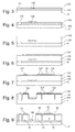
- the Figures 3 to 9 represent different successive stages of manufacture of the device 2.
- the Figures 3 to 9 are vertical sectional views of different elements of the device 2. These different elements have been juxtaposed in these views, even if they are not next to each other in the device 2. Thus, these views do not correspond to each other. not to a section of the device 2 according to a cutting plane but simply illustrate the manufacture of the various elements without taking into account their arrangement relative to each other in the device 2.
- the manufacturing begins with the supply of an SOI (Silicon-On-Insulator) substrate.
- This substrate comprises the substrate 6, a layer 120 ( Figure 3 ) of electrically insulating material such as silicon oxide and a layer 122 ( Figure 3 ) of silicon.
- the layers 120 and 122 respectively have thicknesses of 1 ⁇ m and 0.3 ⁇ m.
- the layer 122 is etched by photolithography so as to form a hole 124 and two holes 126 ( Figure 3 ).
- the hole 124 is used for producing an electrical contact pad with the substrate 6.
- the two holes 126 are used for producing the piezoresistive beam 64 of the sensor 60.
- an oxide layer 128 ( Figure 4 ) is deposited on the layer 122.
- the thickness of the layer 128 is 0.3 microns.
- the layer 128 is etched using a photo-lithographic process to leave only those parts of the layer 128 which fill and cover the two holes 126. This layer 128 is intended to cover and protect the beam of the sensor. constraint. During these etching steps, the oxide layer at the bottom of the hole 124 is also removed to leave the substrate 6 exposed to the outside.
- a layer 130 ( figure 5 ) of silicon is deposited on the layer 128.
- this layer 130 is deposited by epitaxial growth on the layer 122 and on the remains of the layer 128.
- This layer 130 forms a single layer with the layer 122 so that only the layer 130 has been shown.
- the thickness of the layer 130 is about 20 ⁇ m.
- a layer 132 ( figure 6 ) of electrically insulating material is then deposited on the layer 130. This layer 132 is then etched by photolithography at the locations where the formation of a direct electrical contact with the layer 130 is needed.
- the layer 132 is a 0.1 ⁇ m thick silicon nitride layer.
- a layer 134 ( figure 7 ) of electrically conductive material is then deposited on the layer 132.
- the layer 134 is a metal layer.
- This layer 134 is then etched to form the different pads and electrical tracks of the device 2.
- the layer 132 is etched ( figure 8 ) by photolithography.
- Layer 130 is also etched using the same resin mask and oxide layers 120 and 128 as a barrier layer.
- the layer 130 is etched using the DRIE (Deep Reactive Ion Etching) etching process.
- the oxide layers 120 and 128 are removed ( figure 9 ) to release the various moving parts of the device 2.
- the oxide layers are removed by wet HF etching and / or vapor phase.
- the figure 10 represents a device 150 identical to the device 2, except that the sensors 60 and 62 are, respectively, replaced by sensors 152 and 154 resonant strain strainers.
- the sensors 152 and 154 are identical except that they each measure a stress of the same amplitude as that measured by the other sensor but of opposite sign. Thus, only the sensor 152 is described in more detail with reference to the figure 11 .
- the sensor 152 comprises a beam 160 suspended above the substrate 6.
- An end 162 of this beam is anchored, without any degree of freedom, in the axis of the beam, to the branch 24 at the bottom of the notch 28.
- the opposite end 164 of this beam is anchored without any degree of freedom to the asperity 70.
- a movable central portion 166 of this beam is located between the ends 162 and 164. This movable part 166 is suspended above the substrate 6 in order to vibrate.
- the beam 160 is made of semiconductor material or conductor. Here, it is made of silicon. However, it is not necessary in this embodiment that it be made of piezoresistive material.
- the sensor 152 also comprises an actuating electrode 168 placed near the moving part 166 to exert on this mobile part an electrostatic force which attracts it periodically in the X direction.
- the electrode 168 is electrically connected via an electrical pad 170 to a terminal of an AC voltage source 172 having a DC component.
- the AC voltage is generated at a frequency controlled by the mechanical resonance frequency of the beam 160. To achieve this control, it is used that the vibration amplitude of the beam 160 is maximum when the beam vibrates at its resonant frequency .
- Another terminal of the source 172 is directly connected to the end 164 of the beam 160 via an electrical pad 174. Thus, the beam 160 vibrates at a frequency f 0 .
- the sensor 152 also comprises a measurement electrode 176 disposed opposite the mobile part 166 to form with the mobile part a capacitor whose capacitance varies as a function of the displacement of the mobile part 166.
- the electrode 176 is electrically connected to a terminal of a capacimeter 178 via an electrical pad 180.
- the other terminal of the capacitance meter 178 is connected to the pad 174.
- the capacitance meter 178 makes it possible to measure the amplitude and / or the frequency of the capacitor 178. vibration of the moving part 166.
- the resonance frequency f 0 varies as a function of the stress exerted by the branch 24 on the beam 160. The value of the frequency f 0 thus makes it possible to measure the amplitude of the angular deflection of the branch 24 and therefore the amplitude of the component B Y.
- the stud 42 is replaced by a stud 194 directly in electrical contact with the projection 40.
- the insulating layer 44 between the stud 194 and the projection 40 is omitted.
- the projection 40 is electrically connected to a projection 196 located outside the recess 14 via an electrical track 198.
- This track 198 is fixed without any degree of freedom on the substrate 6.
- the track 198 passes below the leg 20 of the frame 10 to join the projection 196.
- the leg 20 is suspended above the track 198.
- the pad 192 is deposited on the upper end of the projection 196.
- the sensor 60 is placed opposite the sensor 62.
- the beam 64 is symmetrical to the beam 80 with respect to a vertical plane passing through the axis 12.
- the branch 26 is replaced by a branch 200.
- the branch 200 is identical to the branch 26 except that it further comprises a notch 202 symmetrical with the notch 30 with respect to the vertical plane containing the axis 12.
- the end of the beam 64 is fixed to the bottom of the notch 202. Under these conditions, as before, the sensor 60 measures an angular deflection of the same amplitude as the sensor 62 but of opposite sign.
- the Figures 13 to 19 represent the different manufacturing steps of the device 190. These steps are identical to those described with reference to the Figures 3 to 9 for all the elements of the device except for the realization of the track 198 and the pads 192 and 196. More specifically, the steps implemented to obtain the different states of manufacture represented successively on the Figures 13 to 19 are identical to those described with reference, respectively, to Figures 3 to 9 except that an additional piece 210 of the oxide layer 128 (see figure 14 ) is left to preserve a piece of the layer 122 passing under the frame 10. As shown in FIG. figure 18 this piece 210 serves as an etch stop layer during the etching of the layer 130. Then, this piece 210 is removed together with the remainder of the layer 128 to release the various moving parts ( figure 19 ). We then obtain the track 198 which passes under the frame 10.
- the metal layer 134 is directly deposited on the layer 130 and etched to delimit the pads 194 and 196 ( figure 17 ).
- the figure 20 represents a device 220 capable of measuring both the B y and B x components of the magnetic field while using only one conductor forming a coil with several turns.
- This device 220 includes an inner frame 222 identical to the frame 10, except that the branches 24 and 26 are replaced by, respectively, branches 224 and 226.
- the branches 224 and 226 are located inside the recess 14.
- the branch 224 extends along the axis 12 of rotation of the frame 222.
- the branch 224 is shaped to be torsionally rigid around the axis 12 and flexible in flexion in the Z direction.
- the branch 224 is identical to the branch 24 but also comprises a hinge 228 rigid in torsion and flexibly flexible in the direction Z.
- the hinge 228 is made by successively combining a thinning 228A followed by a rectangular recess 228B. Thinning 228A locally reduces the width of branch 224 in the Y direction. The width of this thinning 228A, in the Y direction, is denoted La 228A . Thinning 228A is centered on the axis 12 of rotation.
- the recess 228B is a rectangular recess passing right through the branch 224 in the direction Z.
- the width of this recess, denoted La 228B , in the direction Y is strictly greater than the width La 228A .
- Thinning 228A is more torsionally stiff than the torsion bar 38. For this, for example, its width The 228A is at least twice the width The 38 or its length Lo 228A in the X direction is at least two times smaller than the length Lo 38 . Under these conditions, the hinge 228 is much more rigid in torsion than the bar 38. Thus, during a rotational movement of the branch 224 is almost exclusively the torsion bar 38 which is deformed. The hinge 228 reduces the stiffness of the branch 224 to the flexion in the Z direction. Therefore, this allows the frame 222 to move in rotation also about a horizontal axis 246 perpendicular to the axis 12.
- the end of the branch 224 is mechanically connected via the bar 38 to the projection 40.
- the projection 40 includes the pad 42 of electrical connection of the electrical conductor 32 to the source 58 of alternating current. In this figure and the following, the source 58 has not been shown.
- the branch 226 is structurally similar to the branch 224 except that it mechanically connects the arm 19 to the substrate 6 and not the arm 18 to the substrate 6.
- the articulation and the notch of the branch 226 bear, respectively, the references 242. and 244.
- the branch 226 is the symmetrical branch 224 with respect to a vertical plane passing through the axis 246 except that its notch 244 is located on the other side of the vertical plane passing through the axis 12.
- a torsion bar 248 mechanically connects the end of the branch 226 to the projection 40.
- the bar 248 is symmetrical with the bar 38 with respect to the vertical plane passing through the axis 246.
- the beam 80 of the sensor 62 is mechanically connected to the bottom of the slot 244 as described with reference to FIGS. Figures 1 and 2 .
- the branch 226 does not have a conductive track for connecting the other end of the conductor 32 to the source 58 of current.
- the device 220 also comprises a suspended outer rigid frame 252 rotatably mounted about the axis 246.
- This frame 252 holds the frame 222 suspended above the substrate 6.
- the frame 252 has two parallel arms 254 and 255 in the X direction and two parallel legs 258 and 259 in the direction Y. These arms and legs delimit an inner recess 262 through and rectangular.
- Each rigid arm 254, 255 has a rigid branch, respectively, 264 and 266.
- These branches 264 and 266 extend along the axis 246 away from each frame 252.
- the distal ends of these branches 264 and 266 are mechanically connected to protrusions, respectively 268 and 269, via torsion bars, respectively 272 and 274.
- the projections 268, 269 are fixed without any degree of freedom on the substrate 6;
- torsion bars 272 and 274 make it possible, like the torsion bars 38 and 39, to keep the frame 252 suspended above the substrate 6 while essentially allowing only a rotational movement of the frame 252 about the axis 246. .
- the branch 266 is arranged as the branch 200. It therefore includes two notches 30 and 202 vis-à-vis. Sensors 276 and 278 are provided for measuring the angular displacement of the frame 252 about the axis 246.
- the sensors 276 and 278 are identical, respectively, to the sensors 60 and 62. They are arranged in facing relation to each other. one of the other as described with reference to figure 12 .
- the frame 252 is mechanically connected to the frame 222 by torsion bars 280 and 282 extending along the axis 12.
- the torsion bar 280 mechanically directly connects the middle of the leg 258 to the middle of the arm 18.
- the bar torsion 282 directly mechanically connects the middle of the leg 259 in the middle of the arm 19.
- the torsion bars 280 and 282 make it possible to hold the frame 222 suspended above the substrate 6 while leaving this frame 222 free to move in rotation about the axis 12.
- the structure of the frame 252 and the torsion bars 280 and 282 is designed to amplify the Laplace forces Fx through a lever effect of the arms 254 and 255.
- the frame 252 and the bars 280, 282 are made as described. with reference to frame 10 and bars 38 and 39.
- An electrical track 286 connects the other end of the conductor 32, not directly connected to the pad 42, to a connection pad 288 disposed on the upper end of the projection 269.
- the stud 288 is electrically insulated from the projection 269 by a layer 292 of electrically insulating material.
- the track 286 is deposited successively on the torsion bar 282, on the leg 259, on the arm 255, on the branch 266 and on the torsion bar 274 before reaching the stud 288.
- the leg 258 and the arm 254 are devoid of electrical conductor.
- the displacement in rotation about the axis 246 of the frame 252 is caused by the Laplace forces Fx acting on the conductor 2 when it is traversed by a current in the presence of the component B x .
- a single electrical conductor, forming a coil is used to measure both the components B x and B y of the magnetic field. This significantly reduces the power consumption of the device 220.
- the device 220 also comprises an electronic processing unit 300 connected to the various sensors of the device 220 for transforming the signals of these sensors into a measurement of the intensity of the components B x and B y .
- the operation of the device 220 is similar to that of the device 2 and will not be described in more detail.
- the device 220 amplifies, thanks to a lever effect, both the Laplace forces F y and F x .
- the figure 21 represents a device 310 identical to the device 2 except that the frame 252 is replaced by a rigid frame 312.
- the frame 312 is identical to the frame 252 except that the arm 254 is omitted and the length of the legs 258 and 259 is shortened. Branch 264, torsion bar 272 and protrusion 268 are also omitted.
- This device 310 functions as the device 220.
- the magnetic field measuring device may comprise one or more measurement axes.
- the measuring device can be single-axis or multi-axis.
- each of the devices described above can be enclosed in a box inside which the vacuum is made. This allows in particular to increase the quality factor of the mechanical system. However, depending on the applications and the desired sensitivity, this is not necessarily necessary.
- the electrical conductor may form a single turn or, on the contrary, several complete turns.
- the current flowing in the electrical conductor is not necessarily alternative. Alternatively, it is a non-sinusoidally varying current as a function of time or a continuous current that never changes sign.
- the devices has only one sensor for measuring the angular movement of the lever.
- the ohmmeter can be replaced by any means of measuring an electrical resistance such as a Wheatstone bridge.
- a single electrode can be used both to resonate the beam and to measure the vibration frequency of that beam.
- the capacimeter may be replaced by any means for measuring the vibration frequency of the beam of the resonant gage.
- the axes 12 and 246 are not perpendicular to each other.
- these two axes are not parallel to each other either.
- the outer rigid frame 252 may comprise an electrical conductor wound around its central recess 262. In this case, preferably, this conductor is connected in series with the electrical conductor 32 and replaces the track 286.
- the electrical conductor 32 can be fed via the torsion bar 248 even in the case where it comprises the outer frame 252. In this case, the electrical track 286 is omitted.
- the sensor 152 with a resonant gage described next to the figure 11 may be used in all the other embodiments described above in place of a strain gage sensor.
- a torsion bar can be made as described in the patent application filed in 2011 under the number FR1161487 .
- a hinge can also be made without using a torsion bar.
- two horizontal slats flexible in the direction Z and disposed vis-a-vis on either side of the axis of rotation can be used to achieve a hinge.
- the thickness e 38 of the torsion bar 38 is at least two or five or ten times smaller, in the Z direction, than the thickness e CR of the branch 24.
- the bottom of the notches is contained in the plane perpendicular to the plane of the frame and passing through the axis of rotation of this frame.
- the mobile frame can be suspended above the substrate by means of a single hinge.
- Weights can be added to the moving frame so as to move its center of gravity away from the axis 12. By doing this, the moving frame is also made sensitive to accelerations. Then, the processing unit is programmed to eliminate from the measurement signal all the frequency components less than, for example, 1000 Hz. The thus filtered signal is then used to determine the intensity of the component of the measured magnetic field. The same signal can also be filtered in parallel to eliminate all frequency components above 1000 Hz. This filtered signal is then used to measure the acceleration undergone by the moving frame.
- the weight can be a protrusion of material in the Y direction, on one of the legs of the frame. In this case, the frame is made sensitive to accelerations parallel to the direction Z. The weight can also be a protrusion of material located in the plane perpendicular to the plane of the frame passing through the axis 12. In this case, the frame is made responsive to accelerations in direction Y.
- the recess in the center of the frame may be omitted.
- the beam of the stress sensor extends parallel to the direction Z between one end anchored in the substrate 6 and another end directly anchored in the lower face of one of the arms of the movable frame.
Landscapes
- Physics & Mathematics (AREA)
- General Physics & Mathematics (AREA)
- Condensed Matter Physics & Semiconductors (AREA)
- Gyroscopes (AREA)
- Pressure Sensors (AREA)
- Measuring Magnetic Variables (AREA)
Claims (14)
- Vorrichtung zur Messung eines Magnetfeldes mit Laplace-Kraft, wobei diese Vorrichtung umfasst:- ein Substrat (6), das sich im Wesentlichen in einer Ebene erstreckt, "Substratebene" genannt,- einen ersten starren Rahmen (10; 222), der sich im Wesentlichen in einer Ebene erstreckt, "Ebene des ersten Rahmens" genannt, und der über dem Substrat aufgehängt ist, wobei dieser erste Rahmen in Bezug zu dem Substrat in Drehung um eine erste Achse (12) mit einer Drehung parallel zu der Ebene des Substrats verschiebbar ist, wobei der erste starre Rahmen eine durchgehende zentrale Ausnehmung (14) umfasst,- einen elektrischen Leiter (32), der ohne Freiheitsgrad auf dem ersten starren Rahmen befestigt ist und ein erstes und ein zweites Ende umfasst, wobei dieser Leiter zwischen seinem ersten und seinem zweiten Ende um eine Wickelachse (34) senkrecht zu der Ebene des ersten Rahmens gewickelt ist,- mindestens ein erstes Scharnier (38), das den ersten starren Rahmen mechanisch an das Substrat anschließt, wobei dieses Scharnier eine erste elektrische Spur (46) umfasst, die das erste Ende des elektrischen Leiters an ein erstes Kontaktstück (42; 192), das mit dem Substrat verbunden ist, anschließt;- ein zweites Scharnier (39; 248), das mechanisch an den ersten starren Rahmen angeschlossen ist und eine zweite elektrische Spur (46) umfasst, die das zweite Ende des elektrischen Leiters an ein zweites Kontaktstück (52), das mit dem Substrat verbunden ist, anschließt, und- mindestens einen ersten Sensor (60, 62; 152, 154), der geeignet ist, eine physikalische Größe, die für die Amplitude des Winkelausschlags des ersten starren Rahmens um seine Drehachse repräsentativ ist, zu messen,dadurch gekennzeichnet, dass:- das erste Scharnier (38) und seine erste Spur (46) im Inneren der zentralen Ausnehmung (14) des ersten starren Rahmens angeordnet sind, und- das zweite Scharnier (39; 248) und seine zweite Spur (46) außerhalb der zentralen Ausnehmung (14) des ersten starren Rahmens angeordnet sind.
- Vorrichtung nach Anspruch 1, bei der der erste Sensor (60, 62; 152, 154) ein Spannungssensor ist, und dieser Sensor einen Träger (64, 80; 160) umfasst, dessen erstes Ende direkt in dem ersten starren Rahmen verankert ist, und dessen zweites Ende ohne Freiheitsgrad auf dem Substrat verankert ist, wobei das erste Ende in dem ersten starren Rahmen in einem Abstand dp ungleich Null zu der ersten Drehachse verankert ist, wobei dieser Abstand dp mindestens zweimal kleiner als die Dicke des ersten Rahmens ist, und die Dicke dieses Trägers mindestens zweimal kleiner als die Dicke des ersten starren Rahmens ist.
- Vorrichtung nach Anspruch 2, bei der der Träger zur Gänze unter einer Ebene parallel zur Ebene des Substrats und durch die Drehachse verlaufend angeordnet ist.
- Vorrichtung nach einem der vorhergehenden Ansprüche, bei der der Schwerpunkt des ersten starren Rahmens (10; 222) in einer Ebene senkrecht zur des ersten Rahmens, die die erste Drehachse enthält, enthalten ist.
- Vorrichtung nach einem der Ansprüche 2 bis 4, bei der der erste starre Rahmen mindestens einen starren Seitenschenkel (24, 26; 200; 224, 226) umfasst, der sich entlang der ersten Drehachse erstreckt, und der Träger (64, 80; 160) ein über dem Substrat hängender Träger ist, wobei sich dieser Träger senkrecht zur ersten Drehachse im Wesentlichen in einer Ebene parallel zur Ebene des Substrats erstreckt, und wobei sein erstes Ende:- genau über oder genau unter einer Ebene angeordnet ist, die durch die erste Drehachse verläuft und zur Ebene des Substrats parallel ist, und- direkt auf dem Seitenschenkel befestigt ist.
- Vorrichtung nach Anspruch 5, bei der der Seitenschenkel eine Kerbe (28, 30; 30, 202; 28, 244) umfasst, die sich senkrecht zur ersten Drehachse bis zu einem Boden erstreckt, und das erste Ende des Trägers direkt ohne Freiheitsgrad auf diesem Boden befestigt ist.
- Vorrichtung nach einem der vorhergehenden Ansprüche, bei der der erste starre Rahmen einen ersten und einen zweiten starren Arm (18, 19) umfasst, die parallel sind und sich beiderseits der zentralen Ausnehmung (14) befinden, die durch den ersten starren Rahmen hindurchgeht, und das zweite Scharnier (39) mechanisch den ersten starren Rahmen an das Substrat anschließt, wobei die ersten und zweiten Scharniere mechanisch direkt an den ersten bzw. zweiten Arm angeschlossen sind.
- Vorrichtung nach einem der vorhergehenden Ansprüche, bei der das erste Kontaktstück (192) außerhalb des ersten starren Rahmens angeordnet ist, und die Vorrichtung eine elektrische Spur (198) umfasst, die unter dem ersten starren Rahmen verläuft und die erste elektrische Spur (46) des ersten Scharniers (38) elektrisch mit diesem Kontaktstück (192) verbindet, das mit dem Substrat verbunden ist, das sich außerhalb des starren Rahmens befindet.
- Vorrichtung nach einem der vorhergehenden Ansprüche, wobei die Vorrichtung umfasst:- einen zweiten starren Rahmen (252; 312), der sich im Wesentlichen in einer Ebene erstreckt und über dem Substrat hängt, wobei dieser zweite Rahmen in Bezug zu dem Substrat in Drehung um eine zweite Drehachse (246) parallel zur Ebene des Substrats und nicht parallel zur ersten Drehachse (12) verschiebbar ist, wobei dieser zweite starre Rahmen eine zentrale Ausnehmung (262) umfasst, in der der erste starre Rahmen aufgenommen ist,- mindestens ein drittes Scharnier (272, 274), das mechanisch den zweiten starren Rahmen an das Substrat anschließt,- mindestens einen zweiten Sensor (276, 278), der geeignet ist, eine physikalische Größe, die für die Amplitude des Winkelausschlags des zweiten starren Rahmens um die zweite Drehachse repräsentativ ist, zu messen, und- wobei das zweite Scharnier (282) über dem Substrat hängt und einerseits auf dem ersten starren Rahmen und auf einer gegenüberliegenden Seite auf dem zweiten starren Rahmen befestigt ist, wobei dieses zweite hängende Scharnier derart ausgeführt ist, dass es die Drehung des ersten starren Rahmens um die erste Drehachse gestattet und diesen ersten starren Rahmen über dem Substrat hängend hält.
- Vorrichtung nach einem der vorhergehenden Ansprüche, bei der die Wickelachse durch die zentrale Ausnehmung hindurchgeht.
- Vorrichtung nach einem der vorhergehenden Ansprüche, bei der jedes Scharnier, das die Drehung eines starren Rahmens um seine Drehachse ermöglicht, einen Torsionsstab umfasst, der sich entlang dieser Drehachse erstreckt, wobei dieser Torsionsstab derart ausgeführt ist, dass er sich im Wesentlichen bei der Drehung dieses starren Rahmens in Torsion verformt.
- Vorrichtung nach einem der vorhergehenden Ansprüche, bei der sich der elektrische Leiter (32) mehrmals um die erste Wickelachse wickelt, um eine Spule mit mehreren Windungen zu bilden.
- Vorrichtung nach Anspruch 2, bei der der Träger (64, 80) des Sensors aus einem piezoresistiven Material hergestellt ist, und der Sensor Mittel umfasst, die geeignet sind, eine physikalische Größe zu messen, die für die Variation des Widerstands des Trägers als Reaktion auf die Drehung des starren Rahmens repräsentativ ist.
- Vorrichtung nach Anspruch 2, bei der der Sensor umfasst:- eine Elektrode (168), die geeignet ist, den Träger (160) vibrieren zu lassen,- eine weitere Elektrode (176) oder dieselbe Elektrode, um die Vibration des Trägers zu messen,- Mittel (178), die geeignet sind, eine physikalische Größe zu messen, die für die Vibrationsfrequenz des Trägers repräsentativ ist,- eine Versorgungsquelle der Elektrode, die geeignet ist, die Vibrationsfrequenz des Trägers auf die mechanische Resonanzfrequenz dieses Trägers einzustellen.
Applications Claiming Priority (2)
| Application Number | Priority Date | Filing Date | Title |
|---|---|---|---|
| FR1258056A FR2995086B1 (fr) | 2012-08-29 | 2012-08-29 | Dispositif de mesure d'un champ magnetique a force de laplace |
| PCT/EP2013/067857 WO2014033194A1 (fr) | 2012-08-29 | 2013-08-29 | Dispositif de mesure de champ magnetique a force de laplace |
Publications (2)
| Publication Number | Publication Date |
|---|---|
| EP2890992A1 EP2890992A1 (de) | 2015-07-08 |
| EP2890992B1 true EP2890992B1 (de) | 2016-09-21 |
Family
ID=47739370
Family Applications (1)
| Application Number | Title | Priority Date | Filing Date |
|---|---|---|---|
| EP13756434.0A Not-in-force EP2890992B1 (de) | 2012-08-29 | 2013-08-29 | Vorrichtung zur messung von magnetfeldern mit laplace-kraft |
Country Status (5)
| Country | Link |
|---|---|
| US (1) | US9417097B2 (de) |
| EP (1) | EP2890992B1 (de) |
| JP (1) | JP5857161B2 (de) |
| FR (1) | FR2995086B1 (de) |
| WO (1) | WO2014033194A1 (de) |
Families Citing this family (4)
| Publication number | Priority date | Publication date | Assignee | Title |
|---|---|---|---|---|
| FR2983844B1 (fr) * | 2011-12-12 | 2014-08-08 | Commissariat Energie Atomique | Liaison mecanique formant pivot pour structures mecaniques mems et nems |
| TWI526703B (zh) * | 2014-09-18 | 2016-03-21 | 碩英股份有限公司 | 共振型磁力計 |
| US11198050B1 (en) | 2016-09-16 | 2021-12-14 | Robert Moran | Speed tracker |
| WO2018053310A1 (en) | 2016-09-16 | 2018-03-22 | Robert Moran | Speed tracker |
Family Cites Families (11)
| Publication number | Priority date | Publication date | Assignee | Title |
|---|---|---|---|---|
| FR1161487A (fr) | 1956-09-25 | 1958-09-01 | Semi-remorque universelle | |
| US5818227A (en) * | 1996-02-22 | 1998-10-06 | Analog Devices, Inc. | Rotatable micromachined device for sensing magnetic fields |
| DE19827056A1 (de) * | 1998-06-18 | 1999-12-23 | Bosch Gmbh Robert | Mikromechanischer Magnetfeldsensor |
| US6664786B2 (en) * | 2001-07-30 | 2003-12-16 | Rockwell Automation Technologies, Inc. | Magnetic field sensor using microelectromechanical system |
| US7221144B2 (en) * | 2004-06-07 | 2007-05-22 | General Electric Company | Micro-electromechanical system (MEMS) based current and magnetic field sensor having improved sensitivities |
| US7642692B1 (en) * | 2005-09-15 | 2010-01-05 | The United States Of America As Represented By The Secretary Of The Army | PZT MEMS resonant Lorentz force magnetometer |
| JP5055030B2 (ja) * | 2007-06-13 | 2012-10-24 | 株式会社リコー | 磁気センシング装置 |
| JP2009074948A (ja) * | 2007-09-21 | 2009-04-09 | Canon Inc | 揺動体装置、及びそれを用いた電位測定装置、画像形成装置 |
| JP5184309B2 (ja) * | 2007-11-21 | 2013-04-17 | 株式会社フジクラ | 磁界検出素子 |
| FR2941534B1 (fr) * | 2009-01-26 | 2011-12-23 | Commissariat Energie Atomique | Capteur de champ magnetique a jauge de contrainte suspendue |
| FR2983844B1 (fr) | 2011-12-12 | 2014-08-08 | Commissariat Energie Atomique | Liaison mecanique formant pivot pour structures mecaniques mems et nems |
-
2012
- 2012-08-29 FR FR1258056A patent/FR2995086B1/fr not_active Expired - Fee Related
-
2013
- 2013-08-29 US US14/423,831 patent/US9417097B2/en not_active Expired - Fee Related
- 2013-08-29 JP JP2015529015A patent/JP5857161B2/ja not_active Expired - Fee Related
- 2013-08-29 WO PCT/EP2013/067857 patent/WO2014033194A1/fr not_active Ceased
- 2013-08-29 EP EP13756434.0A patent/EP2890992B1/de not_active Not-in-force
Also Published As
| Publication number | Publication date |
|---|---|
| FR2995086B1 (fr) | 2014-09-12 |
| JP5857161B2 (ja) | 2016-02-10 |
| US9417097B2 (en) | 2016-08-16 |
| US20150211891A1 (en) | 2015-07-30 |
| JP2015531871A (ja) | 2015-11-05 |
| WO2014033194A1 (fr) | 2014-03-06 |
| FR2995086A1 (fr) | 2014-03-07 |
| EP2890992A1 (de) | 2015-07-08 |
Similar Documents
| Publication | Publication Date | Title |
|---|---|---|
| EP2367015B1 (de) | Rauscharmer kraftsensor | |
| EP2796884B1 (de) | Mikroelektromechanische und/oder nanoelektromechanische Struktur mit einstellbarer Qualitätsfaktor | |
| EP2617129B1 (de) | Vorrichtung mit freihängendem träger und piezoresistive vorrichtung zur verlagerungserkennung | |
| EP2008965B1 (de) | Resonanzvorrichtung mit piezoelektrischer Erfassung für den Einsatz in Oberflächentechnologien | |
| EP2211185B1 (de) | Trägheitssensor oder Resonanzsensor in der Oberflächentechnologie zur Erkennung von Abweichungen mit Hilfe eines Dehnungsmessers | |
| EP2065713B1 (de) | Erfassungsvorrichtung mittels aufgehängtem Dehnungsmesser mit piezoelektrischem Widerstand, der eine Dehnungsverstärkungszelle umfasst | |
| EP2592429B1 (de) | Vektorieller Magnetfeldsensor | |
| EP2405238B1 (de) | Trägheitssensor zum Erfassen der Drehbewegungen einer oszillierenden Scheibe | |
| EP2617130B1 (de) | Resonanter piezoresistiver detektor mit einem an das trägerelement des detektors elastisch angeschlossenen resonator und verfahren zur herstellung dieses detektors | |
| FR2941534A1 (fr) | Capteur de champ magnetique a jauge de contrainte suspendue | |
| EP2668510B1 (de) | Vorrichtung zum messen der temperatur eines vibrierenden balkens und deren verwendung zur verbesserung der messgenauigkeit eines sensors mit vibrierendem balken | |
| FR2941525A1 (fr) | Gyrometre en technologie de surface, a detection hors plan par jauge de contrainte. | |
| EP2890992B1 (de) | Vorrichtung zur messung von magnetfeldern mit laplace-kraft | |
| EP1558896A1 (de) | Mikrobearbeiteter kreiselratensensor mit detektion in der bearbeiteten plattenebene | |
| EP2815210A1 (de) | Kompakte vorrichtung zur erfassung mindestens einer beschleunigung und einer drehzahl | |
| WO2012034949A1 (fr) | Dispositif resonant a actionnement dans le plan, et procede de fabrication du dispositif | |
| EP1570275B1 (de) | Beschleunigungssensor mit vibrierenden schwingbalken | |
| FR2995995A1 (fr) | Capteur de pression a base de nanojauges couplees a un resonateur | |
| FR3021309A1 (fr) | Dispositif microelectronique et/ou nanoelectronique capacitif a compacite augmentee | |
| EP2862000B1 (de) | Sensor für magnetfelder mit laplace-kraft | |
| EP2102665B1 (de) | Führungsklinge für eine prüfmasse und eine solche klinge verwendendes mikrobearbeitetes elektromechanisches system | |
| FR2950427A1 (fr) | Jauge de deformation en circuit integre autoalimentee | |
| EP3159703A1 (de) | Mikroelektromechanische vorrichtung und system mit einem wandler mit einer schwachen impedanz |
Legal Events
| Date | Code | Title | Description |
|---|---|---|---|
| PUAI | Public reference made under article 153(3) epc to a published international application that has entered the european phase |
Free format text: ORIGINAL CODE: 0009012 |
|
| 17P | Request for examination filed |
Effective date: 20150226 |
|
| AK | Designated contracting states |
Kind code of ref document: A1 Designated state(s): AL AT BE BG CH CY CZ DE DK EE ES FI FR GB GR HR HU IE IS IT LI LT LU LV MC MK MT NL NO PL PT RO RS SE SI SK SM TR |
|
| AX | Request for extension of the european patent |
Extension state: BA ME |
|
| DAX | Request for extension of the european patent (deleted) | ||
| GRAP | Despatch of communication of intention to grant a patent |
Free format text: ORIGINAL CODE: EPIDOSNIGR1 |
|
| INTG | Intention to grant announced |
Effective date: 20160309 |
|
| GRAS | Grant fee paid |
Free format text: ORIGINAL CODE: EPIDOSNIGR3 |
|
| GRAA | (expected) grant |
Free format text: ORIGINAL CODE: 0009210 |
|
| AK | Designated contracting states |
Kind code of ref document: B1 Designated state(s): AL AT BE BG CH CY CZ DE DK EE ES FI FR GB GR HR HU IE IS IT LI LT LU LV MC MK MT NL NO PL PT RO RS SE SI SK SM TR |
|
| REG | Reference to a national code |
Ref country code: GB Ref legal event code: FG4D Free format text: NOT ENGLISH |
|
| REG | Reference to a national code |
Ref country code: CH Ref legal event code: EP |
|
| REG | Reference to a national code |
Ref country code: AT Ref legal event code: REF Ref document number: 831477 Country of ref document: AT Kind code of ref document: T Effective date: 20161015 |
|
| REG | Reference to a national code |
Ref country code: IE Ref legal event code: FG4D Free format text: LANGUAGE OF EP DOCUMENT: FRENCH |
|
| REG | Reference to a national code |
Ref country code: DE Ref legal event code: R096 Ref document number: 602013011891 Country of ref document: DE |
|
| REG | Reference to a national code |
Ref country code: LT Ref legal event code: MG4D Ref country code: NL Ref legal event code: MP Effective date: 20160921 |
|
| PG25 | Lapsed in a contracting state [announced via postgrant information from national office to epo] |
Ref country code: NO Free format text: LAPSE BECAUSE OF FAILURE TO SUBMIT A TRANSLATION OF THE DESCRIPTION OR TO PAY THE FEE WITHIN THE PRESCRIBED TIME-LIMIT Effective date: 20161221 Ref country code: LT Free format text: LAPSE BECAUSE OF FAILURE TO SUBMIT A TRANSLATION OF THE DESCRIPTION OR TO PAY THE FEE WITHIN THE PRESCRIBED TIME-LIMIT Effective date: 20160921 Ref country code: RS Free format text: LAPSE BECAUSE OF FAILURE TO SUBMIT A TRANSLATION OF THE DESCRIPTION OR TO PAY THE FEE WITHIN THE PRESCRIBED TIME-LIMIT Effective date: 20160921 Ref country code: FI Free format text: LAPSE BECAUSE OF FAILURE TO SUBMIT A TRANSLATION OF THE DESCRIPTION OR TO PAY THE FEE WITHIN THE PRESCRIBED TIME-LIMIT Effective date: 20160921 |
|
| REG | Reference to a national code |
Ref country code: AT Ref legal event code: MK05 Ref document number: 831477 Country of ref document: AT Kind code of ref document: T Effective date: 20160921 |
|
| PG25 | Lapsed in a contracting state [announced via postgrant information from national office to epo] |
Ref country code: GR Free format text: LAPSE BECAUSE OF FAILURE TO SUBMIT A TRANSLATION OF THE DESCRIPTION OR TO PAY THE FEE WITHIN THE PRESCRIBED TIME-LIMIT Effective date: 20161222 Ref country code: NL Free format text: LAPSE BECAUSE OF FAILURE TO SUBMIT A TRANSLATION OF THE DESCRIPTION OR TO PAY THE FEE WITHIN THE PRESCRIBED TIME-LIMIT Effective date: 20160921 Ref country code: SE Free format text: LAPSE BECAUSE OF FAILURE TO SUBMIT A TRANSLATION OF THE DESCRIPTION OR TO PAY THE FEE WITHIN THE PRESCRIBED TIME-LIMIT Effective date: 20160921 Ref country code: LV Free format text: LAPSE BECAUSE OF FAILURE TO SUBMIT A TRANSLATION OF THE DESCRIPTION OR TO PAY THE FEE WITHIN THE PRESCRIBED TIME-LIMIT Effective date: 20160921 |
|
| PG25 | Lapsed in a contracting state [announced via postgrant information from national office to epo] |
Ref country code: EE Free format text: LAPSE BECAUSE OF FAILURE TO SUBMIT A TRANSLATION OF THE DESCRIPTION OR TO PAY THE FEE WITHIN THE PRESCRIBED TIME-LIMIT Effective date: 20160921 Ref country code: RO Free format text: LAPSE BECAUSE OF FAILURE TO SUBMIT A TRANSLATION OF THE DESCRIPTION OR TO PAY THE FEE WITHIN THE PRESCRIBED TIME-LIMIT Effective date: 20160921 |
|
| PG25 | Lapsed in a contracting state [announced via postgrant information from national office to epo] |
Ref country code: ES Free format text: LAPSE BECAUSE OF FAILURE TO SUBMIT A TRANSLATION OF THE DESCRIPTION OR TO PAY THE FEE WITHIN THE PRESCRIBED TIME-LIMIT Effective date: 20160921 Ref country code: IS Free format text: LAPSE BECAUSE OF FAILURE TO SUBMIT A TRANSLATION OF THE DESCRIPTION OR TO PAY THE FEE WITHIN THE PRESCRIBED TIME-LIMIT Effective date: 20170121 Ref country code: PL Free format text: LAPSE BECAUSE OF FAILURE TO SUBMIT A TRANSLATION OF THE DESCRIPTION OR TO PAY THE FEE WITHIN THE PRESCRIBED TIME-LIMIT Effective date: 20160921 Ref country code: AT Free format text: LAPSE BECAUSE OF FAILURE TO SUBMIT A TRANSLATION OF THE DESCRIPTION OR TO PAY THE FEE WITHIN THE PRESCRIBED TIME-LIMIT Effective date: 20160921 Ref country code: PT Free format text: LAPSE BECAUSE OF FAILURE TO SUBMIT A TRANSLATION OF THE DESCRIPTION OR TO PAY THE FEE WITHIN THE PRESCRIBED TIME-LIMIT Effective date: 20170123 Ref country code: BG Free format text: LAPSE BECAUSE OF FAILURE TO SUBMIT A TRANSLATION OF THE DESCRIPTION OR TO PAY THE FEE WITHIN THE PRESCRIBED TIME-LIMIT Effective date: 20161221 Ref country code: SM Free format text: LAPSE BECAUSE OF FAILURE TO SUBMIT A TRANSLATION OF THE DESCRIPTION OR TO PAY THE FEE WITHIN THE PRESCRIBED TIME-LIMIT Effective date: 20160921 Ref country code: SK Free format text: LAPSE BECAUSE OF FAILURE TO SUBMIT A TRANSLATION OF THE DESCRIPTION OR TO PAY THE FEE WITHIN THE PRESCRIBED TIME-LIMIT Effective date: 20160921 Ref country code: CZ Free format text: LAPSE BECAUSE OF FAILURE TO SUBMIT A TRANSLATION OF THE DESCRIPTION OR TO PAY THE FEE WITHIN THE PRESCRIBED TIME-LIMIT Effective date: 20160921 |
|
| REG | Reference to a national code |
Ref country code: DE Ref legal event code: R097 Ref document number: 602013011891 Country of ref document: DE |
|
| PG25 | Lapsed in a contracting state [announced via postgrant information from national office to epo] |
Ref country code: IT Free format text: LAPSE BECAUSE OF FAILURE TO SUBMIT A TRANSLATION OF THE DESCRIPTION OR TO PAY THE FEE WITHIN THE PRESCRIBED TIME-LIMIT Effective date: 20160921 |
|
| PLBE | No opposition filed within time limit |
Free format text: ORIGINAL CODE: 0009261 |
|
| STAA | Information on the status of an ep patent application or granted ep patent |
Free format text: STATUS: NO OPPOSITION FILED WITHIN TIME LIMIT |
|
| PG25 | Lapsed in a contracting state [announced via postgrant information from national office to epo] |
Ref country code: DK Free format text: LAPSE BECAUSE OF FAILURE TO SUBMIT A TRANSLATION OF THE DESCRIPTION OR TO PAY THE FEE WITHIN THE PRESCRIBED TIME-LIMIT Effective date: 20160921 |
|
| 26N | No opposition filed |
Effective date: 20170622 |
|
| REG | Reference to a national code |
Ref country code: FR Ref legal event code: PLFP Year of fee payment: 5 |
|
| PG25 | Lapsed in a contracting state [announced via postgrant information from national office to epo] |
Ref country code: SI Free format text: LAPSE BECAUSE OF FAILURE TO SUBMIT A TRANSLATION OF THE DESCRIPTION OR TO PAY THE FEE WITHIN THE PRESCRIBED TIME-LIMIT Effective date: 20160921 |
|
| REG | Reference to a national code |
Ref country code: CH Ref legal event code: PL |
|
| PG25 | Lapsed in a contracting state [announced via postgrant information from national office to epo] |
Ref country code: MC Free format text: LAPSE BECAUSE OF FAILURE TO SUBMIT A TRANSLATION OF THE DESCRIPTION OR TO PAY THE FEE WITHIN THE PRESCRIBED TIME-LIMIT Effective date: 20160921 |
|
| PG25 | Lapsed in a contracting state [announced via postgrant information from national office to epo] |
Ref country code: LI Free format text: LAPSE BECAUSE OF NON-PAYMENT OF DUE FEES Effective date: 20170831 Ref country code: CH Free format text: LAPSE BECAUSE OF NON-PAYMENT OF DUE FEES Effective date: 20170831 |
|
| REG | Reference to a national code |
Ref country code: IE Ref legal event code: MM4A |
|
| REG | Reference to a national code |
Ref country code: BE Ref legal event code: MM Effective date: 20170831 |
|
| PG25 | Lapsed in a contracting state [announced via postgrant information from national office to epo] |
Ref country code: LU Free format text: LAPSE BECAUSE OF NON-PAYMENT OF DUE FEES Effective date: 20170829 |
|
| PG25 | Lapsed in a contracting state [announced via postgrant information from national office to epo] |
Ref country code: IE Free format text: LAPSE BECAUSE OF NON-PAYMENT OF DUE FEES Effective date: 20170829 |
|
| REG | Reference to a national code |
Ref country code: FR Ref legal event code: PLFP Year of fee payment: 6 |
|
| PG25 | Lapsed in a contracting state [announced via postgrant information from national office to epo] |
Ref country code: BE Free format text: LAPSE BECAUSE OF NON-PAYMENT OF DUE FEES Effective date: 20170831 |
|
| PG25 | Lapsed in a contracting state [announced via postgrant information from national office to epo] |
Ref country code: MT Free format text: LAPSE BECAUSE OF FAILURE TO SUBMIT A TRANSLATION OF THE DESCRIPTION OR TO PAY THE FEE WITHIN THE PRESCRIBED TIME-LIMIT Effective date: 20160921 |
|
| PG25 | Lapsed in a contracting state [announced via postgrant information from national office to epo] |
Ref country code: AL Free format text: LAPSE BECAUSE OF FAILURE TO SUBMIT A TRANSLATION OF THE DESCRIPTION OR TO PAY THE FEE WITHIN THE PRESCRIBED TIME-LIMIT Effective date: 20160921 |
|
| PG25 | Lapsed in a contracting state [announced via postgrant information from national office to epo] |
Ref country code: HU Free format text: LAPSE BECAUSE OF FAILURE TO SUBMIT A TRANSLATION OF THE DESCRIPTION OR TO PAY THE FEE WITHIN THE PRESCRIBED TIME-LIMIT; INVALID AB INITIO Effective date: 20130829 |
|
| PG25 | Lapsed in a contracting state [announced via postgrant information from national office to epo] |
Ref country code: CY Free format text: LAPSE BECAUSE OF FAILURE TO SUBMIT A TRANSLATION OF THE DESCRIPTION OR TO PAY THE FEE WITHIN THE PRESCRIBED TIME-LIMIT Effective date: 20160921 |
|
| PG25 | Lapsed in a contracting state [announced via postgrant information from national office to epo] |
Ref country code: MK Free format text: LAPSE BECAUSE OF FAILURE TO SUBMIT A TRANSLATION OF THE DESCRIPTION OR TO PAY THE FEE WITHIN THE PRESCRIBED TIME-LIMIT Effective date: 20160921 |
|
| PG25 | Lapsed in a contracting state [announced via postgrant information from national office to epo] |
Ref country code: TR Free format text: LAPSE BECAUSE OF FAILURE TO SUBMIT A TRANSLATION OF THE DESCRIPTION OR TO PAY THE FEE WITHIN THE PRESCRIBED TIME-LIMIT Effective date: 20160921 |
|
| PG25 | Lapsed in a contracting state [announced via postgrant information from national office to epo] |
Ref country code: HR Free format text: LAPSE BECAUSE OF FAILURE TO SUBMIT A TRANSLATION OF THE DESCRIPTION OR TO PAY THE FEE WITHIN THE PRESCRIBED TIME-LIMIT Effective date: 20160921 |
|
| PGFP | Annual fee paid to national office [announced via postgrant information from national office to epo] |
Ref country code: GB Payment date: 20220824 Year of fee payment: 10 Ref country code: DE Payment date: 20220822 Year of fee payment: 10 |
|
| PGFP | Annual fee paid to national office [announced via postgrant information from national office to epo] |
Ref country code: FR Payment date: 20220822 Year of fee payment: 10 |
|
| REG | Reference to a national code |
Ref country code: DE Ref legal event code: R119 Ref document number: 602013011891 Country of ref document: DE |
|
| GBPC | Gb: european patent ceased through non-payment of renewal fee |
Effective date: 20230829 |
|
| PG25 | Lapsed in a contracting state [announced via postgrant information from national office to epo] |
Ref country code: GB Free format text: LAPSE BECAUSE OF NON-PAYMENT OF DUE FEES Effective date: 20230829 |
|
| PG25 | Lapsed in a contracting state [announced via postgrant information from national office to epo] |
Ref country code: GB Free format text: LAPSE BECAUSE OF NON-PAYMENT OF DUE FEES Effective date: 20230829 Ref country code: FR Free format text: LAPSE BECAUSE OF NON-PAYMENT OF DUE FEES Effective date: 20230831 Ref country code: DE Free format text: LAPSE BECAUSE OF NON-PAYMENT OF DUE FEES Effective date: 20240301 |