EP2892101A1 - Verfahren zur herstellung einer elektrodenanordnung - Google Patents
Verfahren zur herstellung einer elektrodenanordnung Download PDFInfo
- Publication number
- EP2892101A1 EP2892101A1 EP14835648.8A EP14835648A EP2892101A1 EP 2892101 A1 EP2892101 A1 EP 2892101A1 EP 14835648 A EP14835648 A EP 14835648A EP 2892101 A1 EP2892101 A1 EP 2892101A1
- Authority
- EP
- European Patent Office
- Prior art keywords
- electrode
- separator
- radical
- unit
- cathode
- Prior art date
- Legal status (The legal status is an assumption and is not a legal conclusion. Google has not performed a legal analysis and makes no representation as to the accuracy of the status listed.)
- Granted
Links
Images




Classifications
-
- H—ELECTRICITY
- H01—ELECTRIC ELEMENTS
- H01M—PROCESSES OR MEANS, e.g. BATTERIES, FOR THE DIRECT CONVERSION OF CHEMICAL ENERGY INTO ELECTRICAL ENERGY
- H01M10/00—Secondary cells; Manufacture thereof
- H01M10/04—Construction or manufacture in general
- H01M10/0436—Small-sized flat cells or batteries for portable equipment
-
- H—ELECTRICITY
- H01—ELECTRIC ELEMENTS
- H01M—PROCESSES OR MEANS, e.g. BATTERIES, FOR THE DIRECT CONVERSION OF CHEMICAL ENERGY INTO ELECTRICAL ENERGY
- H01M10/00—Secondary cells; Manufacture thereof
- H01M10/04—Construction or manufacture in general
- H01M10/0413—Large-sized flat cells or batteries for motive or stationary systems with plate-like electrodes
-
- H—ELECTRICITY
- H01—ELECTRIC ELEMENTS
- H01M—PROCESSES OR MEANS, e.g. BATTERIES, FOR THE DIRECT CONVERSION OF CHEMICAL ENERGY INTO ELECTRICAL ENERGY
- H01M10/00—Secondary cells; Manufacture thereof
- H01M10/04—Construction or manufacture in general
-
- H—ELECTRICITY
- H01—ELECTRIC ELEMENTS
- H01M—PROCESSES OR MEANS, e.g. BATTERIES, FOR THE DIRECT CONVERSION OF CHEMICAL ENERGY INTO ELECTRICAL ENERGY
- H01M10/00—Secondary cells; Manufacture thereof
- H01M10/04—Construction or manufacture in general
- H01M10/0468—Compression means for stacks of electrodes and separators
-
- B—PERFORMING OPERATIONS; TRANSPORTING
- B32—LAYERED PRODUCTS
- B32B—LAYERED PRODUCTS, i.e. PRODUCTS BUILT-UP OF STRATA OF FLAT OR NON-FLAT, e.g. CELLULAR OR HONEYCOMB, FORM
- B32B37/00—Methods or apparatus for laminating, e.g. by curing or by ultrasonic bonding
- B32B37/12—Methods or apparatus for laminating, e.g. by curing or by ultrasonic bonding characterised by using adhesives
-
- B—PERFORMING OPERATIONS; TRANSPORTING
- B32—LAYERED PRODUCTS
- B32B—LAYERED PRODUCTS, i.e. PRODUCTS BUILT-UP OF STRATA OF FLAT OR NON-FLAT, e.g. CELLULAR OR HONEYCOMB, FORM
- B32B38/00—Ancillary operations in connection with laminating processes
- B32B38/0036—Heat treatment
- B32B38/004—Heat treatment by physically contacting the layers, e.g. by the use of heated platens or rollers
-
- H—ELECTRICITY
- H01—ELECTRIC ELEMENTS
- H01M—PROCESSES OR MEANS, e.g. BATTERIES, FOR THE DIRECT CONVERSION OF CHEMICAL ENERGY INTO ELECTRICAL ENERGY
- H01M10/00—Secondary cells; Manufacture thereof
- H01M10/04—Construction or manufacture in general
- H01M10/0481—Compression means other than compression means for stacks of electrodes and separators
-
- H—ELECTRICITY
- H01—ELECTRIC ELEMENTS
- H01M—PROCESSES OR MEANS, e.g. BATTERIES, FOR THE DIRECT CONVERSION OF CHEMICAL ENERGY INTO ELECTRICAL ENERGY
- H01M10/00—Secondary cells; Manufacture thereof
- H01M10/05—Accumulators with non-aqueous electrolyte
- H01M10/058—Construction or manufacture
-
- H—ELECTRICITY
- H01—ELECTRIC ELEMENTS
- H01M—PROCESSES OR MEANS, e.g. BATTERIES, FOR THE DIRECT CONVERSION OF CHEMICAL ENERGY INTO ELECTRICAL ENERGY
- H01M50/00—Constructional details or processes of manufacture of the non-active parts of electrochemical cells other than fuel cells, e.g. hybrid cells
- H01M50/40—Separators; Membranes; Diaphragms; Spacing elements inside cells
- H01M50/409—Separators, membranes or diaphragms characterised by the material
- H01M50/446—Composite material consisting of a mixture of organic and inorganic materials
-
- H—ELECTRICITY
- H01—ELECTRIC ELEMENTS
- H01M—PROCESSES OR MEANS, e.g. BATTERIES, FOR THE DIRECT CONVERSION OF CHEMICAL ENERGY INTO ELECTRICAL ENERGY
- H01M50/00—Constructional details or processes of manufacture of the non-active parts of electrochemical cells other than fuel cells, e.g. hybrid cells
- H01M50/40—Separators; Membranes; Diaphragms; Spacing elements inside cells
- H01M50/409—Separators, membranes or diaphragms characterised by the material
- H01M50/449—Separators, membranes or diaphragms characterised by the material having a layered structure
- H01M50/451—Separators, membranes or diaphragms characterised by the material having a layered structure comprising layers of only organic material and layers containing inorganic material
-
- H—ELECTRICITY
- H01—ELECTRIC ELEMENTS
- H01M—PROCESSES OR MEANS, e.g. BATTERIES, FOR THE DIRECT CONVERSION OF CHEMICAL ENERGY INTO ELECTRICAL ENERGY
- H01M50/00—Constructional details or processes of manufacture of the non-active parts of electrochemical cells other than fuel cells, e.g. hybrid cells
- H01M50/40—Separators; Membranes; Diaphragms; Spacing elements inside cells
- H01M50/409—Separators, membranes or diaphragms characterised by the material
- H01M50/449—Separators, membranes or diaphragms characterised by the material having a layered structure
- H01M50/457—Separators, membranes or diaphragms characterised by the material having a layered structure comprising three or more layers
-
- H—ELECTRICITY
- H01—ELECTRIC ELEMENTS
- H01M—PROCESSES OR MEANS, e.g. BATTERIES, FOR THE DIRECT CONVERSION OF CHEMICAL ENERGY INTO ELECTRICAL ENERGY
- H01M50/00—Constructional details or processes of manufacture of the non-active parts of electrochemical cells other than fuel cells, e.g. hybrid cells
- H01M50/40—Separators; Membranes; Diaphragms; Spacing elements inside cells
- H01M50/46—Separators, membranes or diaphragms characterised by their combination with electrodes
- H01M50/461—Separators, membranes or diaphragms characterised by their combination with electrodes with adhesive layers between electrodes and separators
-
- B—PERFORMING OPERATIONS; TRANSPORTING
- B32—LAYERED PRODUCTS
- B32B—LAYERED PRODUCTS, i.e. PRODUCTS BUILT-UP OF STRATA OF FLAT OR NON-FLAT, e.g. CELLULAR OR HONEYCOMB, FORM
- B32B2255/00—Coating on the layer surface
- B32B2255/26—Polymeric coating
-
- B—PERFORMING OPERATIONS; TRANSPORTING
- B32—LAYERED PRODUCTS
- B32B—LAYERED PRODUCTS, i.e. PRODUCTS BUILT-UP OF STRATA OF FLAT OR NON-FLAT, e.g. CELLULAR OR HONEYCOMB, FORM
- B32B2307/00—Properties of the layers or laminate
- B32B2307/20—Properties of the layers or laminate having particular electrical or magnetic properties, e.g. piezoelectric
- B32B2307/202—Conductive
-
- B—PERFORMING OPERATIONS; TRANSPORTING
- B32—LAYERED PRODUCTS
- B32B—LAYERED PRODUCTS, i.e. PRODUCTS BUILT-UP OF STRATA OF FLAT OR NON-FLAT, e.g. CELLULAR OR HONEYCOMB, FORM
- B32B2307/00—Properties of the layers or laminate
- B32B2307/20—Properties of the layers or laminate having particular electrical or magnetic properties, e.g. piezoelectric
- B32B2307/206—Insulating
-
- B—PERFORMING OPERATIONS; TRANSPORTING
- B32—LAYERED PRODUCTS
- B32B—LAYERED PRODUCTS, i.e. PRODUCTS BUILT-UP OF STRATA OF FLAT OR NON-FLAT, e.g. CELLULAR OR HONEYCOMB, FORM
- B32B2457/00—Electrical equipment
- B32B2457/10—Batteries
-
- H—ELECTRICITY
- H01—ELECTRIC ELEMENTS
- H01M—PROCESSES OR MEANS, e.g. BATTERIES, FOR THE DIRECT CONVERSION OF CHEMICAL ENERGY INTO ELECTRICAL ENERGY
- H01M2220/00—Batteries for particular applications
- H01M2220/20—Batteries in motive systems, e.g. vehicle, ship, plane
-
- Y—GENERAL TAGGING OF NEW TECHNOLOGICAL DEVELOPMENTS; GENERAL TAGGING OF CROSS-SECTIONAL TECHNOLOGIES SPANNING OVER SEVERAL SECTIONS OF THE IPC; TECHNICAL SUBJECTS COVERED BY FORMER USPC CROSS-REFERENCE ART COLLECTIONS [XRACs] AND DIGESTS
- Y02—TECHNOLOGIES OR APPLICATIONS FOR MITIGATION OR ADAPTATION AGAINST CLIMATE CHANGE
- Y02E—REDUCTION OF GREENHOUSE GAS [GHG] EMISSIONS, RELATED TO ENERGY GENERATION, TRANSMISSION OR DISTRIBUTION
- Y02E60/00—Enabling technologies; Technologies with a potential or indirect contribution to GHG emissions mitigation
- Y02E60/10—Energy storage using batteries
-
- Y—GENERAL TAGGING OF NEW TECHNOLOGICAL DEVELOPMENTS; GENERAL TAGGING OF CROSS-SECTIONAL TECHNOLOGIES SPANNING OVER SEVERAL SECTIONS OF THE IPC; TECHNICAL SUBJECTS COVERED BY FORMER USPC CROSS-REFERENCE ART COLLECTIONS [XRACs] AND DIGESTS
- Y02—TECHNOLOGIES OR APPLICATIONS FOR MITIGATION OR ADAPTATION AGAINST CLIMATE CHANGE
- Y02P—CLIMATE CHANGE MITIGATION TECHNOLOGIES IN THE PRODUCTION OR PROCESSING OF GOODS
- Y02P70/00—Climate change mitigation technologies in the production process for final industrial or consumer products
- Y02P70/50—Manufacturing or production processes characterised by the final manufactured product
Definitions
- the present invention relates to a method for manufacturing an electrode assembly, and more particularly, to an electrode assembly manufacturing method that more efficiently improves stacking stability of a new type of electrode assembly manufactured through only stacking.
- Secondary batteries may be variously classified according to structures of electrode assemblies.
- secondary batteries may be classified into stack-type batteries, winding-type (jell-roll-type) batteries, and stack/folding-type batteries.
- electrode units a cathode, a separator, and an anode constituting an electrode assembly are stacked separately from one another.
- precise alignment of the electrode assembly may be significantly difficult, and a large number of processes may be needed to produce the electrode assembly.
- the stack/folding-type batteries may need two lamination apparatuses and a folding apparatus.
- a process of manufacturing an electrode assembly of the stack/folding-type batteries may be significantly complicated.
- full cells or bi-cells of the stack/folding-type batteries are stacked through folding, precise alignment of the full cells or the bi-cells may be difficult.
- the fixing tape when used, the fixing tape itself is needed and may be detached after fixing the radical units.
- the fixing tape should be accurately attached to a desired area and may increase the thickness of the electrode assembly so as to degrade capacity efficiency thereof.
- Patent Document 1 Korean Patent Application No. 10-2013-0016514
- the present invention aims at providing an electrode assembly manufacturing method that more efficiently improves stacking stability of a new type of electrode assembly manufactured through only stacking.
- an electrode assembly manufacturing method including: a radical unit manufacturing stage in which a radical unit having a four-layer structure is manufactured by sequentially stacking a first electrode, a first separator, a second electrode, and a second separator, and a radical unit stacking stage in which the radical unit as a unit is repeatedly stacked to manufacture an electrode assembly; and whenever a predetermined number of radical units are stacked, the radical units are adhered to each other by heating and pressing an outermost one of the radical units.
- An electrode assembly manufacturing method adheres radical units to each other by heating and pressing a new type of electrode assembly that is manufactured through only stacking, thus more efficiently improving stacking stability of the electrode assembly.
- An electrode assembly manufacturing method includes a radical unit manufacturing stage in which a radical unit is manufactured, and a radical unit stacking stage in which: the radical unit is repeatedly stacked to form an electrode assembly; and whenever a predetermined number of radical units are stacked, the radical units are adhered to each other.
- a radical unit 110 is manufactured by sequentially stacking a first electrode 111, a first separator 112, a second electrode 113, and a second separator 114.
- the radical unit 110 basically has a four-layer structure.
- a radical unit 110a may be formed by sequentially stacking the first electrode 110, the first separator 112, the second electrode 113, and the second separator 114 from the upper side of the radical unit 110a to the lower side thereof.
- FIG. 1 a radical unit 110a may be formed by sequentially stacking the first electrode 110, the first separator 112, the second electrode 113, and the second separator 114 from the upper side of the radical unit 110a to the lower side thereof.
- a radical unit 110b may be formed by sequentially stacking the first electrode 111, the first separator 112, the second electrode 113, and the second separator 114 from the lower side of the radical unit 110b to the upper side thereof.
- the pole of the first electrode 111 is opposite to the pole of the second electrode 113.
- the second electrode 113 is an anode.
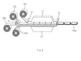
- the radical unit 110 may be manufactured through the following processes (refer to FIG. 3 ). First, a first electrode raw material 121, a first separator raw material 122, a second electrode raw material 123, and a second separator raw material 124 are prepared. After the first and second electrode raw materials 121 and 123 and the first and second separator raw materials 122 and 124 are prepared, the first electrode raw material 121 is cut to a predetermined size using a cutter C1. The second electrode raw material 123 is also cut to a predetermined size using a cutter C2. Then, the first electrode raw material 121 having the predetermined size is placed as a layer on the first separator raw material 122, and the second electrode raw material 123 having the predetermined size is placed as a layer on the second separator raw material 124.
- the first and second electrode raw materials 121 and 123 and the first and second separator raw materials 122 and 124 are supplied to laminators L1 and L2.
- the laminators L1 and L2 press electrode raw materials and separator raw materials, or heat and press the electrode raw materials and the separator raw materials to adhere the electrode raw materials and the separator raw materials to one another.
- Such an adhering process further facilitates the stacking the radical units in the radical unit stacking stage.
- the adhering process facilitates alignment of the electrode assembly.
- the first separator raw material 122 and the second separator raw material 124 are cut to a predetermined size using a cutter C3 to manufacture the radical unit 110.
- a surface of a separator may be coated with a coating material having adhesive force.
- the coating material may be a mixture of inorganic particles and a binder polymer.
- the inorganic particles may improve thermal stability of the separator. That is, the inorganic particles may prevent the separator from contracting at a high temperature.
- the binder polymer may fix the inorganic particles. Accordingly, the inorganic particles may form a porous structure in a coating layer of the separator. The porous structure may provide excellent ion permeability to the separator (although the separator has the coating layer).
- the binder polymer may improve mechanical stability of the separator by fixing the inorganic particles to the separator. Furthermore, the binder polymer may more stably adhere the separator to an electrode (which is called safety-reinforcing separator (SRS) coating).
- SRS safety-reinforcing separator
- the separator may be formed of a polyolefin-based separator base material.
- the first and second electrodes 111 and 113 are disposed on both side surfaces of the first separator 112, and the second electrode 113 is disposed on only one surface of the second separator 114.
- both the surfaces of the first separator 112 may be coated with a coating material, and only the surface of the second separator 114 may be coated with the coating material. That is, both the surfaces of the first separator 112, which face the first and second electrodes 111 and 113, may be coated with the coating material, and only the surface of the second separator 114, which faces the second electrode 113, may be coated with the coating material.
- radical units 110 may be adhered to each other, which will be described later, and thus, both surfaces of the second separator 114 may be coated with the coating material. That is, the surface of the second separator 114 facing the second electrode 113, and the opposite surface of the second separator 114 thereto may be coated with the coating material.
- the radical unit 110 may not have the four-layer structure.
- the radical unit 110 may have an eight-layer structure formed by sequentially stacking the first electrode 111, the first separator 112, the second electrode 113, the second separator 114, the first electrode 111, the first separator 112, the second electrode 113, and the second separator 114. That is, the radical unit 110 may have a structure formed by repeatedly stacking the four-layer structure.
- an electrode assembly 100 is manufactured by stacking at least two radical units 110a.
- each of the radical units 110a is a unit. That is, the electrode assembly 100 is manufactured by repeatedly stacking the radical unit 110a manufactured in the radical unit manufacturing stage. Accordingly, the radical units 110 can be very accurately aligned, and be more efficiently produced.
- the radical unit 110 of the electrode assembly 100 may be detached from each other, the radical unit 110 may be fixed to ensure stacking stability. To this end, after all the radical units 110 are stacked to manufacture the electrode assembly 100, a heating press may press the electrode assembly 100 from the upper and lower sides of the electrode assembly 100.
- the electrode assembly 100 when the electrode assembly 100 is thick, heat transfer to the central part of the electrode assembly 100 may be difficult. In this case, adhesion between the radical units 110 in the central part of the electrode assembly 100 may be difficult. To prevent this issue, the electrode assembly 100 may be pressed at a high temperature. In this case, a separator may be deformed in an outer part of the electrode assembly 100 to which the high temperature is directly applied.
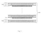
- the radical units are adhered to one another by heating and pressing an outermost one of the radical units. That is, referring to FIGS. 5A, 5B, and 5C , for example, whenever one of the radical units 110 is stacked, a heating press 160 may press the radical unit 110 from the upper side of the radical unit 110. A period in which the heating press 160 presses the radical unit 110 may be appropriately determined according to heat transfer. That is, whenever two or more of the radical units 110 are stacked, the heating press 160 may press the radical units 110, provided that heat can be sufficiently transferred down to the inside of the radical units 110.
- the heating press 160 may include a heater 163 therein for heating.
- the heating press 160 may have a pressing surface 165 having a shape corresponding to the shape of a flat end surface of the radical units 110. In this case, the radical units 110 can be more efficiently pressed, without sacrificing the alignment of the radical units 110.
- Electrodes and separators generally have a rectangular shape.
- the flat end surface of the radical units 110 may be rectangular.
- the heating press 160 presses the whole of the radical unit 110. That is, the heating press 160 is in surface contact with the radical unit 110 while the heating press 160 presses the radical unit 110. Accordingly, the heating press 160 presses the radical unit 110, without sacrificing the alignment of the radical units 110.
- the radical units 110 may be misaligned. This is because the roll should gradually move from an edge of the radical unit 110 to the opposite edge thereof to press the radical unit 110.
- the pressing surface 165 may be greater than electrodes. Electrodes may be smaller than separators for electrical insulation. Thus, when the pressing surface 165 is greater than electrodes, the pressing surface 165 may simultaneously press the whole of adhesion surfaces between the electrodes and separators.
- the heating press 160 may press the radical unit 110 at a pressure ranging from about 50 kgf/cm 2 to about 100 kgf/cm 2 . If the heating press 160 presses the radical unit 110 at a pressure lower than about 50 kgf/cm 2 , adhesion between a separator and an electrode of the radical unit 110 may be difficult. In addition, even when the separator and the electrode are adhered to each other, the separator and the electrode may be easily detached from each other. If the heating press 160 presses the radical unit 110 at a pressure higher than about 100 kgf/cm 2 , a separator of the radical unit 110 may be damaged.
- the heating press 160 may press the radical unit 110 heated to a temperature ranging from about 80°C to about 100°C. If the heating press 160 presses the radical unit 110 at a temperature lower than about 80°C, adhesion between a separator and an electrode of the radical unit 110 may be difficult. In addition, even when the separator and the electrode are adhered to each other, the separator and the electrode may be easily detached from each other. If the heating press 160 presses the radical unit 110 at a temperature higher than about 100°C, pores of a separator of the radical unit 110 may be clogged.
- the heating press 160 may press the radical unit 110 for about 1 second to about 3 seconds. If the heating press 160 presses the radical unit 110 for a time shorter than about 1 second, adhesion between a separator and an electrode of the radical unit 110 may be difficult. In addition, even when the separator and the electrode are adhered to each other, the separator and the electrode may be easily detached from each other. If the heating press 160 presses the radical unit 110 for a time longer than about 3 seconds, a production tact time may be increased.
- the electrode assembly 100 may further include at least one of a first auxiliary unit 130 and a second auxiliary unit 140. That is, in the radical unit stacking stage, at least one of the first auxiliary unit 130 and the second auxiliary unit 140 may be further disposed as a layer in the electrode assembly 100. In this case, an auxiliary unit may be disposed after all radical units are stacked. Alternatively, the radical units may be sequentially stacked on the auxiliary unit.
- the radical unit 110 is formed by sequentially stacking the first electrode 111, the first separator 112, the second electrode 113, and the second separator 114.
- a first electrode 116 (referred to as "a first distal end electrode” hereinafter) is disposed on the uppermost or lowermost side of the electrode assembly 100 formed by stacking the radical units 110.
- the first auxiliary unit 130 is additionally disposed as a layer on the first distal end electrode 116 (which may be a cathode or an anode).
- a first auxiliary unit 130a may be formed by sequentially stacking a separator 114, an anode 113, a separator 112, and a cathode 111 from a first distal end electrode 116, that is, outwardly from the first distal end electrode 116 (to the upper side of FIG. 6 ).
- a first auxiliary unit 130b may be formed by sequentially stacking a separator 114 and a cathode 113 from a first distal end electrode 116, that is, outwardly from the first distal end electrode 116.
- a cathode may be disposed on an outermost side of the electrode assembly 100 adjacent to the first distal end electrode 116, by using the first auxiliary unit 130.
- An electrode may include a collector and an active material layer that is applied to both surfaces of the collector. Accordingly, referring to FIG. 6 , an active material layer of a cathode disposed under a collector reacts with an active material layer of an anode disposed above a collector, through a separator.
- radical units 110 are formed in the same manner and are then sequentially stacked to form an electrode assembly 100, both surfaces of a collector of a first distal end electrode disposed on the uppermost or lowermost side of the electrode assembly 100 are provided with active material layers, like first electrodes. However, in this case, the active material layer of the first distal end electrode disposed at an outside of the electrode assembly 100 does not react with another active material layer, which causes a waste of active material layers.
- the first auxiliary unit 130 is formed separately from the radical units 110.
- the first auxiliary unit 130 may include a cathode having a collector, only a surface of which is coated with an active material layer. That is, a cathode of the first auxiliary unit 130 may include a collector, and only one surface of the collector facing the radical units 110 (only a surface facing the lower side of FIG. 6 ) may be coated with an active material layer.
- a cathode when a first auxiliary unit 130 is disposed on a first distal end electrode 116 to form an electrode assembly 100, a cathode, only one surface of which is coated, may be disposed on an outermost side of the first distal end electrode 116, thus preventing a waste of active material layers.
- a cathode is a configuration for discharging, for example, nickel ions, when the cathode is disposed on the outermost side of an electrode assembly, battery capacity is improved.
- the second auxiliary unit 140 basically performs the same function as that of the first auxiliary unit 130.
- a radical unit 110 is formed by sequentially stacking a first electrode 111, a first separator 112, a second electrode 113, and a second separator 114 from the upper side of the radical unit 110 to the lower side, or from the lower side of the radical unit 110 to the upper side.
- a second separator 117 (referred to as " a second distal end separator” hereinafter) is disposed on the uppermost or lowermost side of the electrode assembly 100 formed by stacking the radical units 110
- the second auxiliary unit 140 is additionally disposed as a layer on the second distal end separator 117.
- a second auxiliary unit 140a may be formed as a cathode 111.
- a second auxiliary unit 140b may be formed by sequentially stacking an anode 111, a separator 112, and a cathode 113 from a second distal end separator 117, that is, outwardly from the second distal end separator 117.
- a cathode of the second auxiliary unit 140 may include a collector, and only one surface of the collector facing the radical units 110 (only a surface facing the upper side of FIG. 9 ) may be coated with an active material layer.
- a cathode when a second auxiliary unit 140 is disposed on a second distal end separator 117 to form an electrode assembly 100, a cathode, only one surface of which is coated, may be disposed on an outermost side of the second distal end separator 117.
- the first auxiliary unit 130 and the second auxiliary unit 140 may further include a separator on an outermost side thereof, if necessary.
- the first auxiliary unit 130 and the second auxiliary unit 140 may further include a separator on an outermost side of the cathode.
- a separator may be further provided on a cathode exposed on a side of an electrode assembly 100 opposite to a second auxiliary unit 140, that is, on the uppermost side of an electrode assembly as illustrated in FIG. 8 .
- an electrode assembly may be formed.
- an electrode assembly 100e may be formed.
- a radical unit 110b may be formed by sequentially stacking a first electrode 111, a first separator 112, a second electrode 113, and a second separator 114 from the lower side of the radical unit 110b to the upper side thereof.
- the first electrode 111 may be a cathode
- the second electrode 113 may be an anode.
- a first auxiliary unit 130c may be formed by sequentially stacking a separator 114, an anode 113, a separator 112, and a cathode 111 from a first distal end electrode 116, that is, from the upper side of FIG. 10 to the lower side thereof.
- An active material layer may be formed on only a surface of the cathode 111 of the first auxiliary unit 130c facing the radical unit 110b.
- a second auxiliary unit 140c may be formed by sequentially stacking a cathode 111 (a first cathode), a separator 112, an anode 113, a separator 114, and a cathode 118 (a second cathode) from a second distal end separator 117.
- the cathode 118 (the second cathode) of the second auxiliary unit 140c which is disposed an outermost side thereof, may include an active material layer on only a surface facing the radical unit 110b.
- an auxiliary unit including a separator facilitates alignment of units.
- an electrode assembly 100f may be formed.
- a radical unit 110b may be formed by sequentially stacking a first electrode 111, a first separator 112, a second electrode 113, and a second separator 114 from the lower side of the radical unit 110b to the upper side thereof.
- the first electrode 111 may be a cathode
- the second electrode 113 may be an anode.
- a first auxiliary unit 130d may be formed by sequentially stacking a separator 114, an anode 113, and a separator 112 from a first distal end electrode 116. In this case, a second auxiliary unit may not be provided.
- an anode may react with an aluminum layer of an electrode case due to a potential difference therebetween. Thus, the anode may be insulated from the electrode case by a separator.
- an electrode assembly 100g may be formed.
- a radical unit 110c may be formed by sequentially stacking a first electrode 111, a first separator 112, a second electrode 113, and a second separator 114 from the upper side of the radical unit 110c to the lower side thereof.
- the first electrode 111 may be an anode
- the second electrode 113 may be a cathode.
- a second auxiliary unit 140d may be formed by sequentially stacking an anode 111, a separator 112, a cathode 113, a separator 114, and an anode 119 from a second distal end separator 117. In this case, a first auxiliary unit may not be provided.
Landscapes
- Chemical & Material Sciences (AREA)
- Chemical Kinetics & Catalysis (AREA)
- Electrochemistry (AREA)
- General Chemical & Material Sciences (AREA)
- Engineering & Computer Science (AREA)
- Manufacturing & Machinery (AREA)
- Inorganic Chemistry (AREA)
- Composite Materials (AREA)
- Materials Engineering (AREA)
- Physics & Mathematics (AREA)
- Thermal Sciences (AREA)
- Secondary Cells (AREA)
- Cell Separators (AREA)
- Battery Electrode And Active Subsutance (AREA)
Applications Claiming Priority (2)
| Application Number | Priority Date | Filing Date | Title |
|---|---|---|---|
| KR1020130113722A KR101561735B1 (ko) | 2013-09-25 | 2013-09-25 | 전극조립체 제조방법 |
| PCT/KR2014/008921 WO2015046893A1 (ko) | 2013-09-25 | 2014-09-25 | 전극조립체 제조방법 |
Publications (3)
| Publication Number | Publication Date |
|---|---|
| EP2892101A1 true EP2892101A1 (de) | 2015-07-08 |
| EP2892101A4 EP2892101A4 (de) | 2015-09-02 |
| EP2892101B1 EP2892101B1 (de) | 2018-05-30 |
Family
ID=52743927
Family Applications (1)
| Application Number | Title | Priority Date | Filing Date |
|---|---|---|---|
| EP14835648.8A Active EP2892101B1 (de) | 2013-09-25 | 2014-09-25 | Verfahren zur herstellung einer elektrodenanordnung |
Country Status (7)
| Country | Link |
|---|---|
| US (1) | US10135090B2 (de) |
| EP (1) | EP2892101B1 (de) |
| JP (1) | JP5987118B2 (de) |
| KR (1) | KR101561735B1 (de) |
| CN (1) | CN104718655B (de) |
| TW (1) | TWI566942B (de) |
| WO (1) | WO2015046893A1 (de) |
Cited By (1)
| Publication number | Priority date | Publication date | Assignee | Title |
|---|---|---|---|---|
| CN107069056A (zh) * | 2016-12-30 | 2017-08-18 | 深圳市赢合科技股份有限公司 | 一种电池折边装置和方法 |
Families Citing this family (23)
| Publication number | Priority date | Publication date | Assignee | Title |
|---|---|---|---|---|
| JP6521825B2 (ja) * | 2015-10-14 | 2019-05-29 | トヨタ自動車株式会社 | 積層型電池の製造方法 |
| CN105633451B (zh) * | 2015-12-29 | 2018-06-05 | 深圳市优特利电源有限公司 | 超薄型聚合物电池及制作方法 |
| KR102089537B1 (ko) * | 2016-04-15 | 2020-03-16 | 주식회사 엘지화학 | 이차전지용 적층시스템 |
| CN105870511B (zh) * | 2016-06-13 | 2019-06-21 | 合肥国轩高科动力能源有限公司 | 一种锂离子叠片电池电芯的制造方法 |
| CN106159347A (zh) * | 2016-07-05 | 2016-11-23 | 深圳吉阳智云科技有限公司 | 复合式叠片电芯及其叠片单元和叠片方法 |
| JP6961329B2 (ja) * | 2016-07-07 | 2021-11-05 | 三洋電機株式会社 | 電池の製造方法 |
| CN106785071A (zh) * | 2017-02-24 | 2017-05-31 | 合肥国轩高科动力能源有限公司 | 一种电池单元的热复合工艺 |
| JP6787241B2 (ja) * | 2017-04-28 | 2020-11-18 | トヨタ自動車株式会社 | 電極積層体及び電池の製造方法 |
| CN107204488A (zh) * | 2017-05-12 | 2017-09-26 | 深圳市格林晟科技有限公司 | 一种复合叠片方法 |
| ES2942264T3 (es) * | 2017-08-11 | 2023-05-31 | Lg Energy Solution Ltd | Conjunto de electrodos, método de fabricación del mismo y batería secundaria que incluye el mismo |
| JP7069625B2 (ja) * | 2017-10-06 | 2022-05-18 | 株式会社Gsユアサ | 蓄電素子の製造方法 |
| CN109560252B (zh) * | 2017-12-29 | 2022-05-24 | 蜂巢能源科技有限公司 | 电极层叠组件的制造方法以及电极层叠组件 |
| JP6907995B2 (ja) * | 2018-04-26 | 2021-07-21 | トヨタ自動車株式会社 | 積層電極体 |
| US10819706B2 (en) * | 2018-07-09 | 2020-10-27 | Igt | System, apparatus and method for facilitating remote gaming communications in a venue |
| KR102328527B1 (ko) * | 2018-12-24 | 2021-11-18 | 주식회사 엘지에너지솔루션 | 벤딩 현상이 개선된 스택형 전극 조립체 및 이의 제조방법 |
| KR102580441B1 (ko) * | 2019-03-06 | 2023-09-20 | 주식회사 엘지에너지솔루션 | 셀 제조 장치 및 방법 |
| KR102733271B1 (ko) * | 2019-06-21 | 2024-11-25 | 삼성에스디아이 주식회사 | 전극 조립체의 제조 방법 |
| CN111769335A (zh) * | 2020-08-11 | 2020-10-13 | 湖北亿纬动力有限公司 | 一种热压工艺及热压装置 |
| EP4156360B1 (de) * | 2021-03-31 | 2026-04-29 | LG Energy Solution, Ltd. | Vorrichtung zur herstellung von einzelzellen mit glanzmesser und herstellungsverfahren damit |
| US12244037B2 (en) | 2021-07-09 | 2025-03-04 | Lg Energy Solution, Ltd. | Manufacturing method for electrode assembly |
| KR102569078B1 (ko) * | 2021-07-09 | 2023-08-23 | 주식회사 엘지에너지솔루션 | 전극 조립체 제조 방법 |
| WO2023282722A1 (en) * | 2021-07-09 | 2023-01-12 | Lg Energy Solution, Ltd. | Assembly manufacturing equipment and method for electrode assembly |
| KR102742757B1 (ko) * | 2022-12-07 | 2024-12-12 | 주식회사 엘지에너지솔루션 | 전극 조립체 및 이의 제조 방법 |
Family Cites Families (21)
| Publication number | Priority date | Publication date | Assignee | Title |
|---|---|---|---|---|
| US6190426B1 (en) | 1998-12-17 | 2001-02-20 | Moltech Corporation | Methods of preparing prismatic cells |
| KR100497147B1 (ko) | 2000-02-08 | 2005-06-29 | 주식회사 엘지화학 | 다중 중첩 전기화학 셀 및 그의 제조방법 |
| KR100515571B1 (ko) * | 2000-02-08 | 2005-09-20 | 주식회사 엘지화학 | 중첩 전기 화학 셀 |
| TW499766B (en) | 2000-03-29 | 2002-08-21 | Elite Ionergy Co Ltd | Battery manufacturing method |
| WO2005091410A1 (ja) * | 2004-03-19 | 2005-09-29 | Nec Corporation | 固体電解質型燃料電池 |
| US20060115718A1 (en) * | 2004-11-30 | 2006-06-01 | Delphi Technologies, Inc. | Lithium ion polymer multi-cell and method of making |
| JP4929592B2 (ja) | 2004-12-27 | 2012-05-09 | パナソニック株式会社 | エネルギーデバイスの製造法 |
| US8734986B2 (en) | 2007-07-11 | 2014-05-27 | Nissan Motor Co., Ltd. | Laminate type battery |
| JP5353032B2 (ja) * | 2007-07-11 | 2013-11-27 | 日産自動車株式会社 | 積層型電池 |
| KR101150258B1 (ko) | 2007-07-16 | 2012-06-12 | 주식회사 엘지화학 | 열적 안정성이 우수한 전극조립체 및 이를 포함하는이차전지 |
| KR101040482B1 (ko) * | 2008-03-04 | 2011-06-09 | 주식회사 엘지화학 | 다공성 코팅층이 코팅된 세퍼레이터 및 이를 구비한 전기화학소자 |
| JP2012526857A (ja) | 2009-05-16 | 2012-11-01 | トルテック コーポレーション | 静電的に帯電した多作用性経鼻適用、製品及び方法 |
| KR101050288B1 (ko) | 2009-10-01 | 2011-07-19 | 삼성에스디아이 주식회사 | 전극 조립체 및 이를 갖는 이차 전지 |
| CN102884665B (zh) * | 2010-04-06 | 2015-09-30 | 株式会社Lg化学 | 改进的堆叠型电池胞或者双电池胞、用于使用该电池胞的二次电池的电极组件及其制造方法 |
| KR101473048B1 (ko) | 2011-08-08 | 2014-12-16 | (주) 엘지토스템비엠 | 결로수 배출 유닛을 구비하는 시스템 창호와 결로수 배출 유닛 |
| TWI484681B (zh) | 2012-05-23 | 2015-05-11 | Lg化學股份有限公司 | 電極組之製造方法及包含電極組之電化學電池 |
| JP5969131B2 (ja) * | 2013-02-15 | 2016-08-17 | エルジー・ケム・リミテッド | 電極組立体の製造方法 |
| EP2958179B1 (de) | 2013-02-15 | 2017-06-21 | LG Chem, Ltd. | Elektrodenanordnung mit verbesserter sicherheit und herstellungsverfahren dafür |
| TWI520407B (zh) | 2013-02-15 | 2016-02-01 | Lg化學股份有限公司 | 電極組 |
| KR101567675B1 (ko) | 2013-02-15 | 2015-11-10 | 주식회사 엘지화학 | 전극조립체 및 이를 포함하는 폴리머 이차전지 셀 |
| KR101595643B1 (ko) | 2013-02-15 | 2016-02-18 | 주식회사 엘지화학 | 전극조립체 및 이를 포함하는 폴리머 이차전지 셀 |
-
2013
- 2013-09-25 KR KR1020130113722A patent/KR101561735B1/ko active Active
-
2014
- 2014-09-25 CN CN201480002319.6A patent/CN104718655B/zh active Active
- 2014-09-25 JP JP2015539534A patent/JP5987118B2/ja active Active
- 2014-09-25 TW TW103133299A patent/TWI566942B/zh active
- 2014-09-25 US US14/423,792 patent/US10135090B2/en active Active
- 2014-09-25 EP EP14835648.8A patent/EP2892101B1/de active Active
- 2014-09-25 WO PCT/KR2014/008921 patent/WO2015046893A1/ko not_active Ceased
Cited By (2)
| Publication number | Priority date | Publication date | Assignee | Title |
|---|---|---|---|---|
| CN107069056A (zh) * | 2016-12-30 | 2017-08-18 | 深圳市赢合科技股份有限公司 | 一种电池折边装置和方法 |
| CN107069056B (zh) * | 2016-12-30 | 2019-05-21 | 深圳市赢合科技股份有限公司 | 一种电池折边装置和方法 |
Also Published As
| Publication number | Publication date |
|---|---|
| EP2892101A4 (de) | 2015-09-02 |
| TW201527113A (zh) | 2015-07-16 |
| KR20150033887A (ko) | 2015-04-02 |
| US10135090B2 (en) | 2018-11-20 |
| US20160036087A1 (en) | 2016-02-04 |
| CN104718655A (zh) | 2015-06-17 |
| JP2015531989A (ja) | 2015-11-05 |
| EP2892101B1 (de) | 2018-05-30 |
| KR101561735B1 (ko) | 2015-10-19 |
| JP5987118B2 (ja) | 2016-09-07 |
| CN104718655B (zh) | 2017-12-19 |
| TWI566942B (zh) | 2017-01-21 |
| WO2015046893A1 (ko) | 2015-04-02 |
Similar Documents
| Publication | Publication Date | Title |
|---|---|---|
| EP2892101B1 (de) | Verfahren zur herstellung einer elektrodenanordnung | |
| KR102138988B1 (ko) | 나노다공성 세퍼레이터층을 이용한 리튬 배터리 | |
| EP3331083B1 (de) | Verfahren zur herstellung einer sekundärbatterie und verfahren zur herstellung einer elektrodenanordnung | |
| EP2892102B1 (de) | Verfahren zur herstellung einer elektrodenanordnung | |
| EP2866290B1 (de) | Elektrodenanordnung für polymersekundärbatteriezelle | |
| KR102241199B1 (ko) | 절첩된 전극 및 분리막을 갖는 전기화학 전지, 이를 포함하는 배터리, 및 이들의 제조 방법 | |
| KR101595621B1 (ko) | 전극조립체 제조방법 | |
| US20200028200A1 (en) | Method for producing an electrode unit for a battery cell and electrode unit | |
| JP7160922B2 (ja) | 固体電池用正極、固体電池用正極の製造方法、および固体電池 | |
| KR101784033B1 (ko) | 전극조립체 제조방법 | |
| KR20170055421A (ko) | 이차전지 및 그의 제조방법 | |
| CN217426818U (zh) | 全固态电芯和全固态电池 | |
| US11424474B2 (en) | Secondary battery, and apparatus and method for manufacturing the same | |
| JP7572114B2 (ja) | 単位セルおよびこれを含む電池セル | |
| JP7600509B2 (ja) | 絶縁性コート層が形成された分離膜を含む二次電池用ユニットセル、およびその製造方法 | |
| KR102217444B1 (ko) | 전극조립체 및 그 전극조립체의 제조 방법 | |
| WO2012002359A1 (ja) | 蓄電デバイスとその製造方法 | |
| KR20230085094A (ko) | 전극조립체, 이의 제조방법, 및 이를 포함하는 리튬 이차전지 | |
| KR101750237B1 (ko) | 비대칭 구조의 단위셀 제조방법 및 그 제조방법에 의해 제조된 단위셀 | |
| KR20040009583A (ko) | 리튬 이온 폴리머 전지용 극판 조립체,이를 이용한 리튬이온 폴리머 전지 및 리튬 이온 폴리머 전지의 제조방법 |
Legal Events
| Date | Code | Title | Description |
|---|---|---|---|
| PUAI | Public reference made under article 153(3) epc to a published international application that has entered the european phase |
Free format text: ORIGINAL CODE: 0009012 |
|
| 17P | Request for examination filed |
Effective date: 20150218 |
|
| AK | Designated contracting states |
Kind code of ref document: A1 Designated state(s): AL AT BE BG CH CY CZ DE DK EE ES FI FR GB GR HR HU IE IS IT LI LT LU LV MC MK MT NL NO PL PT RO RS SE SI SK SM TR |
|
| AX | Request for extension of the european patent |
Extension state: BA ME |
|
| RIC1 | Information provided on ipc code assigned before grant |
Ipc: H01M 10/04 20060101AFI20150722BHEP Ipc: H01M 10/058 20100101ALI20150722BHEP |
|
| RA4 | Supplementary search report drawn up and despatched (corrected) |
Effective date: 20150730 |
|
| DAX | Request for extension of the european patent (deleted) | ||
| STAA | Information on the status of an ep patent application or granted ep patent |
Free format text: STATUS: EXAMINATION IS IN PROGRESS |
|
| 17Q | First examination report despatched |
Effective date: 20170606 |
|
| GRAP | Despatch of communication of intention to grant a patent |
Free format text: ORIGINAL CODE: EPIDOSNIGR1 |
|
| RIC1 | Information provided on ipc code assigned before grant |
Ipc: H01M 10/058 20100101ALI20171214BHEP Ipc: B32B 37/12 20060101ALI20171214BHEP Ipc: H01M 10/04 20060101AFI20171214BHEP |
|
| STAA | Information on the status of an ep patent application or granted ep patent |
Free format text: STATUS: GRANT OF PATENT IS INTENDED |
|
| INTG | Intention to grant announced |
Effective date: 20180118 |
|
| GRAS | Grant fee paid |
Free format text: ORIGINAL CODE: EPIDOSNIGR3 |
|
| GRAA | (expected) grant |
Free format text: ORIGINAL CODE: 0009210 |
|
| STAA | Information on the status of an ep patent application or granted ep patent |
Free format text: STATUS: THE PATENT HAS BEEN GRANTED |
|
| AK | Designated contracting states |
Kind code of ref document: B1 Designated state(s): AL AT BE BG CH CY CZ DE DK EE ES FI FR GB GR HR HU IE IS IT LI LT LU LV MC MK MT NL NO PL PT RO RS SE SI SK SM TR |
|
| REG | Reference to a national code |
Ref country code: GB Ref legal event code: FG4D |
|
| REG | Reference to a national code |
Ref country code: CH Ref legal event code: EP |
|
| REG | Reference to a national code |
Ref country code: AT Ref legal event code: REF Ref document number: 1004537 Country of ref document: AT Kind code of ref document: T Effective date: 20180615 |
|
| REG | Reference to a national code |
Ref country code: IE Ref legal event code: FG4D |
|
| REG | Reference to a national code |
Ref country code: DE Ref legal event code: R096 Ref document number: 602014026469 Country of ref document: DE |
|
| REG | Reference to a national code |
Ref country code: FR Ref legal event code: PLFP Year of fee payment: 5 |
|
| REG | Reference to a national code |
Ref country code: NL Ref legal event code: MP Effective date: 20180530 |
|
| REG | Reference to a national code |
Ref country code: LT Ref legal event code: MG4D |
|
| PG25 | Lapsed in a contracting state [announced via postgrant information from national office to epo] |
Ref country code: NO Free format text: LAPSE BECAUSE OF FAILURE TO SUBMIT A TRANSLATION OF THE DESCRIPTION OR TO PAY THE FEE WITHIN THE PRESCRIBED TIME-LIMIT Effective date: 20180830 Ref country code: BG Free format text: LAPSE BECAUSE OF FAILURE TO SUBMIT A TRANSLATION OF THE DESCRIPTION OR TO PAY THE FEE WITHIN THE PRESCRIBED TIME-LIMIT Effective date: 20180830 Ref country code: CY Free format text: LAPSE BECAUSE OF FAILURE TO SUBMIT A TRANSLATION OF THE DESCRIPTION OR TO PAY THE FEE WITHIN THE PRESCRIBED TIME-LIMIT Effective date: 20180530 Ref country code: SE Free format text: LAPSE BECAUSE OF FAILURE TO SUBMIT A TRANSLATION OF THE DESCRIPTION OR TO PAY THE FEE WITHIN THE PRESCRIBED TIME-LIMIT Effective date: 20180530 Ref country code: FI Free format text: LAPSE BECAUSE OF FAILURE TO SUBMIT A TRANSLATION OF THE DESCRIPTION OR TO PAY THE FEE WITHIN THE PRESCRIBED TIME-LIMIT Effective date: 20180530 Ref country code: LT Free format text: LAPSE BECAUSE OF FAILURE TO SUBMIT A TRANSLATION OF THE DESCRIPTION OR TO PAY THE FEE WITHIN THE PRESCRIBED TIME-LIMIT Effective date: 20180530 Ref country code: ES Free format text: LAPSE BECAUSE OF FAILURE TO SUBMIT A TRANSLATION OF THE DESCRIPTION OR TO PAY THE FEE WITHIN THE PRESCRIBED TIME-LIMIT Effective date: 20180530 |
|
| PG25 | Lapsed in a contracting state [announced via postgrant information from national office to epo] |
Ref country code: LV Free format text: LAPSE BECAUSE OF FAILURE TO SUBMIT A TRANSLATION OF THE DESCRIPTION OR TO PAY THE FEE WITHIN THE PRESCRIBED TIME-LIMIT Effective date: 20180530 Ref country code: HR Free format text: LAPSE BECAUSE OF FAILURE TO SUBMIT A TRANSLATION OF THE DESCRIPTION OR TO PAY THE FEE WITHIN THE PRESCRIBED TIME-LIMIT Effective date: 20180530 Ref country code: GR Free format text: LAPSE BECAUSE OF FAILURE TO SUBMIT A TRANSLATION OF THE DESCRIPTION OR TO PAY THE FEE WITHIN THE PRESCRIBED TIME-LIMIT Effective date: 20180831 Ref country code: RS Free format text: LAPSE BECAUSE OF FAILURE TO SUBMIT A TRANSLATION OF THE DESCRIPTION OR TO PAY THE FEE WITHIN THE PRESCRIBED TIME-LIMIT Effective date: 20180530 |
|
| REG | Reference to a national code |
Ref country code: AT Ref legal event code: MK05 Ref document number: 1004537 Country of ref document: AT Kind code of ref document: T Effective date: 20180530 |
|
| PG25 | Lapsed in a contracting state [announced via postgrant information from national office to epo] |
Ref country code: NL Free format text: LAPSE BECAUSE OF FAILURE TO SUBMIT A TRANSLATION OF THE DESCRIPTION OR TO PAY THE FEE WITHIN THE PRESCRIBED TIME-LIMIT Effective date: 20180530 |
|
| PG25 | Lapsed in a contracting state [announced via postgrant information from national office to epo] |
Ref country code: DK Free format text: LAPSE BECAUSE OF FAILURE TO SUBMIT A TRANSLATION OF THE DESCRIPTION OR TO PAY THE FEE WITHIN THE PRESCRIBED TIME-LIMIT Effective date: 20180530 Ref country code: AT Free format text: LAPSE BECAUSE OF FAILURE TO SUBMIT A TRANSLATION OF THE DESCRIPTION OR TO PAY THE FEE WITHIN THE PRESCRIBED TIME-LIMIT Effective date: 20180530 Ref country code: PL Free format text: LAPSE BECAUSE OF FAILURE TO SUBMIT A TRANSLATION OF THE DESCRIPTION OR TO PAY THE FEE WITHIN THE PRESCRIBED TIME-LIMIT Effective date: 20180530 Ref country code: EE Free format text: LAPSE BECAUSE OF FAILURE TO SUBMIT A TRANSLATION OF THE DESCRIPTION OR TO PAY THE FEE WITHIN THE PRESCRIBED TIME-LIMIT Effective date: 20180530 Ref country code: CZ Free format text: LAPSE BECAUSE OF FAILURE TO SUBMIT A TRANSLATION OF THE DESCRIPTION OR TO PAY THE FEE WITHIN THE PRESCRIBED TIME-LIMIT Effective date: 20180530 Ref country code: RO Free format text: LAPSE BECAUSE OF FAILURE TO SUBMIT A TRANSLATION OF THE DESCRIPTION OR TO PAY THE FEE WITHIN THE PRESCRIBED TIME-LIMIT Effective date: 20180530 Ref country code: SK Free format text: LAPSE BECAUSE OF FAILURE TO SUBMIT A TRANSLATION OF THE DESCRIPTION OR TO PAY THE FEE WITHIN THE PRESCRIBED TIME-LIMIT Effective date: 20180530 |
|
| PG25 | Lapsed in a contracting state [announced via postgrant information from national office to epo] |
Ref country code: SM Free format text: LAPSE BECAUSE OF FAILURE TO SUBMIT A TRANSLATION OF THE DESCRIPTION OR TO PAY THE FEE WITHIN THE PRESCRIBED TIME-LIMIT Effective date: 20180530 Ref country code: IT Free format text: LAPSE BECAUSE OF FAILURE TO SUBMIT A TRANSLATION OF THE DESCRIPTION OR TO PAY THE FEE WITHIN THE PRESCRIBED TIME-LIMIT Effective date: 20180530 |
|
| REG | Reference to a national code |
Ref country code: DE Ref legal event code: R097 Ref document number: 602014026469 Country of ref document: DE |
|
| PLBE | No opposition filed within time limit |
Free format text: ORIGINAL CODE: 0009261 |
|
| STAA | Information on the status of an ep patent application or granted ep patent |
Free format text: STATUS: NO OPPOSITION FILED WITHIN TIME LIMIT |
|
| PG25 | Lapsed in a contracting state [announced via postgrant information from national office to epo] |
Ref country code: MC Free format text: LAPSE BECAUSE OF FAILURE TO SUBMIT A TRANSLATION OF THE DESCRIPTION OR TO PAY THE FEE WITHIN THE PRESCRIBED TIME-LIMIT Effective date: 20180530 |
|
| REG | Reference to a national code |
Ref country code: CH Ref legal event code: PL |
|
| 26N | No opposition filed |
Effective date: 20190301 |
|
| PG25 | Lapsed in a contracting state [announced via postgrant information from national office to epo] |
Ref country code: SI Free format text: LAPSE BECAUSE OF FAILURE TO SUBMIT A TRANSLATION OF THE DESCRIPTION OR TO PAY THE FEE WITHIN THE PRESCRIBED TIME-LIMIT Effective date: 20180530 |
|
| REG | Reference to a national code |
Ref country code: BE Ref legal event code: MM Effective date: 20180930 |
|
| REG | Reference to a national code |
Ref country code: IE Ref legal event code: MM4A |
|
| PG25 | Lapsed in a contracting state [announced via postgrant information from national office to epo] |
Ref country code: LU Free format text: LAPSE BECAUSE OF NON-PAYMENT OF DUE FEES Effective date: 20180925 |
|
| PG25 | Lapsed in a contracting state [announced via postgrant information from national office to epo] |
Ref country code: IE Free format text: LAPSE BECAUSE OF NON-PAYMENT OF DUE FEES Effective date: 20180925 |
|
| PG25 | Lapsed in a contracting state [announced via postgrant information from national office to epo] |
Ref country code: BE Free format text: LAPSE BECAUSE OF NON-PAYMENT OF DUE FEES Effective date: 20180930 Ref country code: CH Free format text: LAPSE BECAUSE OF NON-PAYMENT OF DUE FEES Effective date: 20180930 Ref country code: LI Free format text: LAPSE BECAUSE OF NON-PAYMENT OF DUE FEES Effective date: 20180930 |
|
| PG25 | Lapsed in a contracting state [announced via postgrant information from national office to epo] |
Ref country code: AL Free format text: LAPSE BECAUSE OF FAILURE TO SUBMIT A TRANSLATION OF THE DESCRIPTION OR TO PAY THE FEE WITHIN THE PRESCRIBED TIME-LIMIT Effective date: 20180530 |
|
| PG25 | Lapsed in a contracting state [announced via postgrant information from national office to epo] |
Ref country code: MT Free format text: LAPSE BECAUSE OF NON-PAYMENT OF DUE FEES Effective date: 20180925 |
|
| PG25 | Lapsed in a contracting state [announced via postgrant information from national office to epo] |
Ref country code: TR Free format text: LAPSE BECAUSE OF FAILURE TO SUBMIT A TRANSLATION OF THE DESCRIPTION OR TO PAY THE FEE WITHIN THE PRESCRIBED TIME-LIMIT Effective date: 20180530 |
|
| PG25 | Lapsed in a contracting state [announced via postgrant information from national office to epo] |
Ref country code: PT Free format text: LAPSE BECAUSE OF FAILURE TO SUBMIT A TRANSLATION OF THE DESCRIPTION OR TO PAY THE FEE WITHIN THE PRESCRIBED TIME-LIMIT Effective date: 20180530 |
|
| PG25 | Lapsed in a contracting state [announced via postgrant information from national office to epo] |
Ref country code: HU Free format text: LAPSE BECAUSE OF FAILURE TO SUBMIT A TRANSLATION OF THE DESCRIPTION OR TO PAY THE FEE WITHIN THE PRESCRIBED TIME-LIMIT; INVALID AB INITIO Effective date: 20140925 Ref country code: MK Free format text: LAPSE BECAUSE OF NON-PAYMENT OF DUE FEES Effective date: 20180530 |
|
| PG25 | Lapsed in a contracting state [announced via postgrant information from national office to epo] |
Ref country code: IS Free format text: LAPSE BECAUSE OF FAILURE TO SUBMIT A TRANSLATION OF THE DESCRIPTION OR TO PAY THE FEE WITHIN THE PRESCRIBED TIME-LIMIT Effective date: 20180930 |
|
| P01 | Opt-out of the competence of the unified patent court (upc) registered |
Effective date: 20230512 |
|
| REG | Reference to a national code |
Ref country code: DE Ref legal event code: R081 Ref document number: 602014026469 Country of ref document: DE Owner name: LG ENERGY SOLUTION, LTD., KR Free format text: FORMER OWNER: LG CHEM, LTD., SEOUL, KR |
|
| REG | Reference to a national code |
Ref country code: GB Ref legal event code: 732E Free format text: REGISTERED BETWEEN 20230824 AND 20230831 |
|
| PGFP | Annual fee paid to national office [announced via postgrant information from national office to epo] |
Ref country code: DE Payment date: 20250820 Year of fee payment: 12 |
|
| PGFP | Annual fee paid to national office [announced via postgrant information from national office to epo] |
Ref country code: GB Payment date: 20250820 Year of fee payment: 12 |
|
| PGFP | Annual fee paid to national office [announced via postgrant information from national office to epo] |
Ref country code: FR Payment date: 20250821 Year of fee payment: 12 |