EP2892149B1 - Dispositif d'activation de thyristor - Google Patents
Dispositif d'activation de thyristor Download PDFInfo
- Publication number
- EP2892149B1 EP2892149B1 EP12883614.5A EP12883614A EP2892149B1 EP 2892149 B1 EP2892149 B1 EP 2892149B1 EP 12883614 A EP12883614 A EP 12883614A EP 2892149 B1 EP2892149 B1 EP 2892149B1
- Authority
- EP
- European Patent Office
- Prior art keywords
- synchronous machine
- rotation speed
- control angle
- voltage
- phase
- Prior art date
- Legal status (The legal status is an assumption and is not a legal conclusion. Google has not performed a legal analysis and makes no representation as to the accuracy of the status listed.)
- Active
Links
Images


Classifications
-
- H—ELECTRICITY
- H02—GENERATION; CONVERSION OR DISTRIBUTION OF ELECTRIC POWER
- H02P—CONTROL OR REGULATION OF ELECTRIC MOTORS, ELECTRIC GENERATORS OR DYNAMO-ELECTRIC CONVERTERS; CONTROLLING TRANSFORMERS, REACTORS OR CHOKE COILS
- H02P1/00—Arrangements for starting electric motors or dynamo-electric converters
- H02P1/16—Arrangements for starting electric motors or dynamo-electric converters for starting dynamo-electric motors or dynamo-electric converters
- H02P1/46—Arrangements for starting electric motors or dynamo-electric converters for starting dynamo-electric motors or dynamo-electric converters for starting an individual synchronous motor
- H02P1/52—Arrangements for starting electric motors or dynamo-electric converters for starting dynamo-electric motors or dynamo-electric converters for starting an individual synchronous motor by progressive increase of frequency of supply to motor
-
- H—ELECTRICITY
- H02—GENERATION; CONVERSION OR DISTRIBUTION OF ELECTRIC POWER
- H02P—CONTROL OR REGULATION OF ELECTRIC MOTORS, ELECTRIC GENERATORS OR DYNAMO-ELECTRIC CONVERTERS; CONTROLLING TRANSFORMERS, REACTORS OR CHOKE COILS
- H02P27/00—Arrangements or methods for the control of AC motors characterised by the kind of supply voltage
- H02P27/04—Arrangements or methods for the control of AC motors characterised by the kind of supply voltage using variable-frequency supply voltage, e.g. inverter or converter supply voltage
- H02P27/047—V/F converter, wherein the voltage is controlled proportionally with the frequency
-
- H—ELECTRICITY
- H02—GENERATION; CONVERSION OR DISTRIBUTION OF ELECTRIC POWER
- H02P—CONTROL OR REGULATION OF ELECTRIC MOTORS, ELECTRIC GENERATORS OR DYNAMO-ELECTRIC CONVERTERS; CONTROLLING TRANSFORMERS, REACTORS OR CHOKE COILS
- H02P1/00—Arrangements for starting electric motors or dynamo-electric converters
- H02P1/16—Arrangements for starting electric motors or dynamo-electric converters for starting dynamo-electric motors or dynamo-electric converters
- H02P1/46—Arrangements for starting electric motors or dynamo-electric converters for starting dynamo-electric motors or dynamo-electric converters for starting an individual synchronous motor
-
- H—ELECTRICITY
- H02—GENERATION; CONVERSION OR DISTRIBUTION OF ELECTRIC POWER
- H02P—CONTROL OR REGULATION OF ELECTRIC MOTORS, ELECTRIC GENERATORS OR DYNAMO-ELECTRIC CONVERTERS; CONTROLLING TRANSFORMERS, REACTORS OR CHOKE COILS
- H02P23/00—Arrangements or methods for the control of AC motors characterised by a control method other than vector control
- H02P23/0086—Arrangements or methods for the control of AC motors characterised by a control method other than vector control specially adapted for high speeds, e.g. above nominal speed
- H02P23/009—Arrangements or methods for the control of AC motors characterised by a control method other than vector control specially adapted for high speeds, e.g. above nominal speed using field weakening
-
- H—ELECTRICITY
- H02—GENERATION; CONVERSION OR DISTRIBUTION OF ELECTRIC POWER
- H02P—CONTROL OR REGULATION OF ELECTRIC MOTORS, ELECTRIC GENERATORS OR DYNAMO-ELECTRIC CONVERTERS; CONTROLLING TRANSFORMERS, REACTORS OR CHOKE COILS
- H02P27/00—Arrangements or methods for the control of AC motors characterised by the kind of supply voltage
- H02P27/04—Arrangements or methods for the control of AC motors characterised by the kind of supply voltage using variable-frequency supply voltage, e.g. inverter or converter supply voltage
- H02P27/16—Arrangements or methods for the control of AC motors characterised by the kind of supply voltage using variable-frequency supply voltage, e.g. inverter or converter supply voltage using AC to AC converters without intermediate conversion to DC
-
- H—ELECTRICITY
- H02—GENERATION; CONVERSION OR DISTRIBUTION OF ELECTRIC POWER
- H02P—CONTROL OR REGULATION OF ELECTRIC MOTORS, ELECTRIC GENERATORS OR DYNAMO-ELECTRIC CONVERTERS; CONTROLLING TRANSFORMERS, REACTORS OR CHOKE COILS
- H02P2201/00—Indexing scheme relating to controlling arrangements characterised by the converter used
- H02P2201/13—DC-link of current link type, e.g. typically for thyristor bridges, having an inductor in series with rectifier
-
- H—ELECTRICITY
- H02—GENERATION; CONVERSION OR DISTRIBUTION OF ELECTRIC POWER
- H02P—CONTROL OR REGULATION OF ELECTRIC MOTORS, ELECTRIC GENERATORS OR DYNAMO-ELECTRIC CONVERTERS; CONTROLLING TRANSFORMERS, REACTORS OR CHOKE COILS
- H02P2209/00—Indexing scheme relating to controlling arrangements characterised by the waveform of the supplied voltage or current
- H02P2209/11—Sinusoidal waveform
-
- H—ELECTRICITY
- H02—GENERATION; CONVERSION OR DISTRIBUTION OF ELECTRIC POWER
- H02P—CONTROL OR REGULATION OF ELECTRIC MOTORS, ELECTRIC GENERATORS OR DYNAMO-ELECTRIC CONVERTERS; CONTROLLING TRANSFORMERS, REACTORS OR CHOKE COILS
- H02P27/00—Arrangements or methods for the control of AC motors characterised by the kind of supply voltage
- H02P27/04—Arrangements or methods for the control of AC motors characterised by the kind of supply voltage using variable-frequency supply voltage, e.g. inverter or converter supply voltage
- H02P27/06—Arrangements or methods for the control of AC motors characterised by the kind of supply voltage using variable-frequency supply voltage, e.g. inverter or converter supply voltage using DC to AC converters or inverters
Definitions
- This invention relates to a thyristor starter, and particularly to a thyristor starter starting a synchronous machine.
- a thyristor starter includes a converter converting three-phase AC power to DC power, a DC reactor smoothing DC power, and an inverter converting DC power provided from the converter through the DC reactor to three-phase AC power at a desired frequency and providing the three-phase AC power to a synchronous machine.
- a method of controlling an inverter includes a first method of setting a phase control angle to a constant value and a second method of increasing a phase control angle from a minimum value to a maximum value at a constant rate of increase in accordance with a rotation speed of a synchronous machine (see, for example, Japanese Patent Laying-Open No. 2003-61380 (PTD 1)).
- PTD 2 discloses a control device for a thyristor motor by which the advance angle is switched at a predetermined slow rate of change in order to avoid an abrupt change in the motor torque.
- a primary object of this invention is to provide a thyristor starter capable of achieving reduction in size and improvement in efficiency in use of a converter.
- a thyristor starter according to this invention as defined in claim 1 is a thyristor starter for starting a synchronous machine, including a converter converting first AC power to DC power, an inverter converting the DC power to second AC power at a variable frequency and supplying the second AC power to the synchronous machine, a speed operation portion finding a rotation speed of the synchronous machine, a control angle operation portion including a function or a table showing relation between the rotation speed of the synchronous machine and a phase control angle of the inverter and finding a phase control angle having a value in accordance with the rotation speed of the synchronous machine found by the speed operation portion, and a control unit controlling the inverter based on the phase control angle found by the control angle operation portion.
- control angle operation portion varies the phase control angle from a minimum value to a maximum value in accordance with the rotation speed of the synchronous machine, and the control angle operation portion varies a rate of increase in phase control angle relative to the rotation speed of the synchronous machine in a plurality of steps in accordance with the rotation speed of the synchronous machine such that a DC voltage which appears at an input terminal of the inverter is constant in spite of variation in rotation speed of the synchronous machine.
- the rate of increase in phase control angle relative to the rotation speed of the synchronous machine decreases in a plurality of steps in accordance with the rotation speed of the synchronous machine.
- a voltage detector detecting a three-phase AC voltage output from the synchronous machine is included, and the speed operation portion finds a rotation speed of the synchronous machine based on the three-phase AC voltage detected by the voltage detector.
- a position detector detecting a position of a rotor of the synchronous machine is included, and the speed operation portion finds a rotation speed of the synchronous machine based on a result of detection by the position detector.
- the synchronous machine is a generator of a thermal power station.
- a phase control angle of the inverter varies from a minimum value to a maximum value in accordance with a rotation speed of the synchronous machine, and a rate of increase in phase control angle relative to the rotation speed of the synchronous machine is varied in a plurality of steps in accordance with the rotation speed of the synchronous machine. Therefore, variation in DC voltage which appears on the side of the input terminal of the inverter can be suppressed to be less, and reduction in size and improvement in efficiency in use of the converter can be achieved.
- a generator implemented by a synchronous machine is coupled to a gas turbine, and the generator is rotationally driven by the gas turbine.
- a thyristor starter is an apparatus starting the generator and the gas turbine which have been stopped, by rotating the generator which has been stopped to a prescribed rotation speed from which the gas turbine can speed up in a self-sustained manner.
- the thyristor starter is generally called a load commutated inverter (LCI).
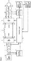
- a thyristor starter includes a transformer 1, a converter 2, a DC reactor 3, and an inverter 4, as shown in Fig. 1 .
- Transformer 1 converts a three-phase AC voltage supplied from an AC power supply 20 to a three-phase AC voltage having a prescribed voltage value and provides the three-phase AC voltage to converter 2.
- Converter 2 is a three-phase full-wave rectification circuit including at least six thyristors and converts three-phase AC power from transformer 1 to DC power having a variable voltage.
- DC reactor 3 is connected between a positive output terminal 2a of converter 2 and a positive input terminal 4a of inverter 4 and smoothes a DC current.
- a negative output terminal 2b of converter 2 and a negative input terminal 4b of inverter 4 are connected to each other.
- Another DC reactor 3 may be connected between negative output terminal 2b of converter 2 and negative input terminal 4b of inverter 4.
- Inverter 4 is a three-phase full-wave rectification circuit including at least six thyristors and converts DC power supplied from converter 2 through DC reactor 3 to three-phase AC power having a variable frequency and a variable voltage, and provides the three-phase AC power to a stator of synchronous machine (generator) 21.
- This thyristor starter includes voltage detectors 5 and 7, a current detector 6, a speed operation portion 8, a control angle operation portion 9, and a control unit 10.
- Voltage detector 5 detects an instantaneous value of a three-phase AC voltage supplied from AC power supply 20 and provides a signal indicating a detection value to control unit 10.
- Current detector 6 detects a current which flows from transformer 1 to converter 2 and provides a signal indicating a detection value to control unit 10.
- Voltage detector 7 detects instantaneous values of three-phase AC voltages VR, VS, and VT which appear at respective R-phase terminal 21a, S-phase terminal 21b, and T-phase terminal 21c of synchronous machine 21, and provides signals indicating detection values to control unit 10 and speed operation portion 8.
- Speed operation portion 8 operates a rotation speed N (rpm) of synchronous machine 21 based on a signal from voltage detector 7 and provides a signal indicating an operation value to control angle operation portion 9 and control unit 10.
- a position detector detecting a position of a rotor of synchronous machine 21 may be provided instead of voltage detector 7 and a rotation speed N (rpm) of synchronous machine 21 may be operated by speed operation portion 8 based on a result of detection by the position detector.
- Control angle operation portion 9 stores a function (or a table) showing relation between rotation speed N of synchronous machine 21 and a phase control angle ⁇ of inverter 4, finds phase control angle ⁇ having a value in accordance with rotation speed N based on the function (or the table) and on a signal indicating rotation speed N provided from speed operation portion 8, and provides a signal indicating phase control angle ⁇ to control unit 10.
- phase control angle ⁇ continuously increases from a minimum value to a maximum value and a rate of change ⁇ / ⁇ N in phase control angle ⁇ varies two or more times.
- Control unit 10 controls converter 2 based on signals from voltage detector 5, current detector 6, and speed operation portion 8.
- Control unit 10 controls inverter 4 based on signals from voltage detector 7 (or the position detector above), speed operation portion 8, and control angle operation portion 9.
- phase control angle ⁇ is maintained at a sufficiently small constant value regardless of rotation speed N, and effective value VE of the terminal voltage of synchronous machine 21 increases linearly from 0 V to rated voltage VC.
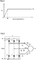
- inverter 4 includes at least six thyristors U, V, W, X, Y, and Z.
- Thyristors U, V, and W have anodes all connected to positive input terminal 4a and cathodes connected to output terminals 4c to 4e, respectively.
- Thyristors X, Y, and Z have anodes connected to output terminals 4c to 4e, respectively, and cathodes all connected to negative input terminal 4b.
- one thyristor of thyristors U, V, and W and one thyristor of thyristors X, Y, and Z are rendered conducting, so that three-phase AC power can be supplied to synchronous machine 21 and rotation speed N of synchronous machine 21 can be increased.
- Figs. 4(a) to (c) are timing charts schematically showing an ideal commutation operation of inverter 4.
- Fig. 4(a) shows three-phase AC voltages VR, VS, and VT
- Fig. 4(b) shows conducting thyristors among six thyristors U, V, W, X, Y, and Z of inverter 4
- Fig. 4(c) shows DC voltage VDC2 which appears across input terminals 4a and 4b of inverter 4.
- an ignition command signal is given to a prescribed thyristor. For example, an ignition command signal is provided to thyristor V while thyristor U is conducting, and then an ignition command signal is provided to thyristor W while thyristor V is conducting. Similarly, an ignition command signal is provided to thyristor X while thyristor Z is conducting, and then an ignition command signal is provided to thyristor Y while thyristor X is conducting.
- Control unit 10 controls a path for a current which flows through synchronous machine 21, by igniting two of six thyristors U, V, W, X, Y, and Z in an orderly sequence with rotation of synchronous machine 21, and achieves synchronization with rotation of synchronous machine 21.
- Figs. 5(a) and (b) are timing charts schematically showing an ideal commutation operation of inverter 4 when rotation speed N has increased, which are compared with Figs. 4(a) to (c) .
- Fig. 5(a) shows three-phase AC voltages VR, VS, and VT and
- Fig. 5(b) shows DC voltage VDC2 which appears across input terminals 4a and 4b of inverter 4.
- Figs. 5(a) and (b) even a case that rotation speed N of synchronous machine 21 increases is the same as in Figs. 4(a) to (c) , and an average value for DC voltage VDC2 is not varied.
- Fig. 6 (a) is a diagram showing relation between rotation speed N and DC voltage VDC2 in an ideal case
- Fig. 6(b) is a diagram showing relation between rotation speed N and phase control angle ⁇ in that case.
- a method of setting phase control angle ⁇ to a constant value is referred to as a ⁇ constant control scheme.
- arc suppression of a conducting thyristor does not instantaneously occur.
- Fig. 7 is a circuit diagram showing a current which actually flows in inverter 4 shown in Fig. 3 .
- synchronous machine 21 includes three-phase inductances 21r, 21s, and 21t.
- Figs. 8(a) to (c) are timing charts schematically showing an actual commutation operation of inverter 4, which are compared with Figs. 4(a) to (c) .
- Fig. 8(a) shows three-phase AC voltages VR, VS, and VT
- Fig. 8(b) shows conducting thyristors among six thyristors U, V, W, X, Y, and Z of inverter 4
- Fig. 8(c) shows DC voltage VDC2 which appears across input terminals 4a and 4b of inverter 4.
- Figs. 8(a) shows three-phase AC voltages VR, VS, and VT
- Fig. 8(b) shows conducting thyristors among six thyristors U, V, W, X, Y, and Z of inverter 4
- Fig. 8(c) shows DC voltage VDC2 which appears across input terminals 4a and 4b of inverter 4.
- DC voltage VDC2 is higher by an amount comparable to a hatched portion in the drawings than during a period in the ideal commutation operation.
- Figs. 9 (a) and (b) are timing charts schematically showing an actual commutation operation of inverter 4 in a case where rotation speed N has increased, which are compared with Figs. 8(a) to (c) .
- Fig. 9(a) shows three-phase AC voltages VR, VS, and VT and
- Fig. 9(b) shows DC voltage VDC2 which appears across input terminals 4a and 4b of inverter 4.
- a ratio of increase in DC voltage VDC2 during commutation is higher.
- Figs. 10(a) and (b) are diagrams showing actual relation among rotation speed N, phase control angle ⁇ , and DC voltage VDC2 in the y constant control scheme, and in particular, Fig. 10(a) shows relation between rotation speed N and DC voltage VDC2 and Fig. 10(b) shows relation between rotation speed N and phase control angle ⁇ .
- Figs. 10(a) and (b) when phase control angle ⁇ is actually maintained constant, due to the influence by increase in commutation overlap period, DC voltage VDC2 gradually increases with increase in rotation speed N. Since DC voltage VDC1 higher than DC voltage VDC2 should be supplied from converter 2, large converter 2 is required.
- a method of linearly increasing phase control angle ⁇ at a constant rate of increase ⁇ / ⁇ N from a minimum value to a maximum value with increase in rotation speed N is possible, which is referred to as a ⁇ linear control scheme here.
- Figs. 11(a) and (b) are timing charts schematically showing an actual commutation operation of inverter 4 in a case where phase control angle ⁇ is increased, which are compared with Figs. 8(a) to (c) .
- Fig. 11(a) shows three-phase AC voltages VR, VS, and VT and
- Fig. 11(b) shows DC voltage VDC2 which appears across input terminals 4a and 4b of inverter 4.
- phase control angle ⁇ is increased to ⁇ 1, ⁇ 2, ⁇ 3, ... (here, ⁇ 1 ⁇ 2 ⁇ 3)
- DC voltage VDC2 increases owing to commutation overlap angle u.
- phase control angle ⁇ is increased, however, as compared with a case where phase control angle ⁇ is not increased, DC voltage VDC2 is lowered by an amount of a hatched portion. Therefore, with the ⁇ linear control scheme, increase in DC voltage VDC2 with increase in rotation speed N can be corrected.
- Fig. 12(a) is a diagram showing relation between rotation speed N and DC voltage VDC2 in the ⁇ linear control scheme
- Fig. 12(b) is a diagram showing relation between rotation speed N and phase control angle ⁇ in that scheme.
- Figs. 12(a) and (b) in the ⁇ linear control scheme, when rotation speed N is between 0 and Na, phase control angle ⁇ is maintained at a minimum value ⁇ a.
- inverter 4 is controlled based on a signal output from voltage detector 7 or a rotor position signal output from a rotor position detector (not shown) provided in synchronous machine 21.
- phase control angle ⁇ is maintained at sufficiently small constant value ya regardless of rotation speed N.
- rotation speed N is between Na and Nb
- phase control angle ⁇ linearly increases from minimum value ya to a maximum value yb in accordance with rotation speed N.
- phase control angle ⁇ is maintained at maximum value yb.
- start of synchronous machine 21 by a thyristor starter ends and synchronous machine 21 is rotationally driven by a gas turbine.
- DC voltage VDC2 cannot evenly be lowered over the entire region of rotation speed N.
- DC voltage VDC2 non-linearly varies and has a peak value at certain rotation speed Np. Therefore, converter 2 having such a capacity as allowing output of DC voltage VDC1 even at the time when DC voltage VDC2 attains to a peak value should be provided.
- a converter 2 At rotation speed N other than rotation speed Np at which DC voltage VDC2 attains to a peak value, such a converter 2 should operate with DC voltage VDC1 being lowered, and efficiency in use of converter 2 lowers.
- rate of increase ⁇ / ⁇ N in phase control angle ⁇ is varied two or more times in accordance with rotation speed N such that DC voltage VDC2 is close to a constant value.
- this method is referred to as a y variable control scheme.
- rotation speed N exceeds Nb, phase control angle ⁇ is maintained at maximum value yb.
- relation of Na ⁇ Nm ⁇ Nb, ⁇ a ⁇ m ⁇ b, and A1>A2 are satisfied.
- the y variable control scheme can lower DC voltage VDC2 over the entire region of rotation speed N and DC voltage VDC2 can be close to a constant value.
- DC voltage VDC2 can be close to a constant value.
- DC voltage VDC2 can be close to a constant value. Therefore, reduction in size and improvement in efficiency in use of converter 2 can be achieved.
- synchronous machine 21 is a generator rotationally driven by a gas turbine in a thermal power station
- the embodiment is not limited thereto and synchronous machine 21 may be a synchronous machine used in a general industrial field.
- synchronous machine 21 may be a synchronous machine for a cooling blower in ironworks.
Landscapes
- Engineering & Computer Science (AREA)
- Power Engineering (AREA)
- Control Of Eletrric Generators (AREA)
- Inverter Devices (AREA)
- Control Of Ac Motors In General (AREA)
Claims (5)
- Démarreur à thyristor destiné à démarrer une machine synchrone (21), comprenant :un convertisseur (2) convertissant une première puissance à courant alternatif (CA) en une puissance à courant continu (CC) ;un onduleur (4) convertissant ladite puissance CC en une seconde puissance CA à une fréquence variable et fournissant la seconde puissance CA à ladite machine synchrone (21) ;une partie d'opération de vitesse (8) donnant une vitesse de rotation de ladite machine synchrone (21) ;une partie d'opération d'angle de commande (9) comprenant une fonction ou un tableau montrant la relation entre la vitesse de rotation de ladite machine synchrone (21) et un angle de commande de phase dudit onduleur (4) et donnant un angle de commande de phase possédant une valeur selon la vitesse de rotation de ladite machine synchrone (21) donnée par ladite partie d'opération de vitesse (8) ; etune unité de commande (10) commandant ledit onduleur (4) sur la base de l'angle de commande de phase donné par ladite partie d'opération d'angle de commande (9),ladite partie d'opération d'angle de commande (9) étant adaptée pour faire varier ledit angle de commande de phase à partir d'une valeur minimale jusqu'à une valeur maximale selon la vitesse de rotation de ladite machine synchrone (21), caractérisé en ce que la partie d'opération d'angle de commande (9) est adaptée pour faire varier un taux d'augmentation dudit angle de commande de phase par rapport à la vitesse de rotation de ladite machine synchrone (21) en une pluralité d'étapes selon la vitesse de rotation de ladite machine synchrone de sorte qu'une tension CC qui apparaît au niveau d'une borne d'entrée dudit onduleur (4) soit constante malgré la variation de la vitesse de rotation de ladite machine synchrone (21).
- Démarreur à thyristor selon la revendication 1, ladite vitesse d'augmentation dudit angle de commande de phase par rapport à la vitesse de rotation de ladite machine synchrone (21) diminuant en une pluralité d'étapes selon la vitesse de rotation de ladite machine synchrone (21).
- Démarreur à thyristor selon la revendication 1, comprenant un détecteur de tension (7) détectant une tension CA triphasée délivrée en sortie par ladite machine synchrone (21), ladite partie d'opération de vitesse (8) étant adaptée pour donner une vitesse de rotation de ladite machine synchrone (21) sur la base de la tension CA triphasée détectée par ledit détecteur de tension (7).
- Démarreur à thyristor selon la revendication 1, comprenant un détecteur de position détectant une position d'un rotor de ladite machine synchrone (21), ladite partie d'opération de vitesse (8) étant adaptée pour donner une vitesse de rotation de ladite machine synchrone (21) sur la base d'un résultat de détection par ledit détecteur de position.
- Démarreur à thyristor selon la revendication 1, ladite machine synchrone (21) étant un générateur d'une centrale thermique.
Applications Claiming Priority (1)
| Application Number | Priority Date | Filing Date | Title |
|---|---|---|---|
| PCT/JP2012/071792 WO2014033849A1 (fr) | 2012-08-29 | 2012-08-29 | Dispositif d'activation de thyristor |
Publications (3)
| Publication Number | Publication Date |
|---|---|
| EP2892149A1 EP2892149A1 (fr) | 2015-07-08 |
| EP2892149A4 EP2892149A4 (fr) | 2016-07-06 |
| EP2892149B1 true EP2892149B1 (fr) | 2020-12-16 |
Family
ID=50182699
Family Applications (1)
| Application Number | Title | Priority Date | Filing Date |
|---|---|---|---|
| EP12883614.5A Active EP2892149B1 (fr) | 2012-08-29 | 2012-08-29 | Dispositif d'activation de thyristor |
Country Status (4)
| Country | Link |
|---|---|
| US (1) | US20150236622A1 (fr) |
| EP (1) | EP2892149B1 (fr) |
| JP (1) | JP5918371B2 (fr) |
| WO (1) | WO2014033849A1 (fr) |
Families Citing this family (8)
| Publication number | Priority date | Publication date | Assignee | Title |
|---|---|---|---|---|
| WO2018235188A1 (fr) | 2017-06-21 | 2018-12-27 | 東芝三菱電機産業システム株式会社 | Dispositif de démarrage de thyristor |
| JP6781343B2 (ja) * | 2017-06-21 | 2020-11-04 | 東芝三菱電機産業システム株式会社 | サイリスタ起動装置 |
| EP3644493B1 (fr) | 2017-06-21 | 2023-04-26 | Toshiba Mitsubishi-Electric Industrial Systems Corporation | Dispositif de démarrage de thyristor |
| US11233466B2 (en) * | 2017-06-21 | 2022-01-25 | Toshiba Mitsubishi-Electric Industrial Systems Corporation | Thyristor starter |
| US11469692B2 (en) * | 2018-02-19 | 2022-10-11 | Toshiba Mitsubishi-Electric Industrial Systems Corporation | Thyristor starter |
| WO2020141569A1 (fr) | 2019-01-04 | 2020-07-09 | 東芝三菱電機産業システム株式会社 | Dispositif de démarrage de thyristor |
| JP7315799B1 (ja) | 2021-11-15 | 2023-07-26 | 東芝三菱電機産業システム株式会社 | サイリスタ起動装置 |
| CN118743151A (zh) * | 2023-01-11 | 2024-10-01 | 株式会社Tmeic | 马达驱动系统以及逆变器装置的控制方法 |
Family Cites Families (15)
| Publication number | Priority date | Publication date | Assignee | Title |
|---|---|---|---|---|
| JPS51129614A (en) * | 1975-05-06 | 1976-11-11 | Hitachi Ltd | Speed controller for no-commutator motor |
| JPS5953795B2 (ja) * | 1978-02-03 | 1984-12-26 | 株式会社日立製作所 | サイリスタモ−タの制御装置 |
| CA1244077A (fr) * | 1984-05-04 | 1988-11-01 | Akio Hirata | Inverseur commute par la charge pour faire fonctionner un moteur synchrone |
| US4870338A (en) * | 1988-09-26 | 1989-09-26 | Westinghouse Electric Corp. | Load commutated inverter (LCI) induction motor drive |
| JP3506457B2 (ja) * | 1993-04-23 | 2004-03-15 | 東芝キヤリア株式会社 | 空気調和機におけるコンプレッサの起動制御方法 |
| JP3052804B2 (ja) * | 1995-05-19 | 2000-06-19 | トヨタ自動車株式会社 | 原動機の始動装置および始動方法 |
| JPH09322599A (ja) * | 1996-06-03 | 1997-12-12 | Hitachi Ltd | サイリスタ起動装置を備えた発電装置 |
| US6605912B1 (en) * | 1998-06-25 | 2003-08-12 | Delphi Technologies, Inc. | Method for controlling a permanent magnet motor |
| KR100438598B1 (ko) * | 2001-06-29 | 2004-07-02 | 엘지전자 주식회사 | 센서리스 비엘디씨 모터를 채용한 세탁기의 운전제어방법 |
| JP2003061380A (ja) * | 2001-08-10 | 2003-02-28 | Toshiba Corp | 同期機のサイリスタ起動装置 |
| KR100645808B1 (ko) * | 2004-12-08 | 2006-11-23 | 엘지전자 주식회사 | 모터 제어방법 |
| WO2010038282A1 (fr) * | 2008-10-01 | 2010-04-08 | 東芝三菱電機産業システム株式会社 | Dispositif de démarrage de machine synchrone |
| WO2010086032A2 (fr) * | 2009-01-30 | 2010-08-05 | Siemens Aktiengesellschaft | Inertie fréquentielle du système d'énergie pour système de génération d'énergie |
| JP5514826B2 (ja) * | 2009-08-24 | 2014-06-04 | 東芝三菱電機産業システム株式会社 | 同期機起動装置 |
| JP2012135067A (ja) * | 2010-12-20 | 2012-07-12 | Hitachi Appliances Inc | 電動機の駆動装置 |
-
2012
- 2012-08-29 US US14/422,520 patent/US20150236622A1/en not_active Abandoned
- 2012-08-29 WO PCT/JP2012/071792 patent/WO2014033849A1/fr not_active Ceased
- 2012-08-29 JP JP2014532626A patent/JP5918371B2/ja active Active
- 2012-08-29 EP EP12883614.5A patent/EP2892149B1/fr active Active
Non-Patent Citations (1)
| Title |
|---|
| None * |
Also Published As
| Publication number | Publication date |
|---|---|
| JP5918371B2 (ja) | 2016-05-18 |
| US20150236622A1 (en) | 2015-08-20 |
| JPWO2014033849A1 (ja) | 2016-08-08 |
| EP2892149A1 (fr) | 2015-07-08 |
| WO2014033849A1 (fr) | 2014-03-06 |
| EP2892149A4 (fr) | 2016-07-06 |
Similar Documents
| Publication | Publication Date | Title |
|---|---|---|
| EP2892149A1 (fr) | Dispositif d'activation de thyristor | |
| US10033189B2 (en) | Operation control apparatus for solar power system | |
| JP6704523B2 (ja) | サイリスタ起動装置 | |
| EP3907879B1 (fr) | Dispositif de démarrage de thyristor | |
| CN110771031B (zh) | 晶闸管起动装置 | |
| US11239769B2 (en) | Thyristor starter | |
| US10615683B2 (en) | Method for controlling inverter | |
| JPWO2018235190A1 (ja) | サイリスタ起動装置 | |
| Banerjee et al. | Performance comparison of transfer switch topologies in switched-doubly-fed machine drives | |
| JPH0586152B2 (fr) | ||
| JP2012005303A (ja) | 直流電源装置 | |
| JPS59162797A (ja) | 巻線形誘導電動機のセルビウス制御による回転数制御装置 |
Legal Events
| Date | Code | Title | Description |
|---|---|---|---|
| PUAI | Public reference made under article 153(3) epc to a published international application that has entered the european phase |
Free format text: ORIGINAL CODE: 0009012 |
|
| 17P | Request for examination filed |
Effective date: 20150223 |
|
| AK | Designated contracting states |
Kind code of ref document: A1 Designated state(s): AL AT BE BG CH CY CZ DE DK EE ES FI FR GB GR HR HU IE IS IT LI LT LU LV MC MK MT NL NO PL PT RO RS SE SI SK SM TR |
|
| AX | Request for extension of the european patent |
Extension state: BA ME |
|
| DAX | Request for extension of the european patent (deleted) | ||
| RA4 | Supplementary search report drawn up and despatched (corrected) |
Effective date: 20160608 |
|
| RIC1 | Information provided on ipc code assigned before grant |
Ipc: H02P 1/46 20060101ALI20160602BHEP Ipc: H02P 27/06 20060101AFI20160602BHEP Ipc: H02P 27/16 20060101ALI20160602BHEP Ipc: H02P 9/08 20060101ALI20160602BHEP |
|
| STAA | Information on the status of an ep patent application or granted ep patent |
Free format text: STATUS: EXAMINATION IS IN PROGRESS |
|
| 17Q | First examination report despatched |
Effective date: 20191125 |
|
| GRAP | Despatch of communication of intention to grant a patent |
Free format text: ORIGINAL CODE: EPIDOSNIGR1 |
|
| STAA | Information on the status of an ep patent application or granted ep patent |
Free format text: STATUS: GRANT OF PATENT IS INTENDED |
|
| INTG | Intention to grant announced |
Effective date: 20200731 |
|
| GRAS | Grant fee paid |
Free format text: ORIGINAL CODE: EPIDOSNIGR3 |
|
| GRAA | (expected) grant |
Free format text: ORIGINAL CODE: 0009210 |
|
| STAA | Information on the status of an ep patent application or granted ep patent |
Free format text: STATUS: THE PATENT HAS BEEN GRANTED |
|
| AK | Designated contracting states |
Kind code of ref document: B1 Designated state(s): AL AT BE BG CH CY CZ DE DK EE ES FI FR GB GR HR HU IE IS IT LI LT LU LV MC MK MT NL NO PL PT RO RS SE SI SK SM TR |
|
| REG | Reference to a national code |
Ref country code: GB Ref legal event code: FG4D |
|
| REG | Reference to a national code |
Ref country code: IE Ref legal event code: FG4D |
|
| REG | Reference to a national code |
Ref country code: DE Ref legal event code: R096 Ref document number: 602012073786 Country of ref document: DE |
|
| REG | Reference to a national code |
Ref country code: AT Ref legal event code: REF Ref document number: 1346515 Country of ref document: AT Kind code of ref document: T Effective date: 20210115 |
|
| PG25 | Lapsed in a contracting state [announced via postgrant information from national office to epo] |
Ref country code: NO Free format text: LAPSE BECAUSE OF FAILURE TO SUBMIT A TRANSLATION OF THE DESCRIPTION OR TO PAY THE FEE WITHIN THE PRESCRIBED TIME-LIMIT Effective date: 20210316 Ref country code: FI Free format text: LAPSE BECAUSE OF FAILURE TO SUBMIT A TRANSLATION OF THE DESCRIPTION OR TO PAY THE FEE WITHIN THE PRESCRIBED TIME-LIMIT Effective date: 20201216 Ref country code: RS Free format text: LAPSE BECAUSE OF FAILURE TO SUBMIT A TRANSLATION OF THE DESCRIPTION OR TO PAY THE FEE WITHIN THE PRESCRIBED TIME-LIMIT Effective date: 20201216 Ref country code: GR Free format text: LAPSE BECAUSE OF FAILURE TO SUBMIT A TRANSLATION OF THE DESCRIPTION OR TO PAY THE FEE WITHIN THE PRESCRIBED TIME-LIMIT Effective date: 20210317 |
|
| REG | Reference to a national code |
Ref country code: AT Ref legal event code: MK05 Ref document number: 1346515 Country of ref document: AT Kind code of ref document: T Effective date: 20201216 |
|
| REG | Reference to a national code |
Ref country code: NL Ref legal event code: MP Effective date: 20201216 |
|
| PG25 | Lapsed in a contracting state [announced via postgrant information from national office to epo] |
Ref country code: BG Free format text: LAPSE BECAUSE OF FAILURE TO SUBMIT A TRANSLATION OF THE DESCRIPTION OR TO PAY THE FEE WITHIN THE PRESCRIBED TIME-LIMIT Effective date: 20210316 Ref country code: LV Free format text: LAPSE BECAUSE OF FAILURE TO SUBMIT A TRANSLATION OF THE DESCRIPTION OR TO PAY THE FEE WITHIN THE PRESCRIBED TIME-LIMIT Effective date: 20201216 Ref country code: SE Free format text: LAPSE BECAUSE OF FAILURE TO SUBMIT A TRANSLATION OF THE DESCRIPTION OR TO PAY THE FEE WITHIN THE PRESCRIBED TIME-LIMIT Effective date: 20201216 |
|
| PG25 | Lapsed in a contracting state [announced via postgrant information from national office to epo] |
Ref country code: NL Free format text: LAPSE BECAUSE OF FAILURE TO SUBMIT A TRANSLATION OF THE DESCRIPTION OR TO PAY THE FEE WITHIN THE PRESCRIBED TIME-LIMIT Effective date: 20201216 Ref country code: HR Free format text: LAPSE BECAUSE OF FAILURE TO SUBMIT A TRANSLATION OF THE DESCRIPTION OR TO PAY THE FEE WITHIN THE PRESCRIBED TIME-LIMIT Effective date: 20201216 |
|
| REG | Reference to a national code |
Ref country code: LT Ref legal event code: MG9D |
|
| PG25 | Lapsed in a contracting state [announced via postgrant information from national office to epo] |
Ref country code: RO Free format text: LAPSE BECAUSE OF FAILURE TO SUBMIT A TRANSLATION OF THE DESCRIPTION OR TO PAY THE FEE WITHIN THE PRESCRIBED TIME-LIMIT Effective date: 20201216 Ref country code: SK Free format text: LAPSE BECAUSE OF FAILURE TO SUBMIT A TRANSLATION OF THE DESCRIPTION OR TO PAY THE FEE WITHIN THE PRESCRIBED TIME-LIMIT Effective date: 20201216 Ref country code: PT Free format text: LAPSE BECAUSE OF FAILURE TO SUBMIT A TRANSLATION OF THE DESCRIPTION OR TO PAY THE FEE WITHIN THE PRESCRIBED TIME-LIMIT Effective date: 20210416 Ref country code: LT Free format text: LAPSE BECAUSE OF FAILURE TO SUBMIT A TRANSLATION OF THE DESCRIPTION OR TO PAY THE FEE WITHIN THE PRESCRIBED TIME-LIMIT Effective date: 20201216 Ref country code: SM Free format text: LAPSE BECAUSE OF FAILURE TO SUBMIT A TRANSLATION OF THE DESCRIPTION OR TO PAY THE FEE WITHIN THE PRESCRIBED TIME-LIMIT Effective date: 20201216 Ref country code: CZ Free format text: LAPSE BECAUSE OF FAILURE TO SUBMIT A TRANSLATION OF THE DESCRIPTION OR TO PAY THE FEE WITHIN THE PRESCRIBED TIME-LIMIT Effective date: 20201216 Ref country code: EE Free format text: LAPSE BECAUSE OF FAILURE TO SUBMIT A TRANSLATION OF THE DESCRIPTION OR TO PAY THE FEE WITHIN THE PRESCRIBED TIME-LIMIT Effective date: 20201216 |
|
| PG25 | Lapsed in a contracting state [announced via postgrant information from national office to epo] |
Ref country code: PL Free format text: LAPSE BECAUSE OF FAILURE TO SUBMIT A TRANSLATION OF THE DESCRIPTION OR TO PAY THE FEE WITHIN THE PRESCRIBED TIME-LIMIT Effective date: 20201216 Ref country code: AT Free format text: LAPSE BECAUSE OF FAILURE TO SUBMIT A TRANSLATION OF THE DESCRIPTION OR TO PAY THE FEE WITHIN THE PRESCRIBED TIME-LIMIT Effective date: 20201216 |
|
| REG | Reference to a national code |
Ref country code: DE Ref legal event code: R097 Ref document number: 602012073786 Country of ref document: DE |
|
| PG25 | Lapsed in a contracting state [announced via postgrant information from national office to epo] |
Ref country code: IS Free format text: LAPSE BECAUSE OF FAILURE TO SUBMIT A TRANSLATION OF THE DESCRIPTION OR TO PAY THE FEE WITHIN THE PRESCRIBED TIME-LIMIT Effective date: 20210416 |
|
| PLBE | No opposition filed within time limit |
Free format text: ORIGINAL CODE: 0009261 |
|
| STAA | Information on the status of an ep patent application or granted ep patent |
Free format text: STATUS: NO OPPOSITION FILED WITHIN TIME LIMIT |
|
| PG25 | Lapsed in a contracting state [announced via postgrant information from national office to epo] |
Ref country code: AL Free format text: LAPSE BECAUSE OF FAILURE TO SUBMIT A TRANSLATION OF THE DESCRIPTION OR TO PAY THE FEE WITHIN THE PRESCRIBED TIME-LIMIT Effective date: 20201216 Ref country code: IT Free format text: LAPSE BECAUSE OF FAILURE TO SUBMIT A TRANSLATION OF THE DESCRIPTION OR TO PAY THE FEE WITHIN THE PRESCRIBED TIME-LIMIT Effective date: 20201216 |
|
| 26N | No opposition filed |
Effective date: 20210917 |
|
| PG25 | Lapsed in a contracting state [announced via postgrant information from national office to epo] |
Ref country code: DK Free format text: LAPSE BECAUSE OF FAILURE TO SUBMIT A TRANSLATION OF THE DESCRIPTION OR TO PAY THE FEE WITHIN THE PRESCRIBED TIME-LIMIT Effective date: 20201216 Ref country code: ES Free format text: LAPSE BECAUSE OF FAILURE TO SUBMIT A TRANSLATION OF THE DESCRIPTION OR TO PAY THE FEE WITHIN THE PRESCRIBED TIME-LIMIT Effective date: 20201216 |
|
| PG25 | Lapsed in a contracting state [announced via postgrant information from national office to epo] |
Ref country code: SI Free format text: LAPSE BECAUSE OF FAILURE TO SUBMIT A TRANSLATION OF THE DESCRIPTION OR TO PAY THE FEE WITHIN THE PRESCRIBED TIME-LIMIT Effective date: 20201216 |
|
| REG | Reference to a national code |
Ref country code: CH Ref legal event code: PL |
|
| PG25 | Lapsed in a contracting state [announced via postgrant information from national office to epo] |
Ref country code: MC Free format text: LAPSE BECAUSE OF FAILURE TO SUBMIT A TRANSLATION OF THE DESCRIPTION OR TO PAY THE FEE WITHIN THE PRESCRIBED TIME-LIMIT Effective date: 20201216 |
|
| REG | Reference to a national code |
Ref country code: BE Ref legal event code: MM Effective date: 20210831 |
|
| PG25 | Lapsed in a contracting state [announced via postgrant information from national office to epo] |
Ref country code: LI Free format text: LAPSE BECAUSE OF NON-PAYMENT OF DUE FEES Effective date: 20210831 Ref country code: CH Free format text: LAPSE BECAUSE OF NON-PAYMENT OF DUE FEES Effective date: 20210831 |
|
| PG25 | Lapsed in a contracting state [announced via postgrant information from national office to epo] |
Ref country code: IS Free format text: LAPSE BECAUSE OF FAILURE TO SUBMIT A TRANSLATION OF THE DESCRIPTION OR TO PAY THE FEE WITHIN THE PRESCRIBED TIME-LIMIT Effective date: 20210416 Ref country code: LU Free format text: LAPSE BECAUSE OF NON-PAYMENT OF DUE FEES Effective date: 20210829 |
|
| PG25 | Lapsed in a contracting state [announced via postgrant information from national office to epo] |
Ref country code: IE Free format text: LAPSE BECAUSE OF NON-PAYMENT OF DUE FEES Effective date: 20210829 Ref country code: BE Free format text: LAPSE BECAUSE OF NON-PAYMENT OF DUE FEES Effective date: 20210831 |
|
| PG25 | Lapsed in a contracting state [announced via postgrant information from national office to epo] |
Ref country code: HU Free format text: LAPSE BECAUSE OF FAILURE TO SUBMIT A TRANSLATION OF THE DESCRIPTION OR TO PAY THE FEE WITHIN THE PRESCRIBED TIME-LIMIT; INVALID AB INITIO Effective date: 20120829 Ref country code: CY Free format text: LAPSE BECAUSE OF FAILURE TO SUBMIT A TRANSLATION OF THE DESCRIPTION OR TO PAY THE FEE WITHIN THE PRESCRIBED TIME-LIMIT Effective date: 20201216 |
|
| PG25 | Lapsed in a contracting state [announced via postgrant information from national office to epo] |
Ref country code: MK Free format text: LAPSE BECAUSE OF FAILURE TO SUBMIT A TRANSLATION OF THE DESCRIPTION OR TO PAY THE FEE WITHIN THE PRESCRIBED TIME-LIMIT Effective date: 20201216 |
|
| PG25 | Lapsed in a contracting state [announced via postgrant information from national office to epo] |
Ref country code: TR Free format text: LAPSE BECAUSE OF FAILURE TO SUBMIT A TRANSLATION OF THE DESCRIPTION OR TO PAY THE FEE WITHIN THE PRESCRIBED TIME-LIMIT Effective date: 20201216 |
|
| PG25 | Lapsed in a contracting state [announced via postgrant information from national office to epo] |
Ref country code: MT Free format text: LAPSE BECAUSE OF FAILURE TO SUBMIT A TRANSLATION OF THE DESCRIPTION OR TO PAY THE FEE WITHIN THE PRESCRIBED TIME-LIMIT Effective date: 20201216 |
|
| PGFP | Annual fee paid to national office [announced via postgrant information from national office to epo] |
Ref country code: DE Payment date: 20250702 Year of fee payment: 14 |
|
| PGFP | Annual fee paid to national office [announced via postgrant information from national office to epo] |
Ref country code: GB Payment date: 20250703 Year of fee payment: 14 |
|
| PGFP | Annual fee paid to national office [announced via postgrant information from national office to epo] |
Ref country code: FR Payment date: 20250703 Year of fee payment: 14 |