EP2894111A1 - Dispositif de capot et récipient pour couvrir une ouverture de canal de montage de vanne incorporée de récipient de vrac intermédiaire de type composite - Google Patents
Dispositif de capot et récipient pour couvrir une ouverture de canal de montage de vanne incorporée de récipient de vrac intermédiaire de type composite Download PDFInfo
- Publication number
- EP2894111A1 EP2894111A1 EP13835298.4A EP13835298A EP2894111A1 EP 2894111 A1 EP2894111 A1 EP 2894111A1 EP 13835298 A EP13835298 A EP 13835298A EP 2894111 A1 EP2894111 A1 EP 2894111A1
- Authority
- EP
- European Patent Office
- Prior art keywords
- cover
- side plate
- base
- cover body
- container
- Prior art date
- Legal status (The legal status is an assumption and is not a legal conclusion. Google has not performed a legal analysis and makes no representation as to the accuracy of the status listed.)
- Granted
Links
Images







Classifications
-
- B—PERFORMING OPERATIONS; TRANSPORTING
- B65—CONVEYING; PACKING; STORING; HANDLING THIN OR FILAMENTARY MATERIAL
- B65D—CONTAINERS FOR STORAGE OR TRANSPORT OF ARTICLES OR MATERIALS, e.g. BAGS, BARRELS, BOTTLES, BOXES, CANS, CARTONS, CRATES, DRUMS, JARS, TANKS, HOPPERS, FORWARDING CONTAINERS; ACCESSORIES, CLOSURES, OR FITTINGS THEREFOR; PACKAGING ELEMENTS; PACKAGES
- B65D19/00—Pallets or like platforms, with or without side walls, for supporting loads to be lifted or lowered
- B65D19/02—Rigid pallets with side walls, e.g. box pallets
- B65D19/06—Rigid pallets with side walls, e.g. box pallets with bodies formed by uniting or interconnecting two or more components
-
- B—PERFORMING OPERATIONS; TRANSPORTING
- B65—CONVEYING; PACKING; STORING; HANDLING THIN OR FILAMENTARY MATERIAL
- B65D—CONTAINERS FOR STORAGE OR TRANSPORT OF ARTICLES OR MATERIALS, e.g. BAGS, BARRELS, BOTTLES, BOXES, CANS, CARTONS, CRATES, DRUMS, JARS, TANKS, HOPPERS, FORWARDING CONTAINERS; ACCESSORIES, CLOSURES, OR FITTINGS THEREFOR; PACKAGING ELEMENTS; PACKAGES
- B65D43/00—Lids or covers for rigid or semi-rigid containers
- B65D43/14—Non-removable lids or covers
- B65D43/16—Non-removable lids or covers hinged for upward or downward movement
-
- B—PERFORMING OPERATIONS; TRANSPORTING
- B65—CONVEYING; PACKING; STORING; HANDLING THIN OR FILAMENTARY MATERIAL
- B65D—CONTAINERS FOR STORAGE OR TRANSPORT OF ARTICLES OR MATERIALS, e.g. BAGS, BARRELS, BOTTLES, BOXES, CANS, CARTONS, CRATES, DRUMS, JARS, TANKS, HOPPERS, FORWARDING CONTAINERS; ACCESSORIES, CLOSURES, OR FITTINGS THEREFOR; PACKAGING ELEMENTS; PACKAGES
- B65D19/00—Pallets or like platforms, with or without side walls, for supporting loads to be lifted or lowered
- B65D19/38—Details or accessories
-
- B—PERFORMING OPERATIONS; TRANSPORTING
- B65—CONVEYING; PACKING; STORING; HANDLING THIN OR FILAMENTARY MATERIAL
- B65D—CONTAINERS FOR STORAGE OR TRANSPORT OF ARTICLES OR MATERIALS, e.g. BAGS, BARRELS, BOTTLES, BOXES, CANS, CARTONS, CRATES, DRUMS, JARS, TANKS, HOPPERS, FORWARDING CONTAINERS; ACCESSORIES, CLOSURES, OR FITTINGS THEREFOR; PACKAGING ELEMENTS; PACKAGES
- B65D43/00—Lids or covers for rigid or semi-rigid containers
- B65D43/14—Non-removable lids or covers
- B65D43/22—Devices for holding in closed position, e.g. clips
-
- B—PERFORMING OPERATIONS; TRANSPORTING
- B65—CONVEYING; PACKING; STORING; HANDLING THIN OR FILAMENTARY MATERIAL
- B65D—CONTAINERS FOR STORAGE OR TRANSPORT OF ARTICLES OR MATERIALS, e.g. BAGS, BARRELS, BOTTLES, BOXES, CANS, CARTONS, CRATES, DRUMS, JARS, TANKS, HOPPERS, FORWARDING CONTAINERS; ACCESSORIES, CLOSURES, OR FITTINGS THEREFOR; PACKAGING ELEMENTS; PACKAGES
- B65D55/00—Accessories for container closures not otherwise provided for
- B65D55/02—Locking devices; Means for discouraging or indicating unauthorised opening or removal of closure
-
- B—PERFORMING OPERATIONS; TRANSPORTING
- B65—CONVEYING; PACKING; STORING; HANDLING THIN OR FILAMENTARY MATERIAL
- B65D—CONTAINERS FOR STORAGE OR TRANSPORT OF ARTICLES OR MATERIALS, e.g. BAGS, BARRELS, BOTTLES, BOXES, CANS, CARTONS, CRATES, DRUMS, JARS, TANKS, HOPPERS, FORWARDING CONTAINERS; ACCESSORIES, CLOSURES, OR FITTINGS THEREFOR; PACKAGING ELEMENTS; PACKAGES
- B65D55/00—Accessories for container closures not otherwise provided for
- B65D55/02—Locking devices; Means for discouraging or indicating unauthorised opening or removal of closure
- B65D55/14—Applications of locks, e.g. of permutation or key-controlled locks
-
- B—PERFORMING OPERATIONS; TRANSPORTING
- B65—CONVEYING; PACKING; STORING; HANDLING THIN OR FILAMENTARY MATERIAL
- B65D—CONTAINERS FOR STORAGE OR TRANSPORT OF ARTICLES OR MATERIALS, e.g. BAGS, BARRELS, BOTTLES, BOXES, CANS, CARTONS, CRATES, DRUMS, JARS, TANKS, HOPPERS, FORWARDING CONTAINERS; ACCESSORIES, CLOSURES, OR FITTINGS THEREFOR; PACKAGING ELEMENTS; PACKAGES
- B65D77/00—Packages formed by enclosing articles or materials in preformed containers, e.g. boxes, cartons, sacks or bags
- B65D77/04—Articles or materials enclosed in two or more containers disposed one within another
- B65D77/06—Liquids or semi-liquids or other materials or articles enclosed in flexible containers disposed within rigid containers
- B65D77/061—Liquids or semi-liquids or other materials or articles enclosed in flexible containers disposed within rigid containers the containers being mounted on a pallet
-
- B—PERFORMING OPERATIONS; TRANSPORTING
- B65—CONVEYING; PACKING; STORING; HANDLING THIN OR FILAMENTARY MATERIAL
- B65D—CONTAINERS FOR STORAGE OR TRANSPORT OF ARTICLES OR MATERIALS, e.g. BAGS, BARRELS, BOTTLES, BOXES, CANS, CARTONS, CRATES, DRUMS, JARS, TANKS, HOPPERS, FORWARDING CONTAINERS; ACCESSORIES, CLOSURES, OR FITTINGS THEREFOR; PACKAGING ELEMENTS; PACKAGES
- B65D88/00—Large containers
- B65D88/02—Large containers rigid
-
- B—PERFORMING OPERATIONS; TRANSPORTING
- B65—CONVEYING; PACKING; STORING; HANDLING THIN OR FILAMENTARY MATERIAL
- B65D—CONTAINERS FOR STORAGE OR TRANSPORT OF ARTICLES OR MATERIALS, e.g. BAGS, BARRELS, BOTTLES, BOXES, CANS, CARTONS, CRATES, DRUMS, JARS, TANKS, HOPPERS, FORWARDING CONTAINERS; ACCESSORIES, CLOSURES, OR FITTINGS THEREFOR; PACKAGING ELEMENTS; PACKAGES
- B65D88/00—Large containers
- B65D88/54—Large containers characterised by means facilitating filling or emptying
-
- B—PERFORMING OPERATIONS; TRANSPORTING
- B65—CONVEYING; PACKING; STORING; HANDLING THIN OR FILAMENTARY MATERIAL
- B65D—CONTAINERS FOR STORAGE OR TRANSPORT OF ARTICLES OR MATERIALS, e.g. BAGS, BARRELS, BOTTLES, BOXES, CANS, CARTONS, CRATES, DRUMS, JARS, TANKS, HOPPERS, FORWARDING CONTAINERS; ACCESSORIES, CLOSURES, OR FITTINGS THEREFOR; PACKAGING ELEMENTS; PACKAGES
- B65D2313/00—Connecting or fastening means
- B65D2313/04—Connecting or fastening means of magnetic type
-
- B—PERFORMING OPERATIONS; TRANSPORTING
- B65—CONVEYING; PACKING; STORING; HANDLING THIN OR FILAMENTARY MATERIAL
- B65D—CONTAINERS FOR STORAGE OR TRANSPORT OF ARTICLES OR MATERIALS, e.g. BAGS, BARRELS, BOTTLES, BOXES, CANS, CARTONS, CRATES, DRUMS, JARS, TANKS, HOPPERS, FORWARDING CONTAINERS; ACCESSORIES, CLOSURES, OR FITTINGS THEREFOR; PACKAGING ELEMENTS; PACKAGES
- B65D2519/00—Pallets or like platforms, with or without side walls, for supporting loads to be lifted or lowered
- B65D2519/00004—Details relating to pallets
- B65D2519/00258—Overall construction
- B65D2519/00283—Overall construction of the load supporting surface
- B65D2519/00288—Overall construction of the load supporting surface made of one piece
-
- B—PERFORMING OPERATIONS; TRANSPORTING
- B65—CONVEYING; PACKING; STORING; HANDLING THIN OR FILAMENTARY MATERIAL
- B65D—CONTAINERS FOR STORAGE OR TRANSPORT OF ARTICLES OR MATERIALS, e.g. BAGS, BARRELS, BOTTLES, BOXES, CANS, CARTONS, CRATES, DRUMS, JARS, TANKS, HOPPERS, FORWARDING CONTAINERS; ACCESSORIES, CLOSURES, OR FITTINGS THEREFOR; PACKAGING ELEMENTS; PACKAGES
- B65D2519/00—Pallets or like platforms, with or without side walls, for supporting loads to be lifted or lowered
- B65D2519/00004—Details relating to pallets
- B65D2519/00258—Overall construction
- B65D2519/00283—Overall construction of the load supporting surface
- B65D2519/00293—Overall construction of the load supporting surface made of more than one piece
-
- B—PERFORMING OPERATIONS; TRANSPORTING
- B65—CONVEYING; PACKING; STORING; HANDLING THIN OR FILAMENTARY MATERIAL
- B65D—CONTAINERS FOR STORAGE OR TRANSPORT OF ARTICLES OR MATERIALS, e.g. BAGS, BARRELS, BOTTLES, BOXES, CANS, CARTONS, CRATES, DRUMS, JARS, TANKS, HOPPERS, FORWARDING CONTAINERS; ACCESSORIES, CLOSURES, OR FITTINGS THEREFOR; PACKAGING ELEMENTS; PACKAGES
- B65D2519/00—Pallets or like platforms, with or without side walls, for supporting loads to be lifted or lowered
- B65D2519/00004—Details relating to pallets
- B65D2519/00258—Overall construction
- B65D2519/00313—Overall construction of the base surface
- B65D2519/00328—Overall construction of the base surface shape of the contact surface of the base
- B65D2519/00333—Overall construction of the base surface shape of the contact surface of the base contact surface having a stringer-like shape
-
- B—PERFORMING OPERATIONS; TRANSPORTING
- B65—CONVEYING; PACKING; STORING; HANDLING THIN OR FILAMENTARY MATERIAL
- B65D—CONTAINERS FOR STORAGE OR TRANSPORT OF ARTICLES OR MATERIALS, e.g. BAGS, BARRELS, BOTTLES, BOXES, CANS, CARTONS, CRATES, DRUMS, JARS, TANKS, HOPPERS, FORWARDING CONTAINERS; ACCESSORIES, CLOSURES, OR FITTINGS THEREFOR; PACKAGING ELEMENTS; PACKAGES
- B65D2519/00—Pallets or like platforms, with or without side walls, for supporting loads to be lifted or lowered
- B65D2519/00004—Details relating to pallets
- B65D2519/00547—Connections
- B65D2519/00577—Connections structures connecting side walls, including corner posts, to each other
- B65D2519/00582—Connections structures connecting side walls, including corner posts, to each other structures intended to be disassembled, i.e. collapsible or dismountable
-
- B—PERFORMING OPERATIONS; TRANSPORTING
- B65—CONVEYING; PACKING; STORING; HANDLING THIN OR FILAMENTARY MATERIAL
- B65D—CONTAINERS FOR STORAGE OR TRANSPORT OF ARTICLES OR MATERIALS, e.g. BAGS, BARRELS, BOTTLES, BOXES, CANS, CARTONS, CRATES, DRUMS, JARS, TANKS, HOPPERS, FORWARDING CONTAINERS; ACCESSORIES, CLOSURES, OR FITTINGS THEREFOR; PACKAGING ELEMENTS; PACKAGES
- B65D2519/00—Pallets or like platforms, with or without side walls, for supporting loads to be lifted or lowered
- B65D2519/00004—Details relating to pallets
- B65D2519/00547—Connections
- B65D2519/00636—Connections structures connecting side walls to the pallet
- B65D2519/00641—Structures intended to be disassembled
- B65D2519/00646—Structures intended to be disassembled by means of hinges
-
- B—PERFORMING OPERATIONS; TRANSPORTING
- B65—CONVEYING; PACKING; STORING; HANDLING THIN OR FILAMENTARY MATERIAL
- B65D—CONTAINERS FOR STORAGE OR TRANSPORT OF ARTICLES OR MATERIALS, e.g. BAGS, BARRELS, BOTTLES, BOXES, CANS, CARTONS, CRATES, DRUMS, JARS, TANKS, HOPPERS, FORWARDING CONTAINERS; ACCESSORIES, CLOSURES, OR FITTINGS THEREFOR; PACKAGING ELEMENTS; PACKAGES
- B65D2519/00—Pallets or like platforms, with or without side walls, for supporting loads to be lifted or lowered
- B65D2519/00004—Details relating to pallets
- B65D2519/00736—Details
- B65D2519/00805—Means for facilitating the removal of the load
-
- B—PERFORMING OPERATIONS; TRANSPORTING
- B65—CONVEYING; PACKING; STORING; HANDLING THIN OR FILAMENTARY MATERIAL
- B65D—CONTAINERS FOR STORAGE OR TRANSPORT OF ARTICLES OR MATERIALS, e.g. BAGS, BARRELS, BOTTLES, BOXES, CANS, CARTONS, CRATES, DRUMS, JARS, TANKS, HOPPERS, FORWARDING CONTAINERS; ACCESSORIES, CLOSURES, OR FITTINGS THEREFOR; PACKAGING ELEMENTS; PACKAGES
- B65D2519/00—Pallets or like platforms, with or without side walls, for supporting loads to be lifted or lowered
- B65D2519/00004—Details relating to pallets
- B65D2519/00736—Details
- B65D2519/00865—Collapsible, i.e. at least two constitutive elements remaining hingedly connected
- B65D2519/00875—Collapsible, i.e. at least two constitutive elements remaining hingedly connected collapsible side walls
- B65D2519/009—Collapsible, i.e. at least two constitutive elements remaining hingedly connected collapsible side walls whereby all side walls are hingedly connected to the base panel
-
- B—PERFORMING OPERATIONS; TRANSPORTING
- B65—CONVEYING; PACKING; STORING; HANDLING THIN OR FILAMENTARY MATERIAL
- B65D—CONTAINERS FOR STORAGE OR TRANSPORT OF ARTICLES OR MATERIALS, e.g. BAGS, BARRELS, BOTTLES, BOXES, CANS, CARTONS, CRATES, DRUMS, JARS, TANKS, HOPPERS, FORWARDING CONTAINERS; ACCESSORIES, CLOSURES, OR FITTINGS THEREFOR; PACKAGING ELEMENTS; PACKAGES
- B65D2588/00—Large container
- B65D2588/02—Large container rigid
- B65D2588/12—Large container rigid specially adapted for transport
- B65D2588/125—Intermediate bulk container [IBC]
Definitions
- the present invention relates to containers, in particular to dust-proof and thief-evident for a built-in valve mounting channel port of IBC.
- a cover is generally provided at the port of the valve mounting channel used to install a valve at the bottom of the container.
- the cover can achieve the effect of dust-proof to some extent.
- some of the known cover can not cover the port completely, resulting poor dust-proof.
- the cover at the channel port is flipped, the cover is not connected to any other elements, thus the operator needs to hold the cover while operating it, which is very inconvenient.
- the operator needs to put the cover back to the channel port manually, which reduces the operation efficiency.
- the channel port is opened, it occupies extra space of the IBC. Thus, if a forklift is used, the cover is easy to be damaged.
- covers in prior art used to cover the port of the valve mounting channel generally have no thief-evident feature since the cover can be opened directly.
- Some of the covers employ disposable plastic lids as their thief-evident features.
- Such plastic lid comprises three parts connected to each other through walls with unequal thicknesses, wherein the middle part is a tearable part, each of the other two parts at two sides has a snap snapping at the valve mounting channel port. The operator tears up the middle part of the plastic cover at first, and then disengages the snap from the valve mounting channel port at both sides when opening the cover, which is very inconvenient.
- a general tool can be used to disengage the snap of the plastic lid at both sides.
- the middle part will not be damaged or torn, and the intact cover will be removed due to the plasticity of the plastic itself, resulting poor thief-evident effect.
- the cover can not be reused, thereby increasing the cost.
- the fitting part located at the valve mounting channel port may be damaged while tearing the plastic lid.
- the object of the present invention is to provide a cover device used to cover a built-in valve mounting channel port of IBC, and the cover device is easy to operate and can well achieve the effect of dust-proof and/or thief-evident.
- the present invention provides a cover device used to cover a built-in valve mounting channel port of IBC, said IBC comprises a side plate, a base and a channel located in said base and used to receive the built-in valve, characterized in that:
- said cover is a plate member, comprising a fitting part and a cover body, wherein said rotational axis is located between said fitting part and said cover body, so that said cover body can be rotated around said rotational axis; fitting pins used to assemble said cover to said base are provided at the left and right sides of the fitting part respectively; and a structure used to be detachably engaged with the side plate is provided on said cover body, and a mating structure corresponding to said structure on said cover body is provided at the side plate.
- said structure on the cover body detachably engaged with the side plate are locking slots located at the left and right sides respectively; said mating structure on the side plate are grooves and ribs on both sides of said grooves respectively; and said locking slots can be engaged with said ribs under elastic deformation, so as to keep said cover on said side plate, and said locking slots can be disengaged from said ribs so as to disengage said cover from said side plate.
- said structure on said cover body detachably engaged with the side plate comprises a locking snap projecting integrally from said cover body surface; said corresponding structure on said side plate is a snap hole on said side plate; and said locking snap can be snapped into said snap hole so as to keep said cover on said side plate, and said locking snap can be disengaged from said snap hole so that said cover is disengaged from said side plate.
- said structure on said cover body detachably engaged with the side plate is a metal piece; said corresponding structure on said side plate is a magnet; and said metal piece and said magnet can be attracted to or separated from each other so as to respectively keep said cover on the side plate and disengage said cover from said side plate.
- a rotating part is provided between said fitting part and said cover body, wherein said fitting part, rotating part and said cover body are integrally formed; and the thickness of said rotating part is thinner than that of said fitting part and said cover body, so that when said cover body is flipped upward, said cover body is rotated around said rotating part.
- said fitting part is provided with hinge holes
- said cover body is provided with hinge pins, wherein said hinge holes and said hinge pins constitute hinges so that after said fitting part being assembled to said cover body, when said cover body is flipped upward, said cover body is rotated around said hinges.
- the present invention further provides a cover device used to cover a built-in valve mounting channel port of IBC, said container comprises a side plate, a base and a channel located in said base and used to receive the built-in valve, characterized in that: said cover device comprises a cover and structures or components used to detachably connect said cover to said side plate over said channel; said cover can be installed on said base at the position adjacent to said side plate, and can be rotated around the rotational axis of the cover itself, so as to open or cover said channel port; and said cover is further provided with a lock hole, and said base is provided with a locking slot, so that said cover can be locked to said base by a disposable lock.
- the cover body is further provided with a metal piece at the lower part thereof and said base is provided with a magnet, so that the metal piece and the magnet can be attracted to or disengaged from each other so as to keep said cover on said base or disengage said cover from said base.
- the present invention also provides a intermediate bulk container (IBC), said container comprises a side plate, a base and a channel located in said base and used to receive the built-in valve, wherein said container further comprises said cover device according to embodiments described above.
- IBC intermediate bulk container
- the cover device of the present invention used to cover the built-in valve mounting channel port of IBC has a simple structure and is easy to operate.
- the shape of the cover device corresponds to the channel port of the channel used to receive the built-in valve, and therefore has a good dust-proof effect.
- the cover device can be engaged with a disposable lock to achieve a good thief-evident effect. Besides, the cover device can be reused, thereby saving the cost.
- IBC Intermediate Bulk Container
- IBC containers can save about 35% of the storage space, and the dimensions thereof conform to ISO standards.
- IBC is not only suitable for aseptic filling but also has compact structure, and is convenient to store large quantities of goods with safety and efficiency, thus they are widely used in transportation, package, storage for materials in the form of liquid, particles and flakes.
- 820L, 1000L, 1250L for IBC which usually comprises a plastic liner, a filling port, a discharge valve, side plates, a base and a cover plate.
- IBC should has the function of preventing unauthorized opening or discharge during use.
- Figures 1-9 show the first embodiment of a cover device 100 for covering a built-in valve mounting channel port of IBC.
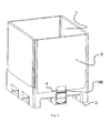
- Figure 1 shows an IBC 1 provided with the cover device 100 of the present invention.
- container 1 comprises a side plate 2, a base 3, a valve mounting channel 31 provided at the base 3 and used to receive the valve, a cover device 100 used to cover the port 32 of valve mounting channel.
- Cover device 100 comprises a cover 4 and structures provided at container 1 and engaged with the cover 4, so that when the cover 4 is closed, the valve mounting channel port 32 can be completely covered, thereby preventing dust and other foreign matter from entering the valve mounting channel.
- cover 4 When cover 4 is opened, the cover may be held on the side plate 2, so that the operator does not need to hold the cover while operating the valve. Also, when the cover is put down, it will automatically cover the mounting channel port 32, which will be further described hereinafter.
- FIG. 2 shows a structural perspective view of the cover 4 of the cover device 100 according to the present invention.
- the cover 4 is a plate member, including a fitting part and a cover body.
- the shape of the cover 4 can be designed according to the specific shape of the valve mounting channel port.
- Fitting part 40 of the cover 4 i.e., the upper portion of the plate member
- fitting pins 42 used to assemble the cover 4 to the base 3 at its left and right sides, wherein fitting pins 42 can be circular pins, or pins of any other suitable shapes.
- the cover can be assembled to the base by snaps, pivots, screws and so on.
- a rotating part 43 is provided between the fitting part 40 of the cover 4 and cover body 41, so that the cover body 41 can be rotated around the rotating part 43.
- the thickness of the rotating part 43 is thinner than that of the fitting part 40 and that of the body 41, so that when the cover body 41 is flipped upward, the body 41 is rotated around rotating part 43.
- Locking slots 46 are provided at left and right sides at the substantially intermediate position of the cover body 41 respectively, and are used to be engaged with ribs on the side plate 2 (described in detail hereinafter) respectively when the cover 4 is opened, so as to lock the cover 4 to the side plate 2.
- a metal piece 5 is provided at the lower part of cover body 41 and may be molded integrally with cover body 41, thereby locking the cover when the cover 4 is closed due to magnetic attraction between the metal piece 5 and the magnet provided on base of the container.
- the metal piece 5 can be made of any metal attractable to magnet, such as iron, cobalt, nickel and other materials. Also, it can be still a magnet.
- the metal piece is a magnet.
- a locking hole 45 is provided at an appropriate place (in this embodiment, above metal piece 5) on the cover body 41. The locking hole 45 is used to be engaged with the disposable lock so as to lock the cover 4 to the container. When there is a need to open the cover 4, the disposable lock should be destroyed at first. Only in this way, will the cover be opened, thereby achieving thief-evident, which will be described in detail hereinafter.
- Figure 3 illustrates an exploded perspective view of the container in Fig. 1 , for clarity, only the parts associated with the cover device of the present invention are shown here.
- grooves 33 are provided at the upper edge of the base 3 of the container above the valve mounting channel 31 and contacting with side plate 2. Grooves 33 are used to receive fitting pins 42 of the cover 4, so as to assemble the cover 4 to the base 3.
- the side plate 2 is put down, and then the fitting pin 42 is inserted into groove 33. After the side plate is erected up, the side plate 2 limits the position of the fitting pins 42 and hides them, so that the cover can not escape from container 1.
- the side plate 2 limits the position of the fitting pins 42 and hides them, so that the cover can not escape from container 1.
- a groove 34 (more clearly illustrated in Figure 5b ) used to receive the magnet 6 is provided at the base 3 under the valve mounting channel 31.
- the position of the groove 34 corresponds to that of the metal piece 5 of the installed cover 4, so that the magnet 6 and the metal pieces 5 can attract each other, thereby keeping the cover 4 covering the valve mounting channel port 31.
- a locking groove 36 (more clearly shown in Figure 9 ) is further provided at the base 3.
- the position of the locking groove 36 corresponds to that of the locking hole 45 on the installed cover 4, so that a disposable lock 7 (shown in Figures 9a-9c ) can pass though the locking hole 45, enter and snap in the locking groove 36, thereby locking the cover 4 to the container.
- a pit 21 is provided at the side plate 2.
- the ribs 22 are provided at both sides of the pit 21.
- Figure 4 is a perspective view of the container, in which the cover 4 is closed.
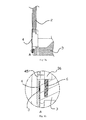
- Figures 5a-5b show relative positions of components of the cover device 100, wherein the cover 4 is closed.
- the cover 4 is in a closed state, and the locking hole 45 is aligned to the locking groove 36.
- the magnet 6 is received in groove 34.
- the center of metal piece 5 and the center of the magnet 6 are on substantially the same straight line, so that the metal piece 5 and the magnet 6 can effectively attract to each other, thus securely locking the cover 4.
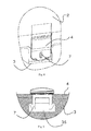
- Figures 6a-6b show sectional views of the container, wherein the cover 4 of which is open, for clarity, only the structures associated with the present invention are shown here.
- the cover body 41 can be rotated around the rotating part 42 and can be held on the side plate 2 through the engagement of the locking slots 46 on cover 4 with the ribs 22 on side plate 2.
- the cover when side plate 2 falls down, the cover will be automatically disengaged from side plate 2 and flipped downward due to gravity and elasticity, then cover the valve mounting channel port 32 through the interaction (magnetic attraction) between the metal piece 5 and the magnet 6.
- Figures 7a-7c show one embodiment of a disposable lock used in the cover device of the present invention. It should be understood that those skilled in the art may also use any other suitable disposable lock.
- lock 7 comprises a handle 71, a tear part 72 and an elastic snap 73.
- the handle 71, the tear part 72 and the elastic snap 73 are formed as one piece.
- the handle 71 is a plate member and is connected to the elastic snap 73 through the tear part 72.
- the tear part 72 is a portion easy to be torn.
- the tear part comprises two thin rods connecting the handle71 to the elastic snap 73.
- FIGs 8-9 show a schematic structural view of the cover device100 provided with the disposable lock 7 shown in Figures 7a-7c .
- the snap 73 on the lock 7 will be snapped into the locking groove 36 on the base 3, thereby locking the cover 4 to the base 3.
- you need to open the cover 4 at first pull the lock 7 forcefully, so that the tear part 72 on lock 7 is broken, thereby opening the door 4.
- FIG. 10-15b shows the second embodiment of the cover device 100 used to cover a built-in valve mounting channel port of IBC.
- Figure 10 shows a partially structural view of the IBC 1 provided with the cover device 100 of the present invention.
- the container comprises a side plate 2, a base 3, a valve mounting channel 31 provided at the base 3 and used to receive the valve, and a cover device 100 used to cover the valve mounting channel port 32.
- Cover device 100 comprises a cover 4 and structures provided on the container 1 and engaged with the cover 4, so that when cover 4 is closed, the valve mounting channel port 32 can be completely covered so as to prevent dust and other foreign matter from entering the valve mounting channel.
- the cover 4 When the cover 4 is opened, the cover can be held on the side plate 2 so that the operator does not need to hold the cover while operating the valve. When the cover is put down, it will automatically cover the valve mounting channel port 32, which will be described in more detail hereinafter.
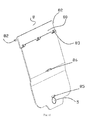
- FIG 11 shows a perspective structural view of the cover 8 of the cover device 100 of the present invention.
- the cover 8 is a plate member, the shape of which can be designed according to the specific shape of the valve mounting channel port.
- the cover 8 comprises a fitting part 80 and a body 81, wherein the fitting part 80 and the body 81 are connected with each other by a hinge 83 which is comprised of hinge holes located on the fitting part and hinge pins located on the body 81.
- the body 81 is rotated around the hinge 83 (as a rotational axis) when the body 81 is flipped upward.
- the fitting part 80 is integrally provided with fitting pins 82 used to assemble the cover 8 to the base 3 at the left and right sides respectively.
- the fitting pins 82 may be circular pins, or pins of any other suitable shape.
- a cover locking snap 86 projecting integrally from the surface of the cover body is provided at the middle of the cover body 81.
- the cover locking snap 86 will be engaged with a snap hole on side plate 2 so that the cover 8 is locked to side plate 2 after the cover is opened, which will be further described hereinafter.
- a metal piece 5 is provided at the lower part of the cover body 81.
- the metal piece 5 may be molded integrally with the cover body 81 so as to lock the cover (when cover 8 is closed) due to the magnetic attraction between the metal piece 5 and the magnet provided on the base of the container.
- the metal piece 5 can be made of metals attractable to the magnet, such as iron, cobalt, nickel and other materials. Also, it can be a magnet.
- the metal piece is a magnet.
- a locking hole 85 is provided at an appropriate place (in this embodiment, above metal piece 5) on the cover body 81. The locking hole 85 is used to be engaged with the disposable lock so as to lock the cover 8 to the container. When there is a need to open the cover 8, the disposable lock should be destroyed at first. Only in this way, will the cover be opened, thereby achieving thief-evident, which will be described in detail hereinafter.
- Figure 12 illustrates an exploded perspective view of the container in Fig. 10 , for clarity, only the parts associated with the cover device of the present invention is shown here.
- grooves 33 are provided at the upper edge of the base 3 of the container above the valve mounting channel 31 and contacting with side plate 2. Grooves 33 are used to receive fitting pins 82 of cover 8, so as to assemble the cover 8 to base 3.
- the fitting part 80 and the body 81 are assembled together, then the side plate 2 is put down, and the fitting pin 82 is inserted into the groove 33.
- the side plate 2 limits the position of fitting pins 82, so that the cover could not escape from container 1, and the fitting part 80 could not rotate around the fitting pins 82.
- the cover could not escape from container 1, and the fitting part 80 could not rotate around the fitting pins 82.
- a groove 34 (more clearly illustrated in Figure 14b ) used to receive magnet 6 is provided at the base 3 under the valve mounting channel 31.
- the position of the groove 34 corresponds to that of the metal piece 5 of the installed cover 8, so that magnet 6 and metal pieces 5 can attract with each other, thereby keeping the cover 8 covering the valve mounting channel port 31.
- a locking groove 36 (more clearly shown in Figure 9 ) is further provided at the base 3.
- the position of the locking groove 36 corresponds to that of the locking hole 85 on the installed cover 8, so that a disposable lock 7 (shown in Figures 9a-9c ) can pass though the locking hole 45, enter and snap in locking groove 36, thereby locking the cover 8 to the container.
- a snap hole 25 is provided at the side plate 2.
- the locking snap 86 on the cover 8 can snap into the snap hole 25 in order to keep the cover 8 on the side plate 2.
- Figure 13 is a partially perspective view of the container 1, in which the cover 8 is closed.
- Figures 14a-14b show relative positions of components of the cover device 100 when the cover 8 is closed.
- the cover 8 is in a closed state, and the locking hole 85 is aligned to the locking groove 36.
- the magnet 6 is received in the groove 34.
- the center of the metal piece 5 and the center of the magnet 6 are in substantially the same straight line, so that the metal piece 5 and the magnet 6 can effectively attract to each other, thus securely locking the cover 8.
- Figures 15a-15b show sectional views of the container when cover 8 of which is opened, for clarity, only the structures associated with the present invention are shown here. As shown in Figures 15a-15b , after door 8 is opened, the cover body 81 can be rotated around the hinge 83 and can be held on the side plate 2 through the engagement of the locking snap 86 on cover 4 with the locking hole 25 on side plate 2.
- the disposable lock 7 shown in Figures 7a-7c or other suitable disposable locks may be used to achieve the thief-evident effect.
- the disposable lock 7 is connected to the cover 8 and the base 3 in the same manner as that of the first embodiment, which will not be elaborated here.
- security code can be printed on the disposable lock 7 to obtain improved thief-evident effect.
- FIGS 16-18b show the third embodiment of the cover device used to cover the built-in valve mounting channel port of IBC.
- the embodiment is similar to the second embodiment except that the structure used to keep the cover 4 on the side plate 2 when the cover is opened, thus the same features will not be elaborated herein.
- the structures that keeps the cover 4 on the side plate comprise the snap 86 located on the cover body 81 and the snap hole 25 located on side plate 2. While in this embodiment, as shown in Figures 16-17 , the structures that keeps the cover 4 on the side plate comprise a metal piece 9 located in the cover body 81 and another magnet 10 located in the side plate 2.
- the metal piece 9 is positioned at an appropriate place in the cover body 81, and in this embodiment, the metal piece 9 is located substantially at the center of the body 81.
- the metal piece 9 can be made of metals attractable to magnet, such as iron, cobalt, nickel and other materials. Also, it can be a magnet. Preferably, the metal piece 9 is a magnet.
- the magnet 10 may be integrally molded to the side plate at the position corresponding to that of the metal piece 9 when the cover 4 is flipped upward and is substantially parallel to the side plate 2.
- a groove used to receive the magnet 10 can also be provided at the side plate 2.
- Figures 18a-18b show sectional views of the container, wherein the cover 8 is opened, and for clarity, only the structures associated with the present invention are shown here.
- the cover body 81 can be rotated around the hinge 83 and can eventually be kept on the side plate 2 through the mutual attraction between the metal piece 9 on the cover 8 and the magnet 10 on the side plate 2.
- the disposable lock 7 shown in Figures 7a-7c or other suitable disposable locks may be used to achieve the thief-evident effect.
- the disposable lock 7 is connected to the cover 8 and the base 3 in the same manner as that of the first embodiment, which will not be elaborated here.
- security code can be printed on the disposable lock 7 to obtain improved thief-evident effect.
- the locations of the metal piece and the magnet are interchangeable, i.e., the metal piece is provided at the corresponding position of the container, while the magnet is provided on the cover.
- magnets can be provided at both sides, and the shapes of the metal piece and the magnet can be determined as desired.
- the cover is preferably made of plastic material of better toughness.
- the cover device used to cover the built-in valve mounting channel port of IBC has a simple structure and is easy to operate.
- the shape of the cover device corresponds to that of the channel port of the channel used to receive the built-in valve, and therefore has a good dust-proof effect. Further, the cover device can be reused, thereby saving cost.
Landscapes
- Engineering & Computer Science (AREA)
- Mechanical Engineering (AREA)
- Closures For Containers (AREA)
- Laying Of Electric Cables Or Lines Outside (AREA)
Applications Claiming Priority (2)
| Application Number | Priority Date | Filing Date | Title |
|---|---|---|---|
| CN201210324749.2A CN102785829B (zh) | 2012-09-04 | 2012-09-04 | 用于遮盖复合型中型散装容器中内置阀门安装通道口的盖装置及容器 |
| PCT/CN2013/082931 WO2014036941A1 (fr) | 2012-09-04 | 2013-09-04 | Dispositif de capot et récipient pour couvrir une ouverture de canal de montage de vanne incorporée de récipient de vrac intermédiaire de type composite |
Publications (3)
| Publication Number | Publication Date |
|---|---|
| EP2894111A1 true EP2894111A1 (fr) | 2015-07-15 |
| EP2894111A4 EP2894111A4 (fr) | 2016-03-16 |
| EP2894111B1 EP2894111B1 (fr) | 2017-06-28 |
Family
ID=47151446
Family Applications (1)
| Application Number | Title | Priority Date | Filing Date |
|---|---|---|---|
| EP13835298.4A Active EP2894111B1 (fr) | 2012-09-04 | 2013-09-04 | Récipient pour matières en vrac comportant un dispositif de recouvrement |
Country Status (4)
| Country | Link |
|---|---|
| US (1) | US9731873B2 (fr) |
| EP (1) | EP2894111B1 (fr) |
| CN (1) | CN102785829B (fr) |
| WO (1) | WO2014036941A1 (fr) |
Cited By (4)
| Publication number | Priority date | Publication date | Assignee | Title |
|---|---|---|---|---|
| CN107585436A (zh) * | 2017-09-13 | 2018-01-16 | 湖州创通输送设备有限公司 | 一种液体运输用运输装置 |
| EP3733549A1 (fr) * | 2019-04-30 | 2020-11-04 | Schoeller Allibert GmbH | Récipient pourvu de couvercle autoportant pour la sortie |
| CN111902344A (zh) * | 2018-01-18 | 2020-11-06 | 舒乐埃丽伯特有限公司 | 具有阀组件的容器 |
| EP4101781A4 (fr) * | 2020-02-03 | 2024-03-13 | Shanghai Hongyan Returnable Transit Packagings Co., Ltd. | Conteneur |
Families Citing this family (14)
| Publication number | Priority date | Publication date | Assignee | Title |
|---|---|---|---|---|
| CN102785829B (zh) * | 2012-09-04 | 2014-11-05 | 上海鸿研物流技术有限公司 | 用于遮盖复合型中型散装容器中内置阀门安装通道口的盖装置及容器 |
| US9487326B2 (en) * | 2013-11-26 | 2016-11-08 | Orbis Corporation | Bulk bin with panel to panel interlock features |
| CN104882873B (zh) * | 2015-05-22 | 2018-09-28 | 东阳市阳涛电子科技有限公司 | 电源防雷箱 |
| USD809995S1 (en) * | 2016-08-18 | 2018-02-13 | Ford Motor Company | Sensor cover |
| USD838231S1 (en) | 2016-08-18 | 2019-01-15 | Ford Motor Company | Sensor cover |
| USD838230S1 (en) | 2016-08-18 | 2019-01-15 | Ford Motor Company | Sensor cover |
| US10527464B2 (en) | 2016-08-18 | 2020-01-07 | Ford Global Technologies, Llc | Rotatable sensor cover |
| ES2912462T3 (es) * | 2017-12-06 | 2022-05-26 | Vitop Moulding Srl | Grifo de distribución provisto con una válvula de silicona interna con sistemas de estanqueidad a líquidos y de prevención de manipulación |
| CN108839953B (zh) * | 2018-08-23 | 2023-09-29 | 上海箱箱智能科技有限公司 | 周转容器 |
| CN110329643B (zh) * | 2019-06-13 | 2021-05-11 | 江西奕方农业科技有限公司 | 包装装置及其包装方法 |
| CN112911890B (zh) * | 2019-11-19 | 2022-04-22 | 英业达科技有限公司 | 风扇架 |
| CN112124741B (zh) * | 2020-09-14 | 2025-06-27 | 中国国际海运集装箱(集团)股份有限公司 | 托盘箱 |
| CN113006600A (zh) * | 2021-03-24 | 2021-06-22 | 上海箱箱智能科技有限公司 | 锁扣装置、锁具和容器 |
| CN114735346A (zh) * | 2022-04-15 | 2022-07-12 | 深圳中集易租科技有限公司 | 用于容器排料口的通道盖装置以及容器 |
Family Cites Families (27)
| Publication number | Priority date | Publication date | Assignee | Title |
|---|---|---|---|---|
| US2271660A (en) * | 1938-01-04 | 1942-02-03 | Nat Fitch Corp | Demountable freight container for liquids |
| US4366915A (en) * | 1980-09-17 | 1983-01-04 | Revlon Inc. | Hinged lid container |
| US4711372A (en) * | 1987-02-02 | 1987-12-08 | Sunbeam Plastics Corporation | Tamper indicating closure |
| US4809875A (en) * | 1987-11-30 | 1989-03-07 | Yazaki Corporation | Electrical component container having improved hinge unit |
| US4949865A (en) * | 1990-01-02 | 1990-08-21 | Williams Industries, Inc. | Container lid with integral stopper |
| DE4206945C1 (fr) * | 1991-03-15 | 1993-03-11 | Schuetz-Werke Gmbh & Co. Kg, 5418 Selters, De | |
| GB2273488B (en) | 1992-12-17 | 1996-03-06 | Flomotion Ltd | Bulk container with removable tray |
| GB2297740A (en) | 1995-02-10 | 1996-08-14 | Peter Jeffrey Farrell | Container apparatus for fluid materials |
| US5893475A (en) * | 1997-04-16 | 1999-04-13 | Sprintquip Nz Limited | Tamper proof container |
| DE19720931C2 (de) * | 1997-05-20 | 1999-12-02 | Protechna Sa | Transport- und Lagerbehälter für Flüssigkeiten |
| AUPO965097A0 (en) | 1997-10-08 | 1997-10-30 | Technosearch Pty. Limited | Improvements in containers |
| ATE234228T1 (de) * | 1998-11-25 | 2003-03-15 | Carrimor | Zusammenklappbarer behälter zur aufnahme von flüssigen substanzen |
| DE19958491C1 (de) * | 1999-12-04 | 2001-05-10 | Protechna Sa | Transport- und Lagerbehälter für Flüssigkeiten |
| US6533122B1 (en) * | 2000-02-07 | 2003-03-18 | James Plunkett | Shipping container |
| US20020130128A1 (en) * | 2001-03-02 | 2002-09-19 | Bruce Berglund | Magnetically sealable enlosure |
| FR2830000A1 (fr) | 2001-09-26 | 2003-03-28 | Log6 | Conteneur |
| CN100400388C (zh) * | 2001-11-13 | 2008-07-09 | 达特食品容器公司 | 具有密封塞的可再封闭盖 |
| US7861877B2 (en) | 2006-03-31 | 2011-01-04 | Custom Metalcraft, Inc. | Foldable container |
| KR20060040650A (ko) | 2006-04-21 | 2006-05-10 | 백영자 | 마개 분실방지 용기 |
| CN201105852Y (zh) | 2007-09-30 | 2008-08-27 | 杜壮锋 | 一种通配性好的杯盖 |
| JP5444741B2 (ja) * | 2008-03-03 | 2014-03-19 | パナソニック株式会社 | 電子機器 |
| KR20100008131A (ko) | 2008-07-15 | 2010-01-25 | 조제복 | 캡수용부가 구비된 음료수 용기 |
| CN201553333U (zh) | 2009-06-26 | 2010-08-18 | 陕西秦川机械发展股份有限公司 | 更易成型的集装桶 |
| CN202115803U (zh) | 2011-04-27 | 2012-01-18 | 江阴康爱特包装有限公司 | 安全性高的中型散装容器 |
| AU2012100058A4 (en) * | 2012-01-19 | 2012-03-08 | Flextank, Inc. | Intermediate bulk container assemblies |
| CN202987819U (zh) | 2012-09-04 | 2013-06-12 | 上海鸿润科技有限公司 | 用于遮盖中型散装容器中阀门安装通道口的盖装置及容器 |
| CN102785829B (zh) | 2012-09-04 | 2014-11-05 | 上海鸿研物流技术有限公司 | 用于遮盖复合型中型散装容器中内置阀门安装通道口的盖装置及容器 |
-
2012
- 2012-09-04 CN CN201210324749.2A patent/CN102785829B/zh active Active
-
2013
- 2013-09-04 WO PCT/CN2013/082931 patent/WO2014036941A1/fr not_active Ceased
- 2013-09-04 US US14/425,508 patent/US9731873B2/en active Active
- 2013-09-04 EP EP13835298.4A patent/EP2894111B1/fr active Active
Cited By (10)
| Publication number | Priority date | Publication date | Assignee | Title |
|---|---|---|---|---|
| CN107585436A (zh) * | 2017-09-13 | 2018-01-16 | 湖州创通输送设备有限公司 | 一种液体运输用运输装置 |
| CN111902344A (zh) * | 2018-01-18 | 2020-11-06 | 舒乐埃丽伯特有限公司 | 具有阀组件的容器 |
| US11267635B2 (en) | 2018-01-18 | 2022-03-08 | Schoeller Allibert Gmbh | Container with valve assembly |
| EP3733549A1 (fr) * | 2019-04-30 | 2020-11-04 | Schoeller Allibert GmbH | Récipient pourvu de couvercle autoportant pour la sortie |
| WO2020221519A1 (fr) | 2019-04-30 | 2020-11-05 | Schoeller Allibert Gmbh | Contenant pourvu d'un élément de recouvrement autoportant pour recouvrir l'orifice de sortie |
| WO2020221518A1 (fr) | 2019-04-30 | 2020-11-05 | Schoeller Allibert Gmbh | Contenant pourvu d'un élément de recouvrement autoportant pour recouvrir l'orifice de sortie |
| US11866241B2 (en) | 2019-04-30 | 2024-01-09 | Schoeller Allibert Gmbh | Container having a self-supporting cover for an outlet |
| AU2020265713B2 (en) * | 2019-04-30 | 2024-03-14 | Schoeller Allibert Gmbh | Container having a self-supporting cover for an outlet |
| US12017833B2 (en) | 2019-04-30 | 2024-06-25 | Schoeller Allibert Gmbh | Container having a self-supporting cover for an outlet |
| EP4101781A4 (fr) * | 2020-02-03 | 2024-03-13 | Shanghai Hongyan Returnable Transit Packagings Co., Ltd. | Conteneur |
Also Published As
| Publication number | Publication date |
|---|---|
| CN102785829B (zh) | 2014-11-05 |
| EP2894111B1 (fr) | 2017-06-28 |
| CN102785829A (zh) | 2012-11-21 |
| EP2894111A4 (fr) | 2016-03-16 |
| US20150225137A1 (en) | 2015-08-13 |
| WO2014036941A1 (fr) | 2014-03-13 |
| US9731873B2 (en) | 2017-08-15 |
Similar Documents
| Publication | Publication Date | Title |
|---|---|---|
| US9731873B2 (en) | Cover device for covering a built-in valve mounting channel port of IBC and container | |
| AU2017254558B2 (en) | Spigot and spigot guard for an insulating container | |
| US10526130B2 (en) | Insulating container | |
| US8292111B2 (en) | Tamper evident plastic dispensing container | |
| US20150060454A1 (en) | Tamper evident thermoformed plastic clamshell container | |
| CA2935099C (fr) | Dispositif de preuve d'effraction et vanne l'utilisant | |
| IE902645A1 (en) | Closure assembly with hinged cover | |
| US20120181283A1 (en) | Beverage container | |
| EP3976497B1 (fr) | Fermeture à témoin d'altération joint | |
| US11702254B2 (en) | Locking mechanism for container and lid thereof | |
| US10442580B2 (en) | Chemical storage container with locking hinge | |
| CN202987819U (zh) | 用于遮盖中型散装容器中阀门安装通道口的盖装置及容器 | |
| TW201700367A (zh) | 食物容器 | |
| EP4101781B1 (fr) | Conteneur | |
| CN108438572B (zh) | 一种集装箱门的强行打开防止结构 | |
| JP3176013U (ja) | 組み立て式コンテナ | |
| GB2337985A (en) | Hinge arrangement for a container assembly | |
| CN222330577U (zh) | 罐式集装箱及其阀件保护盒 | |
| US9440776B2 (en) | Container for dangerous environments | |
| US20070234767A1 (en) | Lock mounting system | |
| KR20160145458A (ko) | 이종물질 수용장치의 재밀폐방지 구조 |
Legal Events
| Date | Code | Title | Description |
|---|---|---|---|
| PUAI | Public reference made under article 153(3) epc to a published international application that has entered the european phase |
Free format text: ORIGINAL CODE: 0009012 |
|
| 17P | Request for examination filed |
Effective date: 20150330 |
|
| AK | Designated contracting states |
Kind code of ref document: A1 Designated state(s): AL AT BE BG CH CY CZ DE DK EE ES FI FR GB GR HR HU IE IS IT LI LT LU LV MC MK MT NL NO PL PT RO RS SE SI SK SM TR |
|
| AX | Request for extension of the european patent |
Extension state: BA ME |
|
| DAX | Request for extension of the european patent (deleted) | ||
| RA4 | Supplementary search report drawn up and despatched (corrected) |
Effective date: 20160211 |
|
| RIC1 | Information provided on ipc code assigned before grant |
Ipc: B65D 55/02 20060101ALN20160205BHEP Ipc: B65D 19/38 20060101AFI20160205BHEP Ipc: B65D 77/06 20060101ALN20160205BHEP |
|
| REG | Reference to a national code |
Ref country code: DE Ref legal event code: R079 Ref document number: 602013022974 Country of ref document: DE Free format text: PREVIOUS MAIN CLASS: B65D0055020000 Ipc: B65D0019380000 |
|
| GRAP | Despatch of communication of intention to grant a patent |
Free format text: ORIGINAL CODE: EPIDOSNIGR1 |
|
| STAA | Information on the status of an ep patent application or granted ep patent |
Free format text: STATUS: GRANT OF PATENT IS INTENDED |
|
| RIC1 | Information provided on ipc code assigned before grant |
Ipc: B65D 19/06 20060101ALN20161208BHEP Ipc: B65D 77/06 20060101ALN20161208BHEP Ipc: B65D 55/02 20060101ALN20161208BHEP Ipc: B65D 19/38 20060101AFI20161208BHEP |
|
| INTG | Intention to grant announced |
Effective date: 20170105 |
|
| GRAS | Grant fee paid |
Free format text: ORIGINAL CODE: EPIDOSNIGR3 |
|
| GRAA | (expected) grant |
Free format text: ORIGINAL CODE: 0009210 |
|
| STAA | Information on the status of an ep patent application or granted ep patent |
Free format text: STATUS: THE PATENT HAS BEEN GRANTED |
|
| AK | Designated contracting states |
Kind code of ref document: B1 Designated state(s): AL AT BE BG CH CY CZ DE DK EE ES FI FR GB GR HR HU IE IS IT LI LT LU LV MC MK MT NL NO PL PT RO RS SE SI SK SM TR |
|
| REG | Reference to a national code |
Ref country code: GB Ref legal event code: FG4D |
|
| REG | Reference to a national code |
Ref country code: CH Ref legal event code: EP |
|
| REG | Reference to a national code |
Ref country code: AT Ref legal event code: REF Ref document number: 904614 Country of ref document: AT Kind code of ref document: T Effective date: 20170715 |
|
| REG | Reference to a national code |
Ref country code: IE Ref legal event code: FG4D |
|
| REG | Reference to a national code |
Ref country code: DE Ref legal event code: R096 Ref document number: 602013022974 Country of ref document: DE |
|
| REG | Reference to a national code |
Ref country code: FR Ref legal event code: PLFP Year of fee payment: 5 |
|
| PG25 | Lapsed in a contracting state [announced via postgrant information from national office to epo] |
Ref country code: FI Free format text: LAPSE BECAUSE OF FAILURE TO SUBMIT A TRANSLATION OF THE DESCRIPTION OR TO PAY THE FEE WITHIN THE PRESCRIBED TIME-LIMIT Effective date: 20170628 Ref country code: LT Free format text: LAPSE BECAUSE OF FAILURE TO SUBMIT A TRANSLATION OF THE DESCRIPTION OR TO PAY THE FEE WITHIN THE PRESCRIBED TIME-LIMIT Effective date: 20170628 Ref country code: HR Free format text: LAPSE BECAUSE OF FAILURE TO SUBMIT A TRANSLATION OF THE DESCRIPTION OR TO PAY THE FEE WITHIN THE PRESCRIBED TIME-LIMIT Effective date: 20170628 Ref country code: NO Free format text: LAPSE BECAUSE OF FAILURE TO SUBMIT A TRANSLATION OF THE DESCRIPTION OR TO PAY THE FEE WITHIN THE PRESCRIBED TIME-LIMIT Effective date: 20170928 Ref country code: GR Free format text: LAPSE BECAUSE OF FAILURE TO SUBMIT A TRANSLATION OF THE DESCRIPTION OR TO PAY THE FEE WITHIN THE PRESCRIBED TIME-LIMIT Effective date: 20170929 |
|
| REG | Reference to a national code |
Ref country code: NL Ref legal event code: MP Effective date: 20170628 |
|
| REG | Reference to a national code |
Ref country code: LT Ref legal event code: MG4D |
|
| REG | Reference to a national code |
Ref country code: AT Ref legal event code: MK05 Ref document number: 904614 Country of ref document: AT Kind code of ref document: T Effective date: 20170628 |
|
| PG25 | Lapsed in a contracting state [announced via postgrant information from national office to epo] |
Ref country code: RS Free format text: LAPSE BECAUSE OF FAILURE TO SUBMIT A TRANSLATION OF THE DESCRIPTION OR TO PAY THE FEE WITHIN THE PRESCRIBED TIME-LIMIT Effective date: 20170628 Ref country code: NL Free format text: LAPSE BECAUSE OF FAILURE TO SUBMIT A TRANSLATION OF THE DESCRIPTION OR TO PAY THE FEE WITHIN THE PRESCRIBED TIME-LIMIT Effective date: 20170628 Ref country code: LV Free format text: LAPSE BECAUSE OF FAILURE TO SUBMIT A TRANSLATION OF THE DESCRIPTION OR TO PAY THE FEE WITHIN THE PRESCRIBED TIME-LIMIT Effective date: 20170628 Ref country code: SE Free format text: LAPSE BECAUSE OF FAILURE TO SUBMIT A TRANSLATION OF THE DESCRIPTION OR TO PAY THE FEE WITHIN THE PRESCRIBED TIME-LIMIT Effective date: 20170628 Ref country code: BG Free format text: LAPSE BECAUSE OF FAILURE TO SUBMIT A TRANSLATION OF THE DESCRIPTION OR TO PAY THE FEE WITHIN THE PRESCRIBED TIME-LIMIT Effective date: 20170928 |
|
| PG25 | Lapsed in a contracting state [announced via postgrant information from national office to epo] |
Ref country code: RO Free format text: LAPSE BECAUSE OF FAILURE TO SUBMIT A TRANSLATION OF THE DESCRIPTION OR TO PAY THE FEE WITHIN THE PRESCRIBED TIME-LIMIT Effective date: 20170628 Ref country code: CZ Free format text: LAPSE BECAUSE OF FAILURE TO SUBMIT A TRANSLATION OF THE DESCRIPTION OR TO PAY THE FEE WITHIN THE PRESCRIBED TIME-LIMIT Effective date: 20170628 Ref country code: AT Free format text: LAPSE BECAUSE OF FAILURE TO SUBMIT A TRANSLATION OF THE DESCRIPTION OR TO PAY THE FEE WITHIN THE PRESCRIBED TIME-LIMIT Effective date: 20170628 Ref country code: SK Free format text: LAPSE BECAUSE OF FAILURE TO SUBMIT A TRANSLATION OF THE DESCRIPTION OR TO PAY THE FEE WITHIN THE PRESCRIBED TIME-LIMIT Effective date: 20170628 Ref country code: EE Free format text: LAPSE BECAUSE OF FAILURE TO SUBMIT A TRANSLATION OF THE DESCRIPTION OR TO PAY THE FEE WITHIN THE PRESCRIBED TIME-LIMIT Effective date: 20170628 |
|
| PG25 | Lapsed in a contracting state [announced via postgrant information from national office to epo] |
Ref country code: IS Free format text: LAPSE BECAUSE OF FAILURE TO SUBMIT A TRANSLATION OF THE DESCRIPTION OR TO PAY THE FEE WITHIN THE PRESCRIBED TIME-LIMIT Effective date: 20171028 Ref country code: ES Free format text: LAPSE BECAUSE OF FAILURE TO SUBMIT A TRANSLATION OF THE DESCRIPTION OR TO PAY THE FEE WITHIN THE PRESCRIBED TIME-LIMIT Effective date: 20170628 Ref country code: SM Free format text: LAPSE BECAUSE OF FAILURE TO SUBMIT A TRANSLATION OF THE DESCRIPTION OR TO PAY THE FEE WITHIN THE PRESCRIBED TIME-LIMIT Effective date: 20170628 Ref country code: PL Free format text: LAPSE BECAUSE OF FAILURE TO SUBMIT A TRANSLATION OF THE DESCRIPTION OR TO PAY THE FEE WITHIN THE PRESCRIBED TIME-LIMIT Effective date: 20170628 |
|
| REG | Reference to a national code |
Ref country code: DE Ref legal event code: R097 Ref document number: 602013022974 Country of ref document: DE |
|
| PG25 | Lapsed in a contracting state [announced via postgrant information from national office to epo] |
Ref country code: DK Free format text: LAPSE BECAUSE OF FAILURE TO SUBMIT A TRANSLATION OF THE DESCRIPTION OR TO PAY THE FEE WITHIN THE PRESCRIBED TIME-LIMIT Effective date: 20170628 |
|
| REG | Reference to a national code |
Ref country code: CH Ref legal event code: PL |
|
| PLBE | No opposition filed within time limit |
Free format text: ORIGINAL CODE: 0009261 |
|
| PG25 | Lapsed in a contracting state [announced via postgrant information from national office to epo] |
Ref country code: MC Free format text: LAPSE BECAUSE OF FAILURE TO SUBMIT A TRANSLATION OF THE DESCRIPTION OR TO PAY THE FEE WITHIN THE PRESCRIBED TIME-LIMIT Effective date: 20170628 |
|
| 26N | No opposition filed |
Effective date: 20180329 |
|
| REG | Reference to a national code |
Ref country code: IE Ref legal event code: MM4A |
|
| REG | Reference to a national code |
Ref country code: BE Ref legal event code: MM Effective date: 20170930 |
|
| PG25 | Lapsed in a contracting state [announced via postgrant information from national office to epo] |
Ref country code: LU Free format text: LAPSE BECAUSE OF NON-PAYMENT OF DUE FEES Effective date: 20170904 |
|
| PG25 | Lapsed in a contracting state [announced via postgrant information from national office to epo] |
Ref country code: CH Free format text: LAPSE BECAUSE OF NON-PAYMENT OF DUE FEES Effective date: 20170930 Ref country code: LI Free format text: LAPSE BECAUSE OF NON-PAYMENT OF DUE FEES Effective date: 20170930 Ref country code: IE Free format text: LAPSE BECAUSE OF NON-PAYMENT OF DUE FEES Effective date: 20170904 |
|
| PG25 | Lapsed in a contracting state [announced via postgrant information from national office to epo] |
Ref country code: SI Free format text: LAPSE BECAUSE OF FAILURE TO SUBMIT A TRANSLATION OF THE DESCRIPTION OR TO PAY THE FEE WITHIN THE PRESCRIBED TIME-LIMIT Effective date: 20170628 Ref country code: BE Free format text: LAPSE BECAUSE OF NON-PAYMENT OF DUE FEES Effective date: 20170930 |
|
| REG | Reference to a national code |
Ref country code: FR Ref legal event code: PLFP Year of fee payment: 6 |
|
| PG25 | Lapsed in a contracting state [announced via postgrant information from national office to epo] |
Ref country code: MT Free format text: LAPSE BECAUSE OF NON-PAYMENT OF DUE FEES Effective date: 20170904 |
|
| PG25 | Lapsed in a contracting state [announced via postgrant information from national office to epo] |
Ref country code: HU Free format text: LAPSE BECAUSE OF FAILURE TO SUBMIT A TRANSLATION OF THE DESCRIPTION OR TO PAY THE FEE WITHIN THE PRESCRIBED TIME-LIMIT; INVALID AB INITIO Effective date: 20130904 |
|
| PG25 | Lapsed in a contracting state [announced via postgrant information from national office to epo] |
Ref country code: CY Free format text: LAPSE BECAUSE OF FAILURE TO SUBMIT A TRANSLATION OF THE DESCRIPTION OR TO PAY THE FEE WITHIN THE PRESCRIBED TIME-LIMIT Effective date: 20170628 |
|
| PG25 | Lapsed in a contracting state [announced via postgrant information from national office to epo] |
Ref country code: MK Free format text: LAPSE BECAUSE OF FAILURE TO SUBMIT A TRANSLATION OF THE DESCRIPTION OR TO PAY THE FEE WITHIN THE PRESCRIBED TIME-LIMIT Effective date: 20170628 |
|
| PG25 | Lapsed in a contracting state [announced via postgrant information from national office to epo] |
Ref country code: TR Free format text: LAPSE BECAUSE OF FAILURE TO SUBMIT A TRANSLATION OF THE DESCRIPTION OR TO PAY THE FEE WITHIN THE PRESCRIBED TIME-LIMIT Effective date: 20170628 |
|
| PG25 | Lapsed in a contracting state [announced via postgrant information from national office to epo] |
Ref country code: PT Free format text: LAPSE BECAUSE OF FAILURE TO SUBMIT A TRANSLATION OF THE DESCRIPTION OR TO PAY THE FEE WITHIN THE PRESCRIBED TIME-LIMIT Effective date: 20170628 |
|
| PG25 | Lapsed in a contracting state [announced via postgrant information from national office to epo] |
Ref country code: AL Free format text: LAPSE BECAUSE OF FAILURE TO SUBMIT A TRANSLATION OF THE DESCRIPTION OR TO PAY THE FEE WITHIN THE PRESCRIBED TIME-LIMIT Effective date: 20170628 |
|
| STAA | Information on the status of an ep patent application or granted ep patent |
Free format text: STATUS: NO OPPOSITION FILED WITHIN TIME LIMIT |
|
| PGFP | Annual fee paid to national office [announced via postgrant information from national office to epo] |
Ref country code: DE Payment date: 20250919 Year of fee payment: 13 |
|
| PGFP | Annual fee paid to national office [announced via postgrant information from national office to epo] |
Ref country code: IT Payment date: 20250923 Year of fee payment: 13 |
|
| PGFP | Annual fee paid to national office [announced via postgrant information from national office to epo] |
Ref country code: GB Payment date: 20250918 Year of fee payment: 13 |
|
| PGFP | Annual fee paid to national office [announced via postgrant information from national office to epo] |
Ref country code: FR Payment date: 20250922 Year of fee payment: 13 |