EP2894362A2 - Embrayage à friction - Google Patents
Embrayage à friction Download PDFInfo
- Publication number
- EP2894362A2 EP2894362A2 EP14197170.5A EP14197170A EP2894362A2 EP 2894362 A2 EP2894362 A2 EP 2894362A2 EP 14197170 A EP14197170 A EP 14197170A EP 2894362 A2 EP2894362 A2 EP 2894362A2
- Authority
- EP
- European Patent Office
- Prior art keywords
- spring
- friction clutch
- return spring
- input part
- friction
- Prior art date
- Legal status (The legal status is an assumption and is not a legal conclusion. Google has not performed a legal analysis and makes no representation as to the accuracy of the status listed.)
- Withdrawn
Links
- 230000008878 coupling Effects 0.000 title claims abstract description 63
- 238000010168 coupling process Methods 0.000 title claims abstract description 63
- 238000005859 coupling reaction Methods 0.000 title claims abstract description 63
- 230000005540 biological transmission Effects 0.000 claims abstract description 33
- 230000009977 dual effect Effects 0.000 claims description 3
- 238000007599 discharging Methods 0.000 claims description 2
- 229910000831 Steel Inorganic materials 0.000 description 6
- 239000010959 steel Substances 0.000 description 6
- 230000007423 decrease Effects 0.000 description 4
- 230000000750 progressive effect Effects 0.000 description 3
- 241000446313 Lamella Species 0.000 description 2
- 230000003247 decreasing effect Effects 0.000 description 2
- 238000010586 diagram Methods 0.000 description 2
- 230000000694 effects Effects 0.000 description 2
- 239000002826 coolant Substances 0.000 description 1
- 230000006735 deficit Effects 0.000 description 1
- 230000001419 dependent effect Effects 0.000 description 1
- 230000005489 elastic deformation Effects 0.000 description 1
- 230000014759 maintenance of location Effects 0.000 description 1
Images
Classifications
-
- F—MECHANICAL ENGINEERING; LIGHTING; HEATING; WEAPONS; BLASTING
- F16—ENGINEERING ELEMENTS AND UNITS; GENERAL MEASURES FOR PRODUCING AND MAINTAINING EFFECTIVE FUNCTIONING OF MACHINES OR INSTALLATIONS; THERMAL INSULATION IN GENERAL
- F16D—COUPLINGS FOR TRANSMITTING ROTATION; CLUTCHES; BRAKES
- F16D13/00—Friction clutches
- F16D13/58—Details
- F16D13/75—Features relating to adjustment, e.g. slack adjusters
- F16D13/757—Features relating to adjustment, e.g. slack adjusters the adjusting device being located on or inside the clutch cover, e.g. acting on the diaphragm or on the pressure plate
-
- F—MECHANICAL ENGINEERING; LIGHTING; HEATING; WEAPONS; BLASTING
- F16—ENGINEERING ELEMENTS AND UNITS; GENERAL MEASURES FOR PRODUCING AND MAINTAINING EFFECTIVE FUNCTIONING OF MACHINES OR INSTALLATIONS; THERMAL INSULATION IN GENERAL
- F16D—COUPLINGS FOR TRANSMITTING ROTATION; CLUTCHES; BRAKES
- F16D13/00—Friction clutches
- F16D13/22—Friction clutches with axially-movable clutching members
- F16D13/38—Friction clutches with axially-movable clutching members with flat clutching surfaces, e.g. discs
- F16D13/52—Clutches with multiple lamellae ; Clutches in which three or more axially moveable members are fixed alternately to the shafts to be coupled and are pressed from one side towards an axially-located member
- F16D13/54—Clutches with multiple lamellae ; Clutches in which three or more axially moveable members are fixed alternately to the shafts to be coupled and are pressed from one side towards an axially-located member with means for increasing the effective force between the actuating sleeve or equivalent member and the pressure member
Definitions
- the invention relates to a friction clutch, in particular wet multi-plate clutch, by means of which a drive shaft of a motor vehicle engine can be coupled with at least one transmission input shaft of a motor vehicle transmission.
- a wet multi-plate clutch for coupling a drive shaft of an automotive engine with a transmission input shaft of a motor vehicle transmission is known in which a pre-clutch is provided with a ramp mechanism to achieve an increased contact force in the closed state of the friction clutch.
- a friction clutch for coupling a drive shaft of an automotive engine with at least one transmission input shaft, provided with a couplable with the drive shaft coupling part for introducing a torque, a relatively axially displaceable connected to the coupling part input part, in particular input disk carrier, for transmitting over the coupling part introduced torque, a coupling with the transmission input shaft output part, in particular output disk carrier, for discharging a torque, at least one provided between the input part and the output part wear-containing friction lining for frictional transmission of torque between the input part and the output part, designed as a leaf spring with the coupling part and the input part fixed return spring for positioning the input part relative to the output part in a defini Initial situation, wherein at least a part of the Friction clutch transmitted torque via the return spring is transferable, wherein the return spring extends between a torque introduction point and a Drehmomentaustechnischsstelle substantially in the tangential direction and oblique to an angle to a radi
- the return spring designed as a leaf spring is used not only for starting a defined relative position of the input part to the output part in the starting position but also for transmitting at least part of the torque introduced into the friction clutch, preferably the entire torque introduced into the friction clutch.
- the knowledge is exploited that increases over the wear region of the friction linings of the stroke of the output part relative to the input part and thereby changes the angle of the return spring to the radial plane.
- the force relationships on the return spring change in the manner of an obliquely actuated toggle lever, so that the force component running in the longitudinal direction of the return spring changes.
- the force component pointing in the axial direction of the friction clutch changes at the output end in the force flow direction of the return spring, so that depending on the stroke, which corresponds to the wear state of the friction linings, a corresponding changing axial force can be impressed on the return spring is added or subtracted after application with the introduced via the actuator actuating force to the contact force to at least partially compensate for a wear-induced declining contact force in the closed state of the friction clutch or to achieve a decrease in the applied by the return spring portion of the contact force to a lesser extent.
- a progressive course of the spring characteristic of the return spring can be at least partially compensated by a degressive course of the spring characteristic of the compensation spring or a degressive course of the spring characteristic of the return spring by a progressive course of the spring characteristic of the compensation spring, so that a resulting force composed by the spring force of the return spring and the spring force of the compensation spring changes to a small extent than the respective spring force of the return spring and the compensation spring.
- the resulting force also determines the contact force between the input part and the output part in the closed position of the friction clutch and a required actuating force to move the input part relative to the output part from the starting position, in particular in the open or closed position of the friction clutch out.
- the force ratios for opening and closing the friction clutch can thereby change due to wear, at least to a lesser extent.
- a required maximum force of an actuator to a sufficient actuation force for displacing the input part relative to the output part out of the starting position out can be reduced thereby, whereby it actuator can be made smaller.
- the compensation spring can at least reduce an increase in the wear of the friction linings required actuating force for displacing the input part relative to the output part from the starting position out, so that a safe actuation of the friction clutch with little design effort and low forces is possible.
- the friction clutch is designed in particular as a multi-plate clutch with a plurality of successively provided friction pairings between the input part and the output part.
- a coolant in particular oil
- frictional heat can be removed from the friction clutch, so that the friction clutch can be configured in particular as a wet multi-plate clutch.
- the input part and / or the output part can have a plate carrier, are guided on the slidable in the axial direction slats.
- the respective lamella can be provided with friction linings or designed as a steel lamella.
- the friction clutch may be open ("normally open” or “normally closed”) when the actuation element is not being actuated, and when the return spring is subjected to pressure for torque transmission, the return spring configured as a leaf spring may extend up to
- a plurality of restoring springs are provided, which are distributed uniformly preferably in the circumferential direction, preferably on a common nominal radius, so that the forces acting on the individual restoring spring can be reduced
- the restoring spring extends substantially tangentially and can bridge an axial distance by its angle of attack relative to the radial plane It is also possible for the restoring spring to extend with a portion in the radial direction, in particular d he proportion of the longitudinal extent of the return spring in the tangential direction is significantly greater than in the radial direction.
- the return spring has in particular a plurality of superimposed spring layers, which are each made in particular of a steel sheet. For example, several spring layers can be riveted together.
- the actuating element can be configured as a lever element, in particular a lever spring which is pivotable about a pivot point extending in the circumferential direction, preferably designed as a plate spring, so that a translation of an actuating force acting on the actuating element can be achieved via the lever effect.
- the actuating element can also be configured as an essentially purely axially displaced actuating pot which, apart from its own elastic deformation, provides substantially no force transmission for the actuating force acting on the actuating element.
- the slope c K of the spring characteristic of the compensation spring between a closed position of the friction clutch at untapped friction linings corresponding axial relative position of the input part to the coupling part and the open position of the friction clutch corresponding axial relative position of the input part to the coupling part a different sign than the slope c R of Spring characteristic of the return spring.
- the pitch c K of the spring characteristic of the compensation spring between one of the closed position of the friction clutch with worn friction linings corresponding axial relative position of the input part to the coupling part and one of the open position of the friction clutch corresponding axial relative position of the input part to the coupling part has a different sign than the slope c R of the spring characteristic of the return spring.
- the return spring in the closed state of the friction clutch in the worn state of the at least one friction lining a higher spring force than in the unworn state of the at least one friction lining ready.
- the return spring can thereby provide an increasing spring force in the wear of the friction linings, so that the restoring spring can provide a self-reinforcement of the contact force in the closed position of the friction clutch in the case of wear-resistant friction linings.
- Too much increase in the force acting between the input part and the output part pressing force of the return spring can be avoided by the compensation spring and at least partially compensated. Thereby, a secure closing of the friction clutch by means of the return spring in the wear of the friction linings are ensured, with the help of the compensation spring, the required actuation forces to leave the closed position and to ventilate the output part of the input part, can be kept low.
- the return spring in the torque transmission through the tangential course of the return spring in the axial direction over the wear area of the at least one friction lining changing force, the force transmission a change over the wear area of at least one friction lining changing restoring force in the axial direction in the Initial situation compensates or overcompensates.
- the configured as a leaf spring return spring can change its angle of attack outside the starting position with a change in the wear of the friction surfaces stroke, which also changes the ratio between the input side acting on the return spring torque and the output side acting in the axial direction axial force.
- the force transmission of the return spring which changes as a function of the wear of the friction linings, can be selected and configured in such a way that a wear-induced slackening of the contact pressure force on the friction linings occurs in the closed state of the friction clutch at least to a lesser extent.
- an optionally occurring decrease in the actuating force acting on the actuating element can be compensated for as the stroke of the actuating element increases.
- a resultant of the return spring and the compensation spring acting on the input part and / or the coupling part resulting force is at least in a partial region of the axial relative position of the input part to the coupling part, in particular between one of the closed position of the friction clutch with worn or unworn friction linings corresponding axial relative position the input part to the coupling part and an axial relative position of the input part to the coupling part corresponding to the open position of the friction clutch, substantially constant.
- the required actuating force over the stroke of the input part relative to the output part at least in a partial region, preferably substantially over the entire life of the friction linings, are kept low.
- the resulting force between the open position and the closed position of the friction clutch may deviate from a mean value F averaged over the stroke, by a difference amount .DELTA.F, in particular 0.00 .DELTA.F / F.ltoreq.0.20, preferably 0.01 .DELTA.F / F ⁇ 0.10, more preferably 0.02 ⁇ ⁇ F / F ⁇ 0.15, and more preferably 0.03 ⁇ ⁇ F / F ⁇ 0.04.
- the compensation spring is particularly preferably supported via an axial bearing, in particular an axial sliding bearing, on the input part and / or on the coupling part.
- an axial bearing in particular an axial sliding bearing
- an offset of the input part to the coupling part in the circumferential direction can occur.
- the compensation spring normal force By the thrust bearing clamping of the input part can be avoided with the coupling part by a force applied by the compensation spring normal force. Frictional retention of the input part with the coupling part by the compensation spring is avoided.
- the compensation spring can be rotated in the circumferential direction relative to the input part and / or the coupling part to the extent of the occurring offset of the input part to the coupling part.
- the input part to the coupling part is limited rotatable.
- an offset of the input part to the coupling part in the circumferential direction in the change of the angle of attack of the return spring can be compensated.
- the friction clutch is closed in the starting position.
- the friction clutch is characterized in particular as "normally closed” designed.
- the return spring and the compensation spring can thereby be easily attached to the coupling part or the input part.
- the return spring and the compensation spring can be provided substantially in an outer and easily accessible area of the friction clutch, whereby the assembly is facilitated.
- the angle of attack of the return spring in the worn state of the at least one friction lining in the closed state of the friction clutch is greater than in the unworn state of the at least one friction lining, whereby the proportion of the force applied by the return spring contact force wears off to a lesser extent in the worn state.
- the invention further relates to a dual clutch for coupling a drive shaft of an automotive engine having a first transmission input shaft and / or a second transmission input shaft with a first friction clutch, which may be as described above and further educated, for coupling the drive shaft with the first transmission input shaft and a second friction clutch which may be formed and further developed as described above, for coupling the drive shaft with the second transmission input shaft.
- the compensation spring can at least reduce an increase in the wear of the friction linings required actuating force for displacing the input part relative to the output part from the starting position out, so that a secure actuation of the friction clutches of the double clutch with little design effort and low forces is possible. This leads to a particularly compact and space-saving design of the dual clutch.
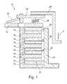
- friction clutch 10 has a designed as a clutch cover coupling part 12, which is co-rotating but axially fixed configured.
- the coupling part 12 designed as a plate carrier input part 14 is coupled, which is secured to the coupling part 12 movable in the axial direction.
- the input part 14 has a plurality of axially slidable steel plates 16, between which both sides are provided with a wear-loaded friction lining 18 friction plates 20 of a designed as a plate carrier output member 22 are arranged.
- the steel plates 16 and the friction plates 20 can be compressed by means of an actuating element 24 designed as an actuating pot.
- the actuating element 24 can act on a support piece 26 of the input part 14 in order to displace the input part 14 in the axial direction relative to the output part 22.
- the support member 26 and the coupling part 12 designed as a leaf spring return spring 28 is firmly connected.
- the friction clutch is designed as a "normally closed".
- the return spring 28 can press the input part 14 with the output part 22 frictionally in a missing actuated by the actuating element actuating force F.
- an actuating force F acting on the actuating element 24 can pull the input part 14 away from the output part 22 so that the input part 14 can vent from the output part 22 and a frictional contact between the steel plates 16 and the friction plates 20 is released.
- the input part 14 is designed to rotate limited to the coupling part 12 to allow a relative rotation of the input part 14 relative to the coupling part 12 with a change in the angle of attack of the return spring 28 over the stroke of the input part 14.
- the friction clutch 10 additionally has a compensating spring 30 designed as a plate spring, which acts on the support piece 26 of the input part 14 and the coupling part 12.
- the compensation spring 30 is thereby connected in parallel with the return spring 28.
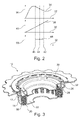
- the designed as a plate spring compensation spring 30 may have a compensating spring characteristic 34 of a compensating spring force 36 due to their design via a corresponding with the spring in the direction of the actuating force F Ausgurweg 32 of the actuating element 36, which extends degressive in a partial area, as in Fig. 2 shown.
- the return spring 28 configured as a leaf spring can have a return spring characteristic curve 38 of a restoring spring force 40 via the release travel 32 corresponding to the spring travel, which can be substantially linearly progressive.
- the Kompensationsfederkennline 34 can be degressive, while the Return spring characteristic 38 progressively or vice versa.
- the slopes of the compensation spring characteristic 34 and the return spring characteristic 38 have different signs.
- the compensation spring characteristic curve 34 extends substantially linearly in this subarea, so that it is possible to compensate for a change in the return spring force 40 by a corresponding change in the compensating spring force 36.
- a total spring characteristic 48 of a resulting force 50 resulting from the return spring force 40 and the compensating spring force 36 can thereby be achieved be substantially constant.
- the resulting force 50 acts on the coupling part 12 and the support piece 26 of the input part 14 and thus corresponds to the force acting on the friction plates 20 contact pressure, which must be overcome by the operating force F at an opening of the friction clutch 10.
- the actuation force F can overcome the substantially constant resultant force 50, without having to reserve any special power reserves, so that reliable actuation of the friction clutch 10 is made possible with little design effort and a low actuation force F.
- the friction clutch 10 may have a particularly compact structure, so that the friction clutch 10 can be used in particular for motorcycles.
- the compensation spring 30 can optionally be connected to the supporting piece 26 so that it can not rotate in a limited manner, in particular captively.
- the compensation spring 30 may preferably be pivotable about a pivotally extending in the circumferential direction pivot point by a change in its conicity via a supported on the coupling part 12 tilting ring 52.
Landscapes
- Engineering & Computer Science (AREA)
- General Engineering & Computer Science (AREA)
- Mechanical Engineering (AREA)
- Mechanical Operated Clutches (AREA)
- Braking Arrangements (AREA)
Applications Claiming Priority (1)
| Application Number | Priority Date | Filing Date | Title |
|---|---|---|---|
| DE102014200527.2A DE102014200527A1 (de) | 2014-01-14 | 2014-01-14 | Reibungskupplung |
Publications (2)
| Publication Number | Publication Date |
|---|---|
| EP2894362A2 true EP2894362A2 (fr) | 2015-07-15 |
| EP2894362A3 EP2894362A3 (fr) | 2016-05-04 |
Family
ID=52023293
Family Applications (1)
| Application Number | Title | Priority Date | Filing Date |
|---|---|---|---|
| EP14197170.5A Withdrawn EP2894362A3 (fr) | 2014-01-14 | 2014-12-10 | Embrayage à friction |
Country Status (2)
| Country | Link |
|---|---|
| EP (1) | EP2894362A3 (fr) |
| DE (1) | DE102014200527A1 (fr) |
Cited By (1)
| Publication number | Priority date | Publication date | Assignee | Title |
|---|---|---|---|---|
| WO2017097296A1 (fr) * | 2015-12-08 | 2017-06-15 | Schaeffler Technologies AG & Co. KG | Dispositif d'accouplement comportant des moyens pour générer une force de ressort, venant en appui de la pression de contact, en fonction de l'état de rotation |
Families Citing this family (2)
| Publication number | Priority date | Publication date | Assignee | Title |
|---|---|---|---|---|
| US10214101B2 (en) | 2016-04-27 | 2019-02-26 | Deere & Company | Work vehicle drive assembly |
| DE102017008624B4 (de) | 2017-09-14 | 2026-02-12 | Schaeffler Technologies AG & Co. KG | Drehmomentübertragungseinrichtung |
Citations (1)
| Publication number | Priority date | Publication date | Assignee | Title |
|---|---|---|---|---|
| DE102010048827A1 (de) | 2009-10-29 | 2011-05-05 | Schaeffler Technologies Gmbh & Co. Kg | Kupplung mit Vorkupplung und Hauptkupplung |
Family Cites Families (4)
| Publication number | Priority date | Publication date | Assignee | Title |
|---|---|---|---|---|
| DD118151A1 (fr) * | 1975-02-10 | 1976-02-12 | ||
| US6827192B2 (en) * | 2002-04-25 | 2004-12-07 | Zf Sachs Ag | Resilient plate for adjustable clutches |
| DE102011084840A1 (de) * | 2011-10-20 | 2013-04-25 | Schaeffler Technologies AG & Co. KG | Reibungskupplungseinrichtung |
| DE102011085139A1 (de) * | 2011-10-25 | 2013-04-25 | Schaeffler Technologies AG & Co. KG | Reibungskupplungseinrichtung |
-
2014
- 2014-01-14 DE DE102014200527.2A patent/DE102014200527A1/de not_active Withdrawn
- 2014-12-10 EP EP14197170.5A patent/EP2894362A3/fr not_active Withdrawn
Patent Citations (1)
| Publication number | Priority date | Publication date | Assignee | Title |
|---|---|---|---|---|
| DE102010048827A1 (de) | 2009-10-29 | 2011-05-05 | Schaeffler Technologies Gmbh & Co. Kg | Kupplung mit Vorkupplung und Hauptkupplung |
Cited By (1)
| Publication number | Priority date | Publication date | Assignee | Title |
|---|---|---|---|---|
| WO2017097296A1 (fr) * | 2015-12-08 | 2017-06-15 | Schaeffler Technologies AG & Co. KG | Dispositif d'accouplement comportant des moyens pour générer une force de ressort, venant en appui de la pression de contact, en fonction de l'état de rotation |
Also Published As
| Publication number | Publication date |
|---|---|
| DE102014200527A1 (de) | 2015-07-16 |
| EP2894362A3 (fr) | 2016-05-04 |
Similar Documents
| Publication | Publication Date | Title |
|---|---|---|
| EP3069033B1 (fr) | Embrayage à friction | |
| EP3069035B1 (fr) | Embrayage à friction | |
| EP2776727A1 (fr) | Embrayage | |
| EP3069034B1 (fr) | Système en rampe permettant l'actionnement d'un embrayage à friction | |
| EP3074653B1 (fr) | Système d'embrayage | |
| WO2015127929A1 (fr) | Dispositif d'embrayage | |
| DE102014204001A1 (de) | Blattfeder für eine Reibungskupplung sowie Verwendung einer Blattfeder | |
| EP2894362A2 (fr) | Embrayage à friction | |
| DE102013207694B4 (de) | Sensierring für eine weggesteuerte Nachstelleinrichtung einer Reibungskupplung | |
| WO2015165460A2 (fr) | Système de couvercle destiné à un embrayage à friction | |
| DE102013200552B4 (de) | Doppelkupplung mit Verschleißnachstelleinrichtungen | |
| DE102017130853B4 (de) | Kupplungseinrichtung | |
| DE102015213951A1 (de) | Lamellenpaket für eine Mehrscheibenkupplung und Verfahren zur Montage eines Lamellenpakets | |
| WO2019170189A1 (fr) | Embrayage à friction | |
| DE102009034810A1 (de) | Drehmomentübertragungseinrichtung | |
| DE102014225788A1 (de) | Selbstnachstellende Kupplung mit federzungenaufweisendem Rampenring zur Reduzierung des Drop-Offs | |
| DE102013218723A1 (de) | Deckelanordnung für eine Reibungskupplung | |
| WO2020088710A1 (fr) | Embrayage à friction | |
| DE102019218519A1 (de) | Schaltelement | |
| DE102012213658A1 (de) | Kupplungsvorrichtung | |
| DE102014218664A1 (de) | Reibungskupplung | |
| DE102013218857A1 (de) | Anpressplatte für eine Reibungskupplung | |
| DE102011101564A1 (de) | Reibungskupplung | |
| DE102016201555B4 (de) | Kupplungsvorrichtung | |
| DE102017112332A1 (de) | Mehrscheibenkupplung |
Legal Events
| Date | Code | Title | Description |
|---|---|---|---|
| PUAI | Public reference made under article 153(3) epc to a published international application that has entered the european phase |
Free format text: ORIGINAL CODE: 0009012 |
|
| 17P | Request for examination filed |
Effective date: 20141210 |
|
| AK | Designated contracting states |
Kind code of ref document: A2 Designated state(s): AL AT BE BG CH CY CZ DE DK EE ES FI FR GB GR HR HU IE IS IT LI LT LU LV MC MK MT NL NO PL PT RO RS SE SI SK SM TR |
|
| AX | Request for extension of the european patent |
Extension state: BA ME |
|
| PUAL | Search report despatched |
Free format text: ORIGINAL CODE: 0009013 |
|
| AK | Designated contracting states |
Kind code of ref document: A3 Designated state(s): AL AT BE BG CH CY CZ DE DK EE ES FI FR GB GR HR HU IE IS IT LI LT LU LV MC MK MT NL NO PL PT RO RS SE SI SK SM TR |
|
| AX | Request for extension of the european patent |
Extension state: BA ME |
|
| RIC1 | Information provided on ipc code assigned before grant |
Ipc: F16D 13/54 20060101ALI20160330BHEP Ipc: F16D 13/04 20060101AFI20160330BHEP |
|
| R17P | Request for examination filed (corrected) |
Effective date: 20161104 |
|
| RBV | Designated contracting states (corrected) |
Designated state(s): AL AT BE BG CH CY CZ DE DK EE ES FI FR GB GR HR HU IE IS IT LI LT LU LV MC MK MT NL NO PL PT RO RS SE SI SK SM TR |
|
| GRAP | Despatch of communication of intention to grant a patent |
Free format text: ORIGINAL CODE: EPIDOSNIGR1 |
|
| INTG | Intention to grant announced |
Effective date: 20190121 |
|
| STAA | Information on the status of an ep patent application or granted ep patent |
Free format text: STATUS: THE APPLICATION HAS BEEN WITHDRAWN |
|
| 18W | Application withdrawn |
Effective date: 20190301 |
|
| P01 | Opt-out of the competence of the unified patent court (upc) registered |
Effective date: 20230523 |