EP2894389B1 - Remplacement de lampes à incandescence sur des signaux ferroviaires par des diodes électroluminescentes - Google Patents
Remplacement de lampes à incandescence sur des signaux ferroviaires par des diodes électroluminescentes Download PDFInfo
- Publication number
- EP2894389B1 EP2894389B1 EP14151166.7A EP14151166A EP2894389B1 EP 2894389 B1 EP2894389 B1 EP 2894389B1 EP 14151166 A EP14151166 A EP 14151166A EP 2894389 B1 EP2894389 B1 EP 2894389B1
- Authority
- EP
- European Patent Office
- Prior art keywords
- circuit arrangement
- point
- voltage
- slave
- impedance
- Prior art date
- Legal status (The legal status is an assumption and is not a legal conclusion. Google has not performed a legal analysis and makes no representation as to the accuracy of the status listed.)
- Active
Links
- 238000000034 method Methods 0.000 claims description 16
- 230000004913 activation Effects 0.000 claims description 4
- 230000003213 activating effect Effects 0.000 claims 1
- 230000005540 biological transmission Effects 0.000 claims 1
- 238000012544 monitoring process Methods 0.000 description 13
- 238000010586 diagram Methods 0.000 description 4
- 238000012423 maintenance Methods 0.000 description 2
- 230000004907 flux Effects 0.000 description 1
- 238000011144 upstream manufacturing Methods 0.000 description 1
- 210000003462 vein Anatomy 0.000 description 1
Images



Classifications
-
- B—PERFORMING OPERATIONS; TRANSPORTING
- B61—RAILWAYS
- B61L—GUIDING RAILWAY TRAFFIC; ENSURING THE SAFETY OF RAILWAY TRAFFIC
- B61L5/00—Local operating mechanisms for points or track-mounted scotch-blocks; Visible or audible signals; Local operating mechanisms for visible or audible signals
- B61L5/12—Visible signals
- B61L5/18—Light signals; Mechanisms associated therewith, e.g. blinders
- B61L5/1809—Daylight signals
- B61L5/1881—Wiring diagrams for power supply, control or testing
-
- B—PERFORMING OPERATIONS; TRANSPORTING
- B61—RAILWAYS
- B61L—GUIDING RAILWAY TRAFFIC; ENSURING THE SAFETY OF RAILWAY TRAFFIC
- B61L2207/00—Features of light signals
- B61L2207/02—Features of light signals using light-emitting diodes [LEDs]
Definitions
- LEDs Light-emitting diodes
- the rail network is essentially finished in many countries, incandescent lamps are widely used. They should therefore be able to be replaced by light emitting diodes on systems that are in operation.
- the existing control circuit which represents a significant part of the approval of the system, should be able to be maintained. The possibility of such maintenance is called retrofit.
- the special challenge with main and presignal signals lies in the precise current monitoring of the interlocking as well as the fact that the luminous points of a driving concept are switched on as series connection. Furthermore, the safety is to pay particular attention, since a failure of a luminous point can have an immediate endangerment of a train result.
- the document WO03 / 096753 A1 discloses a circuit arrangement for operating a luminous sign, in particular an LED signal according to the preamble of claim 1.
- LED-emitting diodes as a retrofit for main signals are not yet available.
- LED-based luminous points require a special control element or a special configuration of the existing control and are currently only available for electronic signal boxes, which were designed from the start for operation with LEDs.
- the present invention is therefore based on the object, a use of light emitting diodes in train signals then too if the interlocking has been designed for the operation of railway signals with incandescent lamps.
- a circuit arrangement for a railway signal comprises several luminous points.
- the luminous dots each form a driving concept in various combinations.
- the circuit arrangement is designed for each driving concept to define exactly one of the luminous dots as a master point.
- the circuit arrangement is designed to operate the luminous point defined as a master point of a driving concept with more than one impedance.
- the circuit arrangement is configured to operate the master point with a fixed starting impedance and based on this to determine a voltage with which the driving concept is currently being operated.
- a method for operating a railway signal with light-emitting diodes is presented.
- the railway signal can be controlled by an interlocking, which is designed for a light bulb signal.
- one of the luminous points of a driving concept is defined as a master point.
- the driving concept comprises a selection of the luminous points of the railway signal.
- the driving concept is switched on by the signal box. When switching on the driving concept, each of the luminous points of the driving concept initially assumes a fixed electrical starting impedance.
- the voltage is determined above the master point. Based on the determined voltage, it is determined with which brightness value the signal box intends to operate the path signal.
- the impedance of the master point is adjusted so that the master point is operated with the brightness value intended by the interlocking.
- FIG. 1 shows a block diagram of a railway infrastructure which includes a signal box 2 and a railway signal 3 according to a preferred embodiment of the invention.
- the path signal 3 comprises a plate 4 with luminous points 11, 12, 13, 14, 15, 16.
- the path signal 3 also comprises a circuit arrangement 1 for driving the luminous points 11, 12, 13, 14, 15, 16.
- the circuit arrangement 1 comprises a Step down converter 40 and a system 50 for monitoring one, several, or all luminous points 11, 12, 13, 14, 15, 16.
- Driving terms H, F1, F2, F3, F5, F6 are selected by selecting the luminous points 11, 12, 13, 14, 15, 16 defines. The selections are also called combinations.
- FIG. 2A-2F represent different driving concepts H, F1, F2, F3, F5, F6 using the example of the L-signal system of a main signal of the Swiss Federal Railways (SBB)
- FIG. 2A shown driving term H means "stop" while in the Figures 2B-2F illustrated driving concepts F1, F2, F3, F5, F6 representing different speeds to be traveled.
- the signal box 2 is configured to switch the train signal, respectively its driving terms H, F1, F2, F3, F5, F6 with voltages as if the luminous points 11, 12, 13, 14, 15, 16 of the railway signal 3 equipped with incandescent lamps ,
- the driving terms H, F1, F2, F3, F5, F6 are switched by the interlocking 2, wherein for each driving concept H, F1, F2, F3, F5, F6 usually a separate wire to the train signal 3 is already laid while for the return line usually only one wire is used for the driving terms H, F1, F2, F3, F5, F6.
- the interlocking 2 is designed so that it can control the path signals 3 with at least two different voltages, for example, at least one day voltage and a night voltage that is lower than the day voltage to account for the different brightness ratios.
- the path signal 3 comprises the circuit arrangement 1.
- the circuit arrangement 1 is designed so that it can be operated by the offset unit configured as the interlocking 2, and the driving terms H, F1, F2, F3, F5, F6 each by a serial circuit to the driving concept H, F1, F2, F3, F5, F6 belonging luminous points 11, 12, 13, 14, 15, 16 can turn on.
- the circuit arrangement 1 is designed to operate exactly one of the luminous points 11, 12, 13, 14, 15, 16 as the master point M for each driving concept H, F1, F2, F3, F5, F6.
- the circuit arrangement 1 is configured to operate the luminous point 11, 12, 13, 14, 15, 16 thus defined as master point M with more than one impedance.
- the circuit arrangement 1 is designed to operate the master point M with a fixed starting impedance and based on this to determine a voltage with which the driving concept H, F1, F2, F3, F5, F6 is currently operated becomes.
- the circuit arrangement 1 is configured to detect, based on the determined voltage, whether the signal box 2 currently operates the driving concept H, F1, F2, F3, F5, F6 with a day voltage or a night voltage.
- the determined voltage represents a desired brightness value that would result if the interlocking were to drive a conventional incandescent lamp operated railway signal.
- the circuit arrangement 1 is designed on the basis of the determined voltage to set the impedance of the master point M such that the light-emitting diode of the master point M is operated with the desired brightness value.
- the circuit arrangement 1 is designed to operate those luminous points 11, 12, 13, 14, 15, 16 of a driving concept H, F1, F2, F3, F5, F6, which are not master point M, as slave points S.
- the circuit arrangement 1 is therefore configured to control the further luminous points 11, 12, 13, 14, 15, 16 of the driving concept H, F1, F2, F3, F5, F6 defined as slave points, by the slave point S the determined voltage and a Impedance value with which the slave point S is to be operated, is transmitted.
- the circuit arrangement 1 is designed to control the impedance of the slave point or points S of the driving concept, which light up or illuminate the slave points S equipped with a light-emitting diode with the desired brightness value.
- the circuit arrangement 1 is configured to operate the slave point S with a fixed starting impedance and based on this to enable the master point M to determine a voltage with which the driving concept H, F1, F2, F3, F5, F6 is currently being operated.
- the master point M is one, several or all driving terms covered by the circuit arrangement 1.
- the slave points S by the circuit arrangement 1 includes.
- the luminous dots 11, 12, 13, 14, 15, 16 are covered by the circuit arrangement 1.
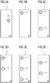
- FIGS. 3A to 3F show possible definitions of the luminous points 11, 12, 13, 14, 15, 16 of the in the FIGS. 2A to 2F Driving terms H, F1, F2, F3, F5, F6 as master points M and slave points S.
- the luminous points 11, 12, 13, 14, 15, 16 are defined as master and slave points that at each driving concept H, F1, F2, F3, F5, F6 exactly one master point M is involved.
- Zero to two slave points S are assigned to this master point M, whereby one slave point may be assigned to several master points.
- the circuit arrangement 1 is designed to operate each of the luminous points 11, 12, 13, 14, 15, 16 of the driving concept H, F1, F2, F3, F5, F6 with the fixed starting impedance, and to switch on each of the slave points S. to register the driving concept and report this to the master point M.
- the fixed starting impedance preferably coincides with an operating point of an incandescent lamp. This has the advantage that the present in the existing interlocking 2, set on the incandescent lamps used, control and monitoring circuit can be used.
- FIG. 4 7 shows a known buck converter 40.
- the buck converter 40 is used for realizing a variable load at the master point M, the slave point S, or generally at one, several or all of the luminous points 11, 12, 13, 14, 15, 16 used.
- a variable load means a variable impedance.
- the impedance can be selected within certain limits, since the duty cycle for the transistor T can not be resolved arbitrarily exactly.
- the buck converter 40 comprises, for example, a switching element T1, an inductance L1 and a fixed load R L.
- the switching element T1 is, for example, a transistor T1, which comprises a connection for a control circuit S.
- T1 conducts: the current flows from the source DC via T1, L1 and RL.
- L1 stores energy.
- the source "sees” the impedance R L.
- T1 blocks: the current flows through D1, L1 and RL.
- L1 gives off energy.
- the ON / OFF time ratio is selected at T1
- the time average of the current taken from the DC source changes.
- the mean value of the load which the source DC "sees” also changes.
- the buck converter 40 was originally designed for DC voltage, but can also be a variable load to AC voltage, for example, by a bridge rectifier is connected upstream.
- a further exemplary embodiment relates to a method for operating the path signal 3 with light-emitting diodes.
- the railway signal 3 can be controlled by a signal box 2.
- the signal box 3 is designed for a light bulb signal.
- a driving concept H, F1, F2, F3, F5, F6 of the path signal 3 comprises a selection of luminous points 11, 12, 13, 14, 15, 16 of the path signal.
- one of the luminous points 11, 12, 13, 14, 15, 16 of one of the driving terms H, F1, F2, F3, F5, F6 is defined as master point M.
- the driving concept H, F1, F2, F3, F5, F6 is turned on by the interlocking 2.
- each of the luminous points 11, 12, 13, 14, 15, 16 of the driving concept H F1, F2, F3, F5, F6 first assumes a fixed electrical starting impedance. Thereafter, the voltage across the master point M is determined. Based on the determined voltage, it is determined with which brightness value the interlocking 2 the Railway signal intended to operate 3. For example, it is determined whether the signal box 2 currently operates the path signal 3 with a day voltage or a night voltage, which is designed for a conventional bulb path signal. The impedance of the master point M is adjusted, so that a light-emitting diode of the master point M is operated with the intention by the interlocking 2 brightness value.
- the other luminous points 11, 12, 13, 14, 15, 16 of the driving concept H, F1, F2, F3, F5, F6 are defined as slave points S.
- the slave points S signal their connection to the master point M.
- the master point M transmits the brightness value to the slave points S.
- the impedance of the equipped with a LED slave points is adjusted so that they are operated with the intended by the interlocking 2 brightness value.
- a master point M is defined for each driving concept H, F1, F2, F3, F5, F6 of the railway signal.
- Each of these master points M can be assigned zero to two slave points S per driving concept.
- the problem of enabling the use of LEDs in train signals even when the interlocking has been designed for the operation of railway signals with incandescent lamps solved by a special master / slave architecture and a method for load distribution. Since in the installed base signal systems "series driving concept circuit" occur for the vein saving, a load distribution logic (load balancing) is required.
- the luminous points are defined as master points M and slave points S, so that exactly one master point M is involved in each driving concept.
- Zero to two slave points S are assigned to this master point, whereby one slave point S may be assigned to several master points.
- the fixed starting impedance must match an operating point of the incandescent lamp in order to adjust the operating conditions for which the system was designed.
- each light spot can monitor itself. If he detects an error, he interrupts the current flow high impedance, which leads to the shutdown of all involved light points. This fault is detected by the interlocking, and automatically "stop" turned on.
- FIG. 5 shows a system 50 that monitors a master point M, a slave point S, or any of the ones in FIG FIG. 1 illustrated luminous points 11, 12, 13, 14, 15, 16 allows. It is an example of monitoring the luminous flux with superposition.
- the system 50 includes a monitoring circuit 54, 55, a in one of the luminous points 11, 12, 13, 14, 15, 16 arranged light-emitting diode 51, a photocell 53, and a signal optics 56th
- the monitoring of a luminous point 11, 12, 13, 14, 15, 16 takes place in a command / message procedure.
- a portion 52 of the light is coupled to a photodiode 53.
- a first monitoring circuit 54 determines whether the luminous spot generates sufficient light and, if appropriate, triggers the switching off of the path signal 3 with the aid of the monitoring circuit 55. By superposing the light of the light-emitting diode 51 with a high-frequency signal, the generated light can be distinguished from the ambient light.
- a method for monitoring a luminous spot 11, 12, 13, 14, 15, 16 operated by means of a light-emitting diode 51 is preceded by a path signal 3.
- light is generated by means of the light-emitting diode 51 by means of a significant drive signal.
- a portion of the light generated by the light-emitting diode 51 is coupled out of the path signal 3 by the signal optics 56 as part of a driving concept H, F1, F2, F3, F5, F6.
- a smaller portion 52 of the light generated by the light emitting diode 51 is coupled to the photodiode 53.
- An electrical output signal generated thereby by the photodiode 53 is input to the monitoring circuit 54.
- the monitoring circuit 54 analyzes the output signal and determines whether the light emitting diode 51 generates enough light.
- the drive signal is sufficiently significant that the portion of the light of the light emitting diode 51 produced by the drive signal is distinguishable in the output signal from the portion of the output signal generated by ambient light.
- the monitoring circuit 54 may isolate the portion of the output signal generated by the light emitting diode 51 from the portion of the output signal generated by ambient light. A sufficient significance of the drive signal can be ensured, for example, by means of a frequency of the drive signal. If by the monitoring circuit 54 it is determined that the luminous point 11, 12, 13, 14, 15, 16 does not generate enough light, the path signal 3 is turned off.
Landscapes
- Engineering & Computer Science (AREA)
- Mechanical Engineering (AREA)
- Train Traffic Observation, Control, And Security (AREA)
Claims (11)
- Montage de circuit (1) pour un signal ferroviaire (3) comprenant plusieurs points lumineux DEL (11, 12, 13, 14, 15, 16) qui, en différentes combinaisons, forment chacun une image (H, F1, F2, F3, F5, F6), ce montage de circuit (1) étant réalisé de sorte que:a) ce montage de circuit fonctionne par un poste d'aiguillage (2) configuré comme une unité décalée et les images (H, F1, F2, F3, F5, F6) sont chacune branchées par le circuit en série des points lumineux DEL (11, 12, 13, 14, 15, 16) relatifs à l'image (H, F1, F2, F3, F5, F6),b) ce montage de circuit pour chaque image (H, F1, F2, F3, F5, F6) fait fonctionner précisément l'un des points lumineux DEL (11, 12, 13, 14, 15, 16) prévu pour cette image-là comme point-maître (M) avec une impédance réglable;c) ce montage de circuit fait fonctionner le point-maître (M) avec une impédance initiale fixe et, sur cette base, détermine une tension à laquelle l'image (H, F1, F2, F3, F5, F6) doit fonctionner de manière prédéfinie à l'instant même du poste d'aiguillage (2), ce montage de circuit réglant l'impédance du point-maître (M) à l'aide de cette tension déterminée de sorte que le point lumineux DEL du point-maître (M) peut fonctionner avec une valeur de luminosité correspondant à la tension déterminée; etd) au moins un autre point lumineux DEL (11, 12, 13, 14, 15, 16) fonctionnant avec une impédance initiale prédéfinie de l'image, peut être commandé comme point asservi (S) par le montage de circuit de sorte que ce montage de circuit transmet au point asservi (S) la tension déterminée ainsi qu'une valeur d'impédance censée faire fonctionner le point asservi (S).
- Montage de circuit (1) selon la revendication 1, la détermination de la tension, comprenant la détermination, si l'image (H, F1, F2, F3, F5, F6) doit fonctionner à l'instant avec une tension de jour ou une tension de nuit.
- Montage de circuit (1) selon l'une des revendications précédentes, chacun des points lumineux DEL (11, 12, 13, 14, 15, 16) d'une image (H, F1, F2, F3, F5, F6) pouvant fonctionner avec l'impédance initiale fixe, et le branchement de chacun des points asservis (S) sur le point-maître (M) peut être signalé.
- Montage de circuit (1) selon l'une des revendications précédentes, l'impédance initiale fixe s'accordant avec le point de fonctionnement d'une lampe à incandescence.
- Montage de circuit (1) selon l'une des revendications précédentes, à chaque point-maître (M) étant associés de zéro à deux points asservis (S).
- Montage de circuit (1) selon l'une des revendications précédentes, ce montage de circuit (1) comprenant une logique de distribution de charge.
- Signal ferroviaire (3) comprenant un montage de circuit (1) et des points lumineux DEL (11, 12, 13, 14, 15, 16) selon l'une des revendications précédentes.
- Procédé de fonctionnement d'un signal ferroviaire (3) avec des points lumineux DEL, ce signal ferroviaire (3) étant enclenché par un point d'aiguillage (2), lequel est prévu pour un signal ferroviaire de lampe à incandescence, une image (H, F1, F2, F3, F5, F6) du signal ferroviaire (3) comprenant une sélection de points lumineux (11, 12, 13, 14, 15, 16) connectés en série du signal ferroviaire, comprenant les étapes de procédé suivantes:- définition d'un des points lumineux DEL (11, 12, 13, 14, 15, 16) de l'image (H, F1, F2, F3, F5, F6) comme point-maître (M);- branchement de l'image (H, F1, F2, F3, F5, F6) par le poste d'aiguillage (2), lors du branchement de l'image (H, F1, F2, F3, F5, F6), chacun des points lumineux DEL (11, 12, 13, 14, 15, 16) de l'image (H, F1, F2, F3, F5, F6) adoptant d'abord une impédance initiale électrique fixe;- détermination de la tension par le point-maître (M) et détermination à l'aide de la tension déterminée, de la valeur de luminosité à laquelle le poste d'aiguillage envisage de faire fonctionner le signal ferroviaire;- adaptation de l'impédance du point-maître (M), de sorte que le point-maître (M) fonctionne avec la valeur de luminosité envisagée par le poste d'aiguillage (2); et- définition du ou des autres points lumineux DEL (11, 12, 13, 14, 15, 16) de l'image (H, F1, F2, F3, F5, F6) comme points asservis (S);- demande de branchement du ou des points asservis (S) au point-maître (M) ;- transmission de la valeur de luminosité par le point-maître (M) au ou aux points asservis (S);- adaptation de l'impédance du ou des points asservis (S) de sorte que le ou les points asservis (S) fonctionne/nt avec la valeur de luminosité envisagée par le poste d'aiguillage (2).
- Procédé selon la revendication 8, la détermination de la tension par le point-maître (M), comprenant la détermination si le poste d'aiguillage (2) fait fonctionner le signal ferroviaire (3) à l'instant avec une tension de jour ou une tension de nuit.
- Procédé selon les revendications 8 ou 9, l'impédance initiale fixe s'accordant avec le point de fonctionnement d'une lampe à incandescence.
- Procédé selon l'une des revendications 8 à 10, pour chaque image (H, F1, F2, F3, F5, F6) du signal ferroviaire, un point-maître (M) étant fixé, auquel une sélection de zéro à deux points asservis (S) est associée.
Priority Applications (1)
| Application Number | Priority Date | Filing Date | Title |
|---|---|---|---|
| EP14151166.7A EP2894389B1 (fr) | 2014-01-14 | 2014-01-14 | Remplacement de lampes à incandescence sur des signaux ferroviaires par des diodes électroluminescentes |
Applications Claiming Priority (1)
| Application Number | Priority Date | Filing Date | Title |
|---|---|---|---|
| EP14151166.7A EP2894389B1 (fr) | 2014-01-14 | 2014-01-14 | Remplacement de lampes à incandescence sur des signaux ferroviaires par des diodes électroluminescentes |
Publications (2)
| Publication Number | Publication Date |
|---|---|
| EP2894389A1 EP2894389A1 (fr) | 2015-07-15 |
| EP2894389B1 true EP2894389B1 (fr) | 2019-10-23 |
Family
ID=49989533
Family Applications (1)
| Application Number | Title | Priority Date | Filing Date |
|---|---|---|---|
| EP14151166.7A Active EP2894389B1 (fr) | 2014-01-14 | 2014-01-14 | Remplacement de lampes à incandescence sur des signaux ferroviaires par des diodes électroluminescentes |
Country Status (1)
| Country | Link |
|---|---|
| EP (1) | EP2894389B1 (fr) |
Family Cites Families (3)
| Publication number | Priority date | Publication date | Assignee | Title |
|---|---|---|---|---|
| DE59406833D1 (de) * | 1993-11-05 | 1998-10-08 | Siemens Schweiz Ag | Schaltungsanordnung für eisenbahn-lichtsignalanlagen |
| DE10221573B4 (de) * | 2002-05-08 | 2004-03-18 | Siemens Ag | Schaltungsanordnung zum Betreiben eines Leuchtzeichens |
| EP2463174B1 (fr) * | 2010-12-09 | 2013-10-30 | Siemens Schweiz AG | Dispositif et procédé pour remplacer une lampe à incandescence d'un signal lumineux |
-
2014
- 2014-01-14 EP EP14151166.7A patent/EP2894389B1/fr active Active
Non-Patent Citations (1)
| Title |
|---|
| None * |
Also Published As
| Publication number | Publication date |
|---|---|
| EP2894389A1 (fr) | 2015-07-15 |
Similar Documents
| Publication | Publication Date | Title |
|---|---|---|
| WO2001091521A1 (fr) | Installation de signalisation routiere avec source lumineuse a diode electroluminescente | |
| DE102004002026A1 (de) | Ansteuerung von Leuchtmittel-Betriebsgeräten über einen modulierten DC-Bus | |
| EP1992542B2 (fr) | Agencement DEL pour émetteurs de signaux lumineux pour passages à niveaux, émetteur de signaux lumineux pour passages à niveaux dotés d'un tel dispositif DEL et procédé de fonctionnement d'un dispositif DEL | |
| DE202008002883U1 (de) | Schaltung zur Ansteuerung mindestens einer Leuchteinheit und Leuchte | |
| DE102015211454A1 (de) | Sensorspeisung mit einem Konstantstrom-Konverter für Leuchtmittel | |
| DE102010030520A1 (de) | Arbeitsleuchte für ein Nutzfahrzeug, insbesondere Flurförderzeug | |
| EP2687418B1 (fr) | Signal de trajectoire à LED pour le transport ferroviaire et interface pour un tel signal de trajectoire à LED | |
| EP2894389B1 (fr) | Remplacement de lampes à incandescence sur des signaux ferroviaires par des diodes électroluminescentes | |
| DE102008029725A1 (de) | Signalgeber | |
| EP2182778B1 (fr) | Procédé de commande d'une lampe extérieure et lampe correspondante | |
| EP2866524A2 (fr) | Système et procédé de surveillance de plusieurs rampes de DEL et éclairage à DEL doté d'un tel système | |
| DE112011100717B4 (de) | Betriebsgerät für Leuchtmittel sowie Bussystem und Verfahren zum Betreiben eines Betriebsgerätes | |
| EP3235349B1 (fr) | Régulation de luminosité d'une installation de signaux lumineux | |
| DE10206649A1 (de) | Anzeigevorrichtung | |
| DE10358993B4 (de) | Lichtsignalgeber und Lichtsignalanlage mit einem Lichtsignalgeber | |
| EP3934384B1 (fr) | Agencement destiné à la commande de del | |
| DE102013108689B3 (de) | Schaltung zur Regelung der Leistungsaufnahme einer LED-Einheit sowie LED-Leuchte mit einer solchen LED-Einheit | |
| EP2564488A2 (fr) | Unité d'alimentation en énergie pour moyens lumineux de signal avec sources d`energie avec des masses separees | |
| DE202010016339U1 (de) | Schaltungsanordnung | |
| DE102011001549A1 (de) | Anordnung und Verfahren zum Steuern und Überwachen der Außenbeleuchtung von Schienenfahrzeugen | |
| DE202008006297U1 (de) | LED Anordnung für Lichtsignalgeber insbesondere für Bahnübergänge sowie Lichtsignalgeber insbesondere für Bahnübergänge mit einer solchen LED-Anordnung | |
| EP1741613A1 (fr) | Interface entre un poste d'aiguillage et un signal avec des diodes électroluminescentes | |
| DE102012019861B4 (de) | Verfahren zurn Betreiben eines Signalgebers und Signalgeber | |
| DE102010048285B4 (de) | Beleuchtungsanordnung im untertägigen Bergbau und Verfahren zur Regelung einer Untertagebeleuchtung | |
| EP2691266B1 (fr) | Module lumineux pour véhicule sur rails |
Legal Events
| Date | Code | Title | Description |
|---|---|---|---|
| PUAI | Public reference made under article 153(3) epc to a published international application that has entered the european phase |
Free format text: ORIGINAL CODE: 0009012 |
|
| 17P | Request for examination filed |
Effective date: 20140114 |
|
| AK | Designated contracting states |
Kind code of ref document: A1 Designated state(s): AL AT BE BG CH CY CZ DE DK EE ES FI FR GB GR HR HU IE IS IT LI LT LU LV MC MK MT NL NO PL PT RO RS SE SI SK SM TR |
|
| AX | Request for extension of the european patent |
Extension state: BA ME |
|
| R17P | Request for examination filed (corrected) |
Effective date: 20160107 |
|
| RBV | Designated contracting states (corrected) |
Designated state(s): AL AT BE BG CH CY CZ DE DK EE ES FI FR GB GR HR HU IE IS IT LI LT LU LV MC MK MT NL NO PL PT RO RS SE SI SK SM TR |
|
| STAA | Information on the status of an ep patent application or granted ep patent |
Free format text: STATUS: EXAMINATION IS IN PROGRESS |
|
| 17Q | First examination report despatched |
Effective date: 20180327 |
|
| RAP1 | Party data changed (applicant data changed or rights of an application transferred) |
Owner name: SIEMENS MOBILITY AG |
|
| GRAP | Despatch of communication of intention to grant a patent |
Free format text: ORIGINAL CODE: EPIDOSNIGR1 |
|
| STAA | Information on the status of an ep patent application or granted ep patent |
Free format text: STATUS: GRANT OF PATENT IS INTENDED |
|
| INTG | Intention to grant announced |
Effective date: 20190716 |
|
| GRAS | Grant fee paid |
Free format text: ORIGINAL CODE: EPIDOSNIGR3 |
|
| GRAA | (expected) grant |
Free format text: ORIGINAL CODE: 0009210 |
|
| STAA | Information on the status of an ep patent application or granted ep patent |
Free format text: STATUS: THE PATENT HAS BEEN GRANTED |
|
| AK | Designated contracting states |
Kind code of ref document: B1 Designated state(s): AL AT BE BG CH CY CZ DE DK EE ES FI FR GB GR HR HU IE IS IT LI LT LU LV MC MK MT NL NO PL PT RO RS SE SI SK SM TR |
|
| REG | Reference to a national code |
Ref country code: GB Ref legal event code: FG4D Free format text: NOT ENGLISH |
|
| REG | Reference to a national code |
Ref country code: CH Ref legal event code: EP Ref country code: CH Ref legal event code: NV Representative=s name: SIEMENS SCHWEIZ AG, CH |
|
| REG | Reference to a national code |
Ref country code: IE Ref legal event code: FG4D Free format text: LANGUAGE OF EP DOCUMENT: GERMAN |
|
| REG | Reference to a national code |
Ref country code: DE Ref legal event code: R096 Ref document number: 502014012889 Country of ref document: DE |
|
| REG | Reference to a national code |
Ref country code: AT Ref legal event code: REF Ref document number: 1194044 Country of ref document: AT Kind code of ref document: T Effective date: 20191115 |
|
| REG | Reference to a national code |
Ref country code: NL Ref legal event code: MP Effective date: 20191023 |
|
| REG | Reference to a national code |
Ref country code: LT Ref legal event code: MG4D |
|
| PG25 | Lapsed in a contracting state [announced via postgrant information from national office to epo] |
Ref country code: ES Free format text: LAPSE BECAUSE OF FAILURE TO SUBMIT A TRANSLATION OF THE DESCRIPTION OR TO PAY THE FEE WITHIN THE PRESCRIBED TIME-LIMIT Effective date: 20191023 Ref country code: SE Free format text: LAPSE BECAUSE OF FAILURE TO SUBMIT A TRANSLATION OF THE DESCRIPTION OR TO PAY THE FEE WITHIN THE PRESCRIBED TIME-LIMIT Effective date: 20191023 Ref country code: LV Free format text: LAPSE BECAUSE OF FAILURE TO SUBMIT A TRANSLATION OF THE DESCRIPTION OR TO PAY THE FEE WITHIN THE PRESCRIBED TIME-LIMIT Effective date: 20191023 Ref country code: PT Free format text: LAPSE BECAUSE OF FAILURE TO SUBMIT A TRANSLATION OF THE DESCRIPTION OR TO PAY THE FEE WITHIN THE PRESCRIBED TIME-LIMIT Effective date: 20200224 Ref country code: FI Free format text: LAPSE BECAUSE OF FAILURE TO SUBMIT A TRANSLATION OF THE DESCRIPTION OR TO PAY THE FEE WITHIN THE PRESCRIBED TIME-LIMIT Effective date: 20191023 Ref country code: BG Free format text: LAPSE BECAUSE OF FAILURE TO SUBMIT A TRANSLATION OF THE DESCRIPTION OR TO PAY THE FEE WITHIN THE PRESCRIBED TIME-LIMIT Effective date: 20200123 Ref country code: PL Free format text: LAPSE BECAUSE OF FAILURE TO SUBMIT A TRANSLATION OF THE DESCRIPTION OR TO PAY THE FEE WITHIN THE PRESCRIBED TIME-LIMIT Effective date: 20191023 Ref country code: GR Free format text: LAPSE BECAUSE OF FAILURE TO SUBMIT A TRANSLATION OF THE DESCRIPTION OR TO PAY THE FEE WITHIN THE PRESCRIBED TIME-LIMIT Effective date: 20200124 Ref country code: NO Free format text: LAPSE BECAUSE OF FAILURE TO SUBMIT A TRANSLATION OF THE DESCRIPTION OR TO PAY THE FEE WITHIN THE PRESCRIBED TIME-LIMIT Effective date: 20200123 Ref country code: NL Free format text: LAPSE BECAUSE OF FAILURE TO SUBMIT A TRANSLATION OF THE DESCRIPTION OR TO PAY THE FEE WITHIN THE PRESCRIBED TIME-LIMIT Effective date: 20191023 Ref country code: LT Free format text: LAPSE BECAUSE OF FAILURE TO SUBMIT A TRANSLATION OF THE DESCRIPTION OR TO PAY THE FEE WITHIN THE PRESCRIBED TIME-LIMIT Effective date: 20191023 |
|
| PG25 | Lapsed in a contracting state [announced via postgrant information from national office to epo] |
Ref country code: HR Free format text: LAPSE BECAUSE OF FAILURE TO SUBMIT A TRANSLATION OF THE DESCRIPTION OR TO PAY THE FEE WITHIN THE PRESCRIBED TIME-LIMIT Effective date: 20191023 Ref country code: RS Free format text: LAPSE BECAUSE OF FAILURE TO SUBMIT A TRANSLATION OF THE DESCRIPTION OR TO PAY THE FEE WITHIN THE PRESCRIBED TIME-LIMIT Effective date: 20191023 Ref country code: IS Free format text: LAPSE BECAUSE OF FAILURE TO SUBMIT A TRANSLATION OF THE DESCRIPTION OR TO PAY THE FEE WITHIN THE PRESCRIBED TIME-LIMIT Effective date: 20200224 |
|
| PG25 | Lapsed in a contracting state [announced via postgrant information from national office to epo] |
Ref country code: AL Free format text: LAPSE BECAUSE OF FAILURE TO SUBMIT A TRANSLATION OF THE DESCRIPTION OR TO PAY THE FEE WITHIN THE PRESCRIBED TIME-LIMIT Effective date: 20191023 |
|
| REG | Reference to a national code |
Ref country code: DE Ref legal event code: R097 Ref document number: 502014012889 Country of ref document: DE |
|
| PG2D | Information on lapse in contracting state deleted |
Ref country code: IS |
|
| PG25 | Lapsed in a contracting state [announced via postgrant information from national office to epo] |
Ref country code: CZ Free format text: LAPSE BECAUSE OF FAILURE TO SUBMIT A TRANSLATION OF THE DESCRIPTION OR TO PAY THE FEE WITHIN THE PRESCRIBED TIME-LIMIT Effective date: 20191023 Ref country code: EE Free format text: LAPSE BECAUSE OF FAILURE TO SUBMIT A TRANSLATION OF THE DESCRIPTION OR TO PAY THE FEE WITHIN THE PRESCRIBED TIME-LIMIT Effective date: 20191023 Ref country code: RO Free format text: LAPSE BECAUSE OF FAILURE TO SUBMIT A TRANSLATION OF THE DESCRIPTION OR TO PAY THE FEE WITHIN THE PRESCRIBED TIME-LIMIT Effective date: 20191023 Ref country code: DK Free format text: LAPSE BECAUSE OF FAILURE TO SUBMIT A TRANSLATION OF THE DESCRIPTION OR TO PAY THE FEE WITHIN THE PRESCRIBED TIME-LIMIT Effective date: 20191023 Ref country code: IS Free format text: LAPSE BECAUSE OF FAILURE TO SUBMIT A TRANSLATION OF THE DESCRIPTION OR TO PAY THE FEE WITHIN THE PRESCRIBED TIME-LIMIT Effective date: 20200223 |
|
| PLBE | No opposition filed within time limit |
Free format text: ORIGINAL CODE: 0009261 |
|
| STAA | Information on the status of an ep patent application or granted ep patent |
Free format text: STATUS: NO OPPOSITION FILED WITHIN TIME LIMIT |
|
| PG25 | Lapsed in a contracting state [announced via postgrant information from national office to epo] |
Ref country code: SM Free format text: LAPSE BECAUSE OF FAILURE TO SUBMIT A TRANSLATION OF THE DESCRIPTION OR TO PAY THE FEE WITHIN THE PRESCRIBED TIME-LIMIT Effective date: 20191023 Ref country code: IT Free format text: LAPSE BECAUSE OF FAILURE TO SUBMIT A TRANSLATION OF THE DESCRIPTION OR TO PAY THE FEE WITHIN THE PRESCRIBED TIME-LIMIT Effective date: 20191023 Ref country code: MC Free format text: LAPSE BECAUSE OF FAILURE TO SUBMIT A TRANSLATION OF THE DESCRIPTION OR TO PAY THE FEE WITHIN THE PRESCRIBED TIME-LIMIT Effective date: 20191023 Ref country code: SK Free format text: LAPSE BECAUSE OF FAILURE TO SUBMIT A TRANSLATION OF THE DESCRIPTION OR TO PAY THE FEE WITHIN THE PRESCRIBED TIME-LIMIT Effective date: 20191023 |
|
| GBPC | Gb: european patent ceased through non-payment of renewal fee |
Effective date: 20200123 |
|
| 26N | No opposition filed |
Effective date: 20200724 |
|
| REG | Reference to a national code |
Ref country code: BE Ref legal event code: MM Effective date: 20200131 |
|
| PG25 | Lapsed in a contracting state [announced via postgrant information from national office to epo] |
Ref country code: GB Free format text: LAPSE BECAUSE OF NON-PAYMENT OF DUE FEES Effective date: 20200123 Ref country code: LU Free format text: LAPSE BECAUSE OF NON-PAYMENT OF DUE FEES Effective date: 20200114 Ref country code: FR Free format text: LAPSE BECAUSE OF NON-PAYMENT OF DUE FEES Effective date: 20200131 |
|
| PG25 | Lapsed in a contracting state [announced via postgrant information from national office to epo] |
Ref country code: SI Free format text: LAPSE BECAUSE OF FAILURE TO SUBMIT A TRANSLATION OF THE DESCRIPTION OR TO PAY THE FEE WITHIN THE PRESCRIBED TIME-LIMIT Effective date: 20191023 Ref country code: BE Free format text: LAPSE BECAUSE OF NON-PAYMENT OF DUE FEES Effective date: 20200131 |
|
| PG25 | Lapsed in a contracting state [announced via postgrant information from national office to epo] |
Ref country code: IE Free format text: LAPSE BECAUSE OF NON-PAYMENT OF DUE FEES Effective date: 20200114 |
|
| PGFP | Annual fee paid to national office [announced via postgrant information from national office to epo] |
Ref country code: DE Payment date: 20220318 Year of fee payment: 9 |
|
| PG25 | Lapsed in a contracting state [announced via postgrant information from national office to epo] |
Ref country code: TR Free format text: LAPSE BECAUSE OF FAILURE TO SUBMIT A TRANSLATION OF THE DESCRIPTION OR TO PAY THE FEE WITHIN THE PRESCRIBED TIME-LIMIT Effective date: 20191023 Ref country code: MT Free format text: LAPSE BECAUSE OF FAILURE TO SUBMIT A TRANSLATION OF THE DESCRIPTION OR TO PAY THE FEE WITHIN THE PRESCRIBED TIME-LIMIT Effective date: 20191023 Ref country code: CY Free format text: LAPSE BECAUSE OF FAILURE TO SUBMIT A TRANSLATION OF THE DESCRIPTION OR TO PAY THE FEE WITHIN THE PRESCRIBED TIME-LIMIT Effective date: 20191023 |
|
| PG25 | Lapsed in a contracting state [announced via postgrant information from national office to epo] |
Ref country code: MK Free format text: LAPSE BECAUSE OF FAILURE TO SUBMIT A TRANSLATION OF THE DESCRIPTION OR TO PAY THE FEE WITHIN THE PRESCRIBED TIME-LIMIT Effective date: 20191023 |
|
| PGFP | Annual fee paid to national office [announced via postgrant information from national office to epo] |
Ref country code: CH Payment date: 20220411 Year of fee payment: 9 |
|
| PGFP | Annual fee paid to national office [announced via postgrant information from national office to epo] |
Ref country code: AT Payment date: 20221209 Year of fee payment: 10 |
|
| REG | Reference to a national code |
Ref country code: DE Ref legal event code: R119 Ref document number: 502014012889 Country of ref document: DE |
|
| REG | Reference to a national code |
Ref country code: CH Ref legal event code: PL |
|
| PG25 | Lapsed in a contracting state [announced via postgrant information from national office to epo] |
Ref country code: LI Free format text: LAPSE BECAUSE OF NON-PAYMENT OF DUE FEES Effective date: 20230131 Ref country code: DE Free format text: LAPSE BECAUSE OF NON-PAYMENT OF DUE FEES Effective date: 20230801 Ref country code: CH Free format text: LAPSE BECAUSE OF NON-PAYMENT OF DUE FEES Effective date: 20230131 |
|
| REG | Reference to a national code |
Ref country code: AT Ref legal event code: MM01 Ref document number: 1194044 Country of ref document: AT Kind code of ref document: T Effective date: 20240114 |
|
| PG25 | Lapsed in a contracting state [announced via postgrant information from national office to epo] |
Ref country code: AT Free format text: LAPSE BECAUSE OF NON-PAYMENT OF DUE FEES Effective date: 20240114 |
|
| PG25 | Lapsed in a contracting state [announced via postgrant information from national office to epo] |
Ref country code: AT Free format text: LAPSE BECAUSE OF NON-PAYMENT OF DUE FEES Effective date: 20240114 |