EP2894408B1 - Procédé de régulation de la température de pièces d'un bâtiment - Google Patents
Procédé de régulation de la température de pièces d'un bâtiment Download PDFInfo
- Publication number
- EP2894408B1 EP2894408B1 EP14151038.8A EP14151038A EP2894408B1 EP 2894408 B1 EP2894408 B1 EP 2894408B1 EP 14151038 A EP14151038 A EP 14151038A EP 2894408 B1 EP2894408 B1 EP 2894408B1
- Authority
- EP
- European Patent Office
- Prior art keywords
- heating
- building
- rooms
- motors
- controller
- Prior art date
- Legal status (The legal status is an assumption and is not a legal conclusion. Google has not performed a legal analysis and makes no representation as to the accuracy of the status listed.)
- Active
Links
Images
Classifications
-
- F—MECHANICAL ENGINEERING; LIGHTING; HEATING; WEAPONS; BLASTING
- F24—HEATING; RANGES; VENTILATING
- F24D—DOMESTIC- OR SPACE-HEATING SYSTEMS, e.g. CENTRAL HEATING SYSTEMS; DOMESTIC HOT-WATER SUPPLY SYSTEMS; ELEMENTS OR COMPONENTS THEREFOR
- F24D19/00—Details
- F24D19/10—Arrangement or mounting of control or safety devices
- F24D19/1006—Arrangement or mounting of control or safety devices for water heating systems
- F24D19/1009—Arrangement or mounting of control or safety devices for water heating systems for central heating
- F24D19/1015—Arrangement or mounting of control or safety devices for water heating systems for central heating using a valve or valves
-
- G—PHYSICS
- G05—CONTROLLING; REGULATING
- G05D—SYSTEMS FOR CONTROLLING OR REGULATING NON-ELECTRIC VARIABLES
- G05D23/00—Control of temperature
- G05D23/19—Control of temperature characterised by the use of electric means
- G05D23/1927—Control of temperature characterised by the use of electric means using a plurality of sensors
- G05D23/193—Control of temperature characterised by the use of electric means using a plurality of sensors sensing the temperaure in different places in thermal relationship with one or more spaces
- G05D23/1932—Control of temperature characterised by the use of electric means using a plurality of sensors sensing the temperaure in different places in thermal relationship with one or more spaces to control the temperature of a plurality of spaces
- G05D23/1934—Control of temperature characterised by the use of electric means using a plurality of sensors sensing the temperaure in different places in thermal relationship with one or more spaces to control the temperature of a plurality of spaces each space being provided with one sensor acting on one or more control means
-
- Y—GENERAL TAGGING OF NEW TECHNOLOGICAL DEVELOPMENTS; GENERAL TAGGING OF CROSS-SECTIONAL TECHNOLOGIES SPANNING OVER SEVERAL SECTIONS OF THE IPC; TECHNICAL SUBJECTS COVERED BY FORMER USPC CROSS-REFERENCE ART COLLECTIONS [XRACs] AND DIGESTS
- Y02—TECHNOLOGIES OR APPLICATIONS FOR MITIGATION OR ADAPTATION AGAINST CLIMATE CHANGE
- Y02B—CLIMATE CHANGE MITIGATION TECHNOLOGIES RELATED TO BUILDINGS, e.g. HOUSING, HOUSE APPLIANCES OR RELATED END-USER APPLICATIONS
- Y02B30/00—Energy efficient heating, ventilation or air conditioning [HVAC]
- Y02B30/70—Efficient control or regulation technologies, e.g. for control of refrigerant flow, motor or heating
Definitions
- the invention relates to a method for tempering rooms of a building according to the preamble of patent claim 1.
- Such a method is for example from the EP 2 530 390 A1 out.
- the temperature in the rooms of buildings of all kinds is regulated in modern technology.
- the rooms are heated or cooled depending on the outside temperature.
- a heating medium such as warm water
- a cooling medium such as chilled water
- the word "heating circuit” therefore applies both to the supply of a heat carrier and a cooling medium.
- the method according to the invention for the heating of rooms will be described, also representative of a cooling, which is carried out in the same way as the heating except for the medium to be transported.
- thermostats are arranged, where a set temperature can be set.
- a signal to an installed in a Schunikverteiler arrangement by which the heat supply to the corresponding room is increased or reduced until the set temperature is reached again.
- a controller and valves are arranged, one of which is installed in the inlet for the heating medium of a heating circuit. The valves are opened and closed by actuators connected to them as a function of the signals of the thermostats of the individual rooms.
- the signals can be transmitted to the controller wired or via radio.
- a building heating system with at least two, a heating fluid comprehensive heating circuits, in which in a flow pipe for the heating fluid or in a return pipe for the same an actuator for adjusting the operation of the associated heating circuit is present.
- a distributor three actuators are provided which have an electric or electrothermal actuator.
- Actuators are used to actuate the valves, which have a temperature-dependent expansion body to which an electrical heating element, such as an electrical resistance, is mounted.
- EP 2 530 390 A1 there is a method of heating a plurality of rooms of a building using a heating system with a heat source and at least one heat exchanger for each room controlled by a control valve.
- the control valves may have an electric motor equipped actuator.
- the actuators regulate the "open" state of the control valves as a function of the heat demand, the control valves are controlled by the actuators in a time-shared manner. At least one control valve is controlled so that it is open when there is no heat demand.
- the invention has for its object to make the initially described method so that it allows for reduced energy consumption a quick response to temperature changes in the rooms of the building.
- an electric motor actuated actuators are for example in the DE 10 2010 024 280 A1 described.
- the electric motors hold their position as soon as they are disconnected from the voltage source and thus the electrical current causing their operation is switched off. Therefore, if all the motors or actuators used in this method are disconnected from the power source, no power is needed to operate the associated assembly. If necessary, the rotors of the motors, regardless of thermal processes, immediately after their connection to the voltage source rotate to a new position, in which they remain stable again after disconnection from the voltage source. A correction of the temperature in a heating circuit can thus be carried out as quickly as possible by the motor of the actuator used for this heating circuit is turned on for a short time.
- This function of equipped with an electric motor actuators is exploited in the method according to the invention is particularly advantageous in that only the motor of a single actuator is turned on. Since the time required for an adjustment of the associated valve operating time is very short, the motors of all actuators, even if a temperature change is to be performed simultaneously or almost simultaneously for all heating circuits, each individually and separately connected to the voltage source. A noticeable delay in the temperature control for the individual rooms of a building does not occur. Overall, therefore, when using this method for a heating system only needs to be kept for a single actuator energy, which is supplied by the controller to a motor or successively two or more motors for adjusting the associated valve. The room temperature in the premises of a building also becomes essential when using this method controlled faster than in processes that work with temperature-dependent actuators.
- electric motors are used in the actuators, which may be, for example, DC motors or stepper motors. They will be referred to as "motors" in the following.
- the motors can each be equipped with electronics. However, it is also possible to provide a common for all motors electronics centrally in a controller which is arranged in a heating circuit manifold.
- a gear is connected to the motors, which acts on the plunger of the respective valve to be adjusted.
- the rotational movement of the equipped with a shaft rotor of the motors is converted by the transmission in the required translational movement.
- the relatively high speed of the rotor of the motors is converted by the transmission in a slower rectilinear motion.
- the transmission is advantageously designed as a self-locking gear, whereby the maintenance of the stable position of the motors after their shutdown is supported by the voltage source, The structure of the motors and their operation will not be discussed in the following description.
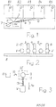
- Fig.1 shows in a very schematic representation of a view of a building G with five rooms R1 to R5, in each of which a device 1 is arranged, through which the in the temperature prevailing in each room is detected.
- a device 1 may advantageously be a sensor that detects only the actual value of the room temperature. But it can also be a sensor that detects both the actual value and the setpoint of the room temperature.
- a heating circuit manifold HK is also installed, to which pipes 2, 3, 4, 5 and 6 leading to the spaces R1 to R5 are connected, which are equipped with heating circuits arranged in the spaces R1 to R5
- the tubes 2 to 6 are connected.
- the tubes 2 to 6 are used to supply a heating medium, preferably water, to the heating circuits.
- a heating medium preferably water
- heating circuits for example surface heating systems, radiators or other heat exchangers can be installed in the spaces R1 to R5. It is also possible to arrange more than one heating circuit in a room. For each of these heating circuits then leads a separate pipe.
- the number of rooms of the building G is arbitrary. It can therefore be more or less than five rooms in the building G, each having at least one heating circuit.
- a regulator 7 is also arranged in the building G, which is preferably equipped with an electronic storage function.
- the controller 7 can be supplied from the devices 1 of the individual rooms signals, either wired or via radio.
- the signals of the devices 1, for example, correspond only to the actual value of the temperature prevailing in the respective room.
- the desired value of the temperature is then stored for each room of the building G in the memory of the controller 7.
- both the actual values and the setpoint values of the room temperature are transmitted to the controller 7 as signals.
- elements arranged in the heating circuit distributor HK are regulated in the sense of equalization. These elements are based on the FIGS. 2 and 3 explained.
- a valve V is mounted, which is provided with a in Fig. 3 is surrounded by a dash-dot line bordered actuator ST.
- the tubes 2 to 6 are connected to a main tube 8, which is supplied from a supply not shown with a heating medium.
- the following statements refer to a pipe, a valve and an actuator of a heating circuit. They apply in the same sense to all heating circuits.
- the actuator ST has a motor 9, which is connectable via a switch 10 with a voltage source 11.
- the shaft 12 of the motor 9 acts (with the interposition of a transmission) accordingly Fig. 3 on the plunger 13 of the valve V, which is thereby optionally adjusted in the direction of arrow 14.
- the valve V is thereby optionally brought into its closed position.
- the method according to the invention operates, for example, as follows:
- the temperatures in the rooms R1 to R5 are detected by the devices 1 as actual values.
- the associated setpoint values of the room temperatures are stored in the controller 7.
- the motor of the arranged in the tube 2 actuator ST is briefly supplied by closing the switch 10 with power.
- the plunger 13 of the valve V is thereby relieved and opposite to the direction of the arrow 14 moves, ie in the direction of the open position of the valve V.
- the supply of the heating medium to the heating circuit of the room R1 is thereby increased, so that the room temperature rises.
- the motor 9 is only briefly turned on, for example for 5 seconds, and then disconnected from the voltage source 11 again.
- This method described for a valve V or an actuator ST is carried out for all actuators of the heating circuit HK, one after the other only for one actuator each.
- the motors of all actuators are thus independent of each other in a predeterminable order by the controller 7 respectively for a short time Close the switch 10 connected to the voltage source 11 and accordingly supplied with power.
Landscapes
- Engineering & Computer Science (AREA)
- Physics & Mathematics (AREA)
- Thermal Sciences (AREA)
- Chemical & Material Sciences (AREA)
- Combustion & Propulsion (AREA)
- Mechanical Engineering (AREA)
- General Engineering & Computer Science (AREA)
- Remote Sensing (AREA)
- General Physics & Mathematics (AREA)
- Automation & Control Theory (AREA)
- Steam Or Hot-Water Central Heating Systems (AREA)
- Air Conditioning Control Device (AREA)
Claims (3)
- Procédé de régulation de la température de pièces d'un bâtiment (G), dans lequel est disposée une source de tension (11), un distributeur de circuit de chauffage (HK) étant installé dans le bâtiment (G), lequel présente un régulateur (7) et un nombre de soupapes (V) correspondant au nombre de circuits de chauffage prévus dans le bâtiment (G), une des soupapes étant à chaque fois intégrée dans une alimentation pour un fluide de chauffage ou de refroidissement d'un circuit de chauffage, chaque soupape (V) étant équipée d'un entraînement de réglage (ST) par le biais duquel la position de la soupape (V) déterminant le passage du fluide de chauffage ou de refroidissement est ajustée entre une position d'ouverture et une position de fermeture en tant que positions de fin de course, et un entraînement de réglage (ST) équipé d'un moteur électrique (9) étant utilisé en tant qu'entraînement de réglage pour chacune des soupapes (V), caractérisé en ce que- les moteurs (9) de tous les entraînements de réglage (ST) sont connectés à chaque fois individuellement et de manière séparée temporellement les uns des autres à la source de tension (11) avec la condition que seulement le moteur (9) d'un entraînement de réglage unique (ST) pour l'actionnement d'une soupape (V) par le régulateur (7) soit toujours raccordé à la source de tension (11) pendant une période de temps prédéfinie, et qu'à la fin de la période de temps, soit séparé de la source de tension (11) en conservant la position respective en tant que position stable, et- en ce que les moteurs (9) de tous les entraînements de réglage (ST) pour convertir le mouvement de rotation des rotors des moteurs (9) munis d'un arbre en un mouvement de translation sont équipés d'une transmission autobloquante.
- Procédé selon la revendication 1, caractérisé en ce que les températures de consigne prévues pour les pièces individuelles (R1 à R5) du bâtiment (G) sont mémorisées dans le régulateur (7).
- Procédé selon la revendication 1 ou 2, caractérisé en ce que les températures régnant dans les pièces individuelles (R1 à R5) sont transmises en tant que valeurs instantanées au régulateur (7) par des appareils (1) montés dans les pièces, détectant la température respective.
Priority Applications (3)
| Application Number | Priority Date | Filing Date | Title |
|---|---|---|---|
| ES14151038T ES2766073T3 (es) | 2014-01-14 | 2014-01-14 | Procedimiento para atemperar las habitaciones en un edificio |
| EP14151038.8A EP2894408B1 (fr) | 2014-01-14 | 2014-01-14 | Procédé de régulation de la température de pièces d'un bâtiment |
| DK14151038.8T DK2894408T3 (en) | 2014-01-14 | 2014-01-14 | Method for controlling the temperature in the rooms of a building |
Applications Claiming Priority (1)
| Application Number | Priority Date | Filing Date | Title |
|---|---|---|---|
| EP14151038.8A EP2894408B1 (fr) | 2014-01-14 | 2014-01-14 | Procédé de régulation de la température de pièces d'un bâtiment |
Publications (2)
| Publication Number | Publication Date |
|---|---|
| EP2894408A1 EP2894408A1 (fr) | 2015-07-15 |
| EP2894408B1 true EP2894408B1 (fr) | 2019-09-04 |
Family
ID=49949535
Family Applications (1)
| Application Number | Title | Priority Date | Filing Date |
|---|---|---|---|
| EP14151038.8A Active EP2894408B1 (fr) | 2014-01-14 | 2014-01-14 | Procédé de régulation de la température de pièces d'un bâtiment |
Country Status (3)
| Country | Link |
|---|---|
| EP (1) | EP2894408B1 (fr) |
| DK (1) | DK2894408T3 (fr) |
| ES (1) | ES2766073T3 (fr) |
Families Citing this family (2)
| Publication number | Priority date | Publication date | Assignee | Title |
|---|---|---|---|---|
| DE102017115376A1 (de) | 2017-07-10 | 2019-01-10 | Rehau Ag + Co | Verfahren zur Durchführung eines hydraulischen Abgleichs eines Heizungs- und/oder Kühlungssystems wie z. B. ein Gebäude |
| DE102018108562A1 (de) | 2018-04-11 | 2019-10-17 | Johnson Electric Germany GmbH & Co. KG | Stellantrieb, Heizkreisverteiler und Verfahren zur Montage des Stellantriebes in einem solchen Heizkreisverteiler |
Family Cites Families (6)
| Publication number | Priority date | Publication date | Assignee | Title |
|---|---|---|---|---|
| KR100924466B1 (ko) * | 2007-12-07 | 2009-11-03 | 주식회사 경동네트웍 | 난방환경에 적응하는 각방 실내온도 제어방법 |
| DE102008049619A1 (de) * | 2008-09-30 | 2010-04-01 | Simplex Armaturen + Fittings Gmbh | Gebäudeheizsystem |
| DE102008051275A1 (de) * | 2008-10-10 | 2010-04-15 | Möhlenhoff Wärmetechnik GmbH | Verfahren zur Temperierung von Räumen eines Gebäudes |
| DE102010024280B4 (de) * | 2010-06-18 | 2012-11-22 | Diehl Ako Stiftung & Co. Kg | Stellvorrichtung, insbesondere für ein Heizkörperventil |
| US8555926B2 (en) * | 2010-08-31 | 2013-10-15 | Malcolm MacDuff | Supply manifold for hydronic system |
| EP2530390B1 (fr) * | 2011-06-01 | 2013-07-24 | Danfoss A/S | Système de chauffage et procédé de chauffage de plusieurs pièces |
-
2014
- 2014-01-14 ES ES14151038T patent/ES2766073T3/es active Active
- 2014-01-14 DK DK14151038.8T patent/DK2894408T3/da active
- 2014-01-14 EP EP14151038.8A patent/EP2894408B1/fr active Active
Non-Patent Citations (1)
| Title |
|---|
| None * |
Also Published As
| Publication number | Publication date |
|---|---|
| DK2894408T3 (en) | 2021-09-27 |
| ES2766073T3 (es) | 2020-06-11 |
| EP2894408A1 (fr) | 2015-07-15 |
Similar Documents
| Publication | Publication Date | Title |
|---|---|---|
| DE102009004319A1 (de) | Verfahren, Computerprogramm und Regelgerät für einen temperaturbasierten hydraulischen Abgleich | |
| EP2676076A1 (fr) | Appareil de climatisation de local comprenant un appareil échangeur de chaleur liquide-air à éléments à effet peltier | |
| EP0893581A2 (fr) | Vanne à voies multiples | |
| DE102010005275A1 (de) | Verfahren und Vorrichtung zum Einstellen einer Temperiereinrichtung | |
| WO2008055551A1 (fr) | Installation de chauffage ou de réfrigération | |
| EP2435887B1 (fr) | Amelioration de la commande d'une vanne thermostatique | |
| DE2843929B2 (de) | Anordnung zur Steuerung der Raumtemperatur | |
| EP2175206B1 (fr) | Procédé d'équilibrage des températures de pièces d'un bâtiment | |
| DE102015114474A1 (de) | Wärmepumpenanlage und Verfahren zum Betrieb einer Wärmepumpenanlage | |
| EP2894408B1 (fr) | Procédé de régulation de la température de pièces d'un bâtiment | |
| DE102012015892A1 (de) | Verfahren zum Temperieren von Räumen eines Gebäudes | |
| DE102009051209A1 (de) | Einrichtung zur Temperaturregelung eines Raumes mit mindestens einer mit einem Wärmeträger betriebenen Heizeinrichtung | |
| DE102013225610A1 (de) | Luftklappenvorrichtung | |
| DE102008061239B4 (de) | Klimabeeinflussungssystem für Gebäude, insbesondere Temperaturbeeinflussungssystem | |
| DE1426936B1 (de) | Kuehlaggregat und dessen Steuerung | |
| DE2133812A1 (de) | Anordnung zum elektrischen einwirken auf stellglieder oder dergleichen | |
| DE102015113340A1 (de) | Heizungsanlage und Verfahren zum Betreiben einer Heizungsanlage | |
| DE2756860C3 (de) | Steuersystem fur die Heizungsanlage eines Mehrfamilienhauses | |
| DE102012022158B4 (de) | Raumluftklimaanlage mit einem Gebläse-Konvektor | |
| EP1116921A2 (fr) | Système de conditionnement d'air d'un local pour bâtiments | |
| EP3709121B1 (fr) | Borne plate de régulation permettant de réguler des dispositifs de chauffage ou de refroidissement dans des bâtiments | |
| DE3244603C1 (de) | Vorrichtung fuer Thermostatventile,insbesondere zur Temperaturabsenkung Thermostat-gesteuerter Heizkoerper | |
| DE19816165B4 (de) | Verfahren und Vorrichtung für die Inbetriebnahme einer Heizungsanlage | |
| DE720031C (de) | Regler fuer Waermeaustauscher von Klimaanlagen | |
| DE801102C (de) | Regeleinrichtung fuer Dampfheizungen, insbesondere fuer Niederdruckdampfheizungen von Eisenbahnwagen |
Legal Events
| Date | Code | Title | Description |
|---|---|---|---|
| PUAI | Public reference made under article 153(3) epc to a published international application that has entered the european phase |
Free format text: ORIGINAL CODE: 0009012 |
|
| 17P | Request for examination filed |
Effective date: 20140114 |
|
| AK | Designated contracting states |
Kind code of ref document: A1 Designated state(s): AL AT BE BG CH CY CZ DE DK EE ES FI FR GB GR HR HU IE IS IT LI LT LU LV MC MK MT NL NO PL PT RO RS SE SI SK SM TR |
|
| AX | Request for extension of the european patent |
Extension state: BA ME |
|
| R17P | Request for examination filed (corrected) |
Effective date: 20160420 |
|
| RBV | Designated contracting states (corrected) |
Designated state(s): AL AT BE BG CH CY CZ DE DK EE ES FI FR GB GR HR HU IE IS IT LI LT LU LV MC MK MT NL NO PL PT RO RS SE SI SK SM TR |
|
| RAP1 | Party data changed (applicant data changed or rights of an application transferred) |
Owner name: MOEHLENHOFF GMBH Owner name: EQ-3 ENTWICKLUNG GMBH |
|
| STAA | Information on the status of an ep patent application or granted ep patent |
Free format text: STATUS: EXAMINATION IS IN PROGRESS |
|
| 17Q | First examination report despatched |
Effective date: 20180919 |
|
| GRAP | Despatch of communication of intention to grant a patent |
Free format text: ORIGINAL CODE: EPIDOSNIGR1 |
|
| STAA | Information on the status of an ep patent application or granted ep patent |
Free format text: STATUS: GRANT OF PATENT IS INTENDED |
|
| INTG | Intention to grant announced |
Effective date: 20190402 |
|
| RAP1 | Party data changed (applicant data changed or rights of an application transferred) |
Owner name: MOEHLENHOFF GMBH Owner name: EQ-3 ENTWICKLUNG GMBH |
|
| RIN1 | Information on inventor provided before grant (corrected) |
Inventor name: DRESCHER, RAINER Inventor name: REDEKER, HEINZ-GERHARD |
|
| GRAS | Grant fee paid |
Free format text: ORIGINAL CODE: EPIDOSNIGR3 |
|
| GRAA | (expected) grant |
Free format text: ORIGINAL CODE: 0009210 |
|
| STAA | Information on the status of an ep patent application or granted ep patent |
Free format text: STATUS: THE PATENT HAS BEEN GRANTED |
|
| AK | Designated contracting states |
Kind code of ref document: B1 Designated state(s): AL AT BE BG CH CY CZ DE DK EE ES FI FR GB GR HR HU IE IS IT LI LT LU LV MC MK MT NL NO PL PT RO RS SE SI SK SM TR |
|
| REG | Reference to a national code |
Ref country code: GB Ref legal event code: FG4D Free format text: NOT ENGLISH |
|
| REG | Reference to a national code |
Ref country code: CH Ref legal event code: EP |
|
| REG | Reference to a national code |
Ref country code: AT Ref legal event code: REF Ref document number: 1175890 Country of ref document: AT Kind code of ref document: T Effective date: 20190915 |
|
| REG | Reference to a national code |
Ref country code: DE Ref legal event code: R096 Ref document number: 502014012547 Country of ref document: DE |
|
| REG | Reference to a national code |
Ref country code: IE Ref legal event code: FG4D Free format text: LANGUAGE OF EP DOCUMENT: GERMAN |
|
| REG | Reference to a national code |
Ref country code: NL Ref legal event code: MP Effective date: 20190904 |
|
| REG | Reference to a national code |
Ref country code: LT Ref legal event code: MG4D |
|
| PG25 | Lapsed in a contracting state [announced via postgrant information from national office to epo] |
Ref country code: NO Free format text: LAPSE BECAUSE OF FAILURE TO SUBMIT A TRANSLATION OF THE DESCRIPTION OR TO PAY THE FEE WITHIN THE PRESCRIBED TIME-LIMIT Effective date: 20191204 Ref country code: LT Free format text: LAPSE BECAUSE OF FAILURE TO SUBMIT A TRANSLATION OF THE DESCRIPTION OR TO PAY THE FEE WITHIN THE PRESCRIBED TIME-LIMIT Effective date: 20190904 Ref country code: FI Free format text: LAPSE BECAUSE OF FAILURE TO SUBMIT A TRANSLATION OF THE DESCRIPTION OR TO PAY THE FEE WITHIN THE PRESCRIBED TIME-LIMIT Effective date: 20190904 Ref country code: HR Free format text: LAPSE BECAUSE OF FAILURE TO SUBMIT A TRANSLATION OF THE DESCRIPTION OR TO PAY THE FEE WITHIN THE PRESCRIBED TIME-LIMIT Effective date: 20190904 Ref country code: SE Free format text: LAPSE BECAUSE OF FAILURE TO SUBMIT A TRANSLATION OF THE DESCRIPTION OR TO PAY THE FEE WITHIN THE PRESCRIBED TIME-LIMIT Effective date: 20190904 Ref country code: BG Free format text: LAPSE BECAUSE OF FAILURE TO SUBMIT A TRANSLATION OF THE DESCRIPTION OR TO PAY THE FEE WITHIN THE PRESCRIBED TIME-LIMIT Effective date: 20191204 |
|
| PG25 | Lapsed in a contracting state [announced via postgrant information from national office to epo] |
Ref country code: GR Free format text: LAPSE BECAUSE OF FAILURE TO SUBMIT A TRANSLATION OF THE DESCRIPTION OR TO PAY THE FEE WITHIN THE PRESCRIBED TIME-LIMIT Effective date: 20191205 Ref country code: RS Free format text: LAPSE BECAUSE OF FAILURE TO SUBMIT A TRANSLATION OF THE DESCRIPTION OR TO PAY THE FEE WITHIN THE PRESCRIBED TIME-LIMIT Effective date: 20190904 Ref country code: LV Free format text: LAPSE BECAUSE OF FAILURE TO SUBMIT A TRANSLATION OF THE DESCRIPTION OR TO PAY THE FEE WITHIN THE PRESCRIBED TIME-LIMIT Effective date: 20190904 Ref country code: ES Free format text: LAPSE BECAUSE OF FAILURE TO SUBMIT A TRANSLATION OF THE DESCRIPTION OR TO PAY THE FEE WITHIN THE PRESCRIBED TIME-LIMIT Effective date: 20190904 Ref country code: AL Free format text: LAPSE BECAUSE OF FAILURE TO SUBMIT A TRANSLATION OF THE DESCRIPTION OR TO PAY THE FEE WITHIN THE PRESCRIBED TIME-LIMIT Effective date: 20190904 |
|
| PG25 | Lapsed in a contracting state [announced via postgrant information from national office to epo] |
Ref country code: EE Free format text: LAPSE BECAUSE OF FAILURE TO SUBMIT A TRANSLATION OF THE DESCRIPTION OR TO PAY THE FEE WITHIN THE PRESCRIBED TIME-LIMIT Effective date: 20190904 Ref country code: PL Free format text: LAPSE BECAUSE OF FAILURE TO SUBMIT A TRANSLATION OF THE DESCRIPTION OR TO PAY THE FEE WITHIN THE PRESCRIBED TIME-LIMIT Effective date: 20190904 Ref country code: RO Free format text: LAPSE BECAUSE OF FAILURE TO SUBMIT A TRANSLATION OF THE DESCRIPTION OR TO PAY THE FEE WITHIN THE PRESCRIBED TIME-LIMIT Effective date: 20190904 Ref country code: NL Free format text: LAPSE BECAUSE OF FAILURE TO SUBMIT A TRANSLATION OF THE DESCRIPTION OR TO PAY THE FEE WITHIN THE PRESCRIBED TIME-LIMIT Effective date: 20190904 Ref country code: PT Free format text: LAPSE BECAUSE OF FAILURE TO SUBMIT A TRANSLATION OF THE DESCRIPTION OR TO PAY THE FEE WITHIN THE PRESCRIBED TIME-LIMIT Effective date: 20200106 |
|
| PG25 | Lapsed in a contracting state [announced via postgrant information from national office to epo] |
Ref country code: CZ Free format text: LAPSE BECAUSE OF FAILURE TO SUBMIT A TRANSLATION OF THE DESCRIPTION OR TO PAY THE FEE WITHIN THE PRESCRIBED TIME-LIMIT Effective date: 20190904 Ref country code: SK Free format text: LAPSE BECAUSE OF FAILURE TO SUBMIT A TRANSLATION OF THE DESCRIPTION OR TO PAY THE FEE WITHIN THE PRESCRIBED TIME-LIMIT Effective date: 20190904 Ref country code: SM Free format text: LAPSE BECAUSE OF FAILURE TO SUBMIT A TRANSLATION OF THE DESCRIPTION OR TO PAY THE FEE WITHIN THE PRESCRIBED TIME-LIMIT Effective date: 20190904 Ref country code: IS Free format text: LAPSE BECAUSE OF FAILURE TO SUBMIT A TRANSLATION OF THE DESCRIPTION OR TO PAY THE FEE WITHIN THE PRESCRIBED TIME-LIMIT Effective date: 20200224 |
|
| REG | Reference to a national code |
Ref country code: DE Ref legal event code: R097 Ref document number: 502014012547 Country of ref document: DE Ref country code: ES Ref legal event code: NE2A Effective date: 20200601 |
|
| REG | Reference to a national code |
Ref country code: ES Ref legal event code: FG2A Ref document number: 2766073 Country of ref document: ES Kind code of ref document: T3 Effective date: 20200611 |
|
| PLBE | No opposition filed within time limit |
Free format text: ORIGINAL CODE: 0009261 |
|
| STAA | Information on the status of an ep patent application or granted ep patent |
Free format text: STATUS: NO OPPOSITION FILED WITHIN TIME LIMIT |
|
| PG2D | Information on lapse in contracting state deleted |
Ref country code: IS |
|
| PG25 | Lapsed in a contracting state [announced via postgrant information from national office to epo] |
Ref country code: IS Free format text: LAPSE BECAUSE OF FAILURE TO SUBMIT A TRANSLATION OF THE DESCRIPTION OR TO PAY THE FEE WITHIN THE PRESCRIBED TIME-LIMIT Effective date: 20200105 Ref country code: ES Free format text: LAPSE BECAUSE OF FAILURE TO SUBMIT A TRANSLATION OF THE DESCRIPTION OR TO PAY THE FEE WITHIN THE PRESCRIBED TIME-LIMIT Effective date: 20190904 |
|
| PGRI | Patent reinstated in contracting state [announced from national office to epo] |
Ref country code: ES Effective date: 20200601 |
|
| 26N | No opposition filed |
Effective date: 20200605 |
|
| PG25 | Lapsed in a contracting state [announced via postgrant information from national office to epo] |
Ref country code: SI Free format text: LAPSE BECAUSE OF FAILURE TO SUBMIT A TRANSLATION OF THE DESCRIPTION OR TO PAY THE FEE WITHIN THE PRESCRIBED TIME-LIMIT Effective date: 20190904 Ref country code: MC Free format text: LAPSE BECAUSE OF FAILURE TO SUBMIT A TRANSLATION OF THE DESCRIPTION OR TO PAY THE FEE WITHIN THE PRESCRIBED TIME-LIMIT Effective date: 20190904 |
|
| REG | Reference to a national code |
Ref country code: SE Ref legal event code: TRGR Ref country code: SE Ref legal event code: RE72 Effective date: 20200924 |
|
| REG | Reference to a national code |
Ref country code: BE Ref legal event code: MM Effective date: 20200131 |
|
| PG25 | Lapsed in a contracting state [announced via postgrant information from national office to epo] |
Ref country code: LU Free format text: LAPSE BECAUSE OF NON-PAYMENT OF DUE FEES Effective date: 20200114 |
|
| PG25 | Lapsed in a contracting state [announced via postgrant information from national office to epo] |
Ref country code: BE Free format text: LAPSE BECAUSE OF NON-PAYMENT OF DUE FEES Effective date: 20200131 |
|
| PG25 | Lapsed in a contracting state [announced via postgrant information from national office to epo] |
Ref country code: IE Free format text: LAPSE BECAUSE OF NON-PAYMENT OF DUE FEES Effective date: 20200114 |
|
| PG25 | Lapsed in a contracting state [announced via postgrant information from national office to epo] |
Ref country code: SE Free format text: LAPSE BECAUSE OF FAILURE TO SUBMIT A TRANSLATION OF THE DESCRIPTION OR TO PAY THE FEE WITHIN THE PRESCRIBED TIME-LIMIT Effective date: 20190904 |
|
| PGRI | Patent reinstated in contracting state [announced from national office to epo] |
Ref country code: SE Effective date: 20200924 |
|
| REG | Reference to a national code |
Ref country code: DK Ref legal event code: T3 Effective date: 20210923 Ref country code: DK Ref legal event code: EGE Effective date: 20210923 |
|
| PG25 | Lapsed in a contracting state [announced via postgrant information from national office to epo] |
Ref country code: TR Free format text: LAPSE BECAUSE OF FAILURE TO SUBMIT A TRANSLATION OF THE DESCRIPTION OR TO PAY THE FEE WITHIN THE PRESCRIBED TIME-LIMIT Effective date: 20190904 Ref country code: MT Free format text: LAPSE BECAUSE OF FAILURE TO SUBMIT A TRANSLATION OF THE DESCRIPTION OR TO PAY THE FEE WITHIN THE PRESCRIBED TIME-LIMIT Effective date: 20190904 Ref country code: CY Free format text: LAPSE BECAUSE OF FAILURE TO SUBMIT A TRANSLATION OF THE DESCRIPTION OR TO PAY THE FEE WITHIN THE PRESCRIBED TIME-LIMIT Effective date: 20190904 |
|
| PG25 | Lapsed in a contracting state [announced via postgrant information from national office to epo] |
Ref country code: MK Free format text: LAPSE BECAUSE OF FAILURE TO SUBMIT A TRANSLATION OF THE DESCRIPTION OR TO PAY THE FEE WITHIN THE PRESCRIBED TIME-LIMIT Effective date: 20190904 |
|
| PGFP | Annual fee paid to national office [announced via postgrant information from national office to epo] |
Ref country code: CH Payment date: 20250201 Year of fee payment: 12 |
|
| REG | Reference to a national code |
Ref country code: CH Ref legal event code: U11 Free format text: ST27 STATUS EVENT CODE: U-0-0-U10-U11 (AS PROVIDED BY THE NATIONAL OFFICE) Effective date: 20260201 |
|
| PGFP | Annual fee paid to national office [announced via postgrant information from national office to epo] |
Ref country code: SE Payment date: 20260123 Year of fee payment: 13 |
|
| PGFP | Annual fee paid to national office [announced via postgrant information from national office to epo] |
Ref country code: GB Payment date: 20260121 Year of fee payment: 13 |
|
| PGFP | Annual fee paid to national office [announced via postgrant information from national office to epo] |
Ref country code: ES Payment date: 20260202 Year of fee payment: 13 |
|
| PGFP | Annual fee paid to national office [announced via postgrant information from national office to epo] |
Ref country code: DK Payment date: 20260121 Year of fee payment: 13 Ref country code: DE Payment date: 20260203 Year of fee payment: 13 |
|
| PGFP | Annual fee paid to national office [announced via postgrant information from national office to epo] |
Ref country code: AT Payment date: 20260115 Year of fee payment: 13 |
|
| PGFP | Annual fee paid to national office [announced via postgrant information from national office to epo] |
Ref country code: IT Payment date: 20260128 Year of fee payment: 13 |
|
| PGFP | Annual fee paid to national office [announced via postgrant information from national office to epo] |
Ref country code: FR Payment date: 20260125 Year of fee payment: 13 |