EP2894875B1 - Kopfhörer - Google Patents
Kopfhörer Download PDFInfo
- Publication number
- EP2894875B1 EP2894875B1 EP14176052.0A EP14176052A EP2894875B1 EP 2894875 B1 EP2894875 B1 EP 2894875B1 EP 14176052 A EP14176052 A EP 14176052A EP 2894875 B1 EP2894875 B1 EP 2894875B1
- Authority
- EP
- European Patent Office
- Prior art keywords
- headphone
- face
- press
- front cover
- sensor
- Prior art date
- Legal status (The legal status is an assumption and is not a legal conclusion. Google has not performed a legal analysis and makes no representation as to the accuracy of the status listed.)
- Active
Links
Images



Classifications
-
- H—ELECTRICITY
- H04—ELECTRIC COMMUNICATION TECHNIQUE
- H04R—LOUDSPEAKERS, MICROPHONES, GRAMOPHONE PICK-UPS OR LIKE ACOUSTIC ELECTROMECHANICAL TRANSDUCERS; ELECTRIC HEARING AIDS; PUBLIC ADDRESS SYSTEMS
- H04R1/00—Details of transducers, loudspeakers or microphones
- H04R1/10—Earpieces; Attachments therefor ; Earphones; Monophonic headphones
- H04R1/1058—Manufacture or assembly
-
- H—ELECTRICITY
- H04—ELECTRIC COMMUNICATION TECHNIQUE
- H04R—LOUDSPEAKERS, MICROPHONES, GRAMOPHONE PICK-UPS OR LIKE ACOUSTIC ELECTROMECHANICAL TRANSDUCERS; ELECTRIC HEARING AIDS; PUBLIC ADDRESS SYSTEMS
- H04R1/00—Details of transducers, loudspeakers or microphones
- H04R1/10—Earpieces; Attachments therefor ; Earphones; Monophonic headphones
- H04R1/1041—Mechanical or electronic switches, or control elements
-
- H—ELECTRICITY
- H04—ELECTRIC COMMUNICATION TECHNIQUE
- H04R—LOUDSPEAKERS, MICROPHONES, GRAMOPHONE PICK-UPS OR LIKE ACOUSTIC ELECTROMECHANICAL TRANSDUCERS; ELECTRIC HEARING AIDS; PUBLIC ADDRESS SYSTEMS
- H04R5/00—Stereophonic arrangements
- H04R5/033—Headphones for stereophonic communication
-
- H—ELECTRICITY
- H04—ELECTRIC COMMUNICATION TECHNIQUE
- H04R—LOUDSPEAKERS, MICROPHONES, GRAMOPHONE PICK-UPS OR LIKE ACOUSTIC ELECTROMECHANICAL TRANSDUCERS; ELECTRIC HEARING AIDS; PUBLIC ADDRESS SYSTEMS
- H04R1/00—Details of transducers, loudspeakers or microphones
- H04R1/10—Earpieces; Attachments therefor ; Earphones; Monophonic headphones
- H04R1/1008—Earpieces of the supra-aural or circum-aural type
-
- H—ELECTRICITY
- H04—ELECTRIC COMMUNICATION TECHNIQUE
- H04R—LOUDSPEAKERS, MICROPHONES, GRAMOPHONE PICK-UPS OR LIKE ACOUSTIC ELECTROMECHANICAL TRANSDUCERS; ELECTRIC HEARING AIDS; PUBLIC ADDRESS SYSTEMS
- H04R1/00—Details of transducers, loudspeakers or microphones
- H04R1/10—Earpieces; Attachments therefor ; Earphones; Monophonic headphones
- H04R1/1058—Manufacture or assembly
- H04R1/1066—Constructional aspects of the interconnection between earpiece and earpiece support
-
- H—ELECTRICITY
- H04—ELECTRIC COMMUNICATION TECHNIQUE
- H04R—LOUDSPEAKERS, MICROPHONES, GRAMOPHONE PICK-UPS OR LIKE ACOUSTIC ELECTROMECHANICAL TRANSDUCERS; ELECTRIC HEARING AIDS; PUBLIC ADDRESS SYSTEMS
- H04R2420/00—Details of connection covered by H04R, not provided for in its groups
- H04R2420/07—Applications of wireless loudspeakers or wireless microphones
-
- H—ELECTRICITY
- H04—ELECTRIC COMMUNICATION TECHNIQUE
- H04R—LOUDSPEAKERS, MICROPHONES, GRAMOPHONE PICK-UPS OR LIKE ACOUSTIC ELECTROMECHANICAL TRANSDUCERS; ELECTRIC HEARING AIDS; PUBLIC ADDRESS SYSTEMS
- H04R5/00—Stereophonic arrangements
- H04R5/033—Headphones for stereophonic communication
- H04R5/0335—Earpiece support, e.g. headbands or neckrests
Definitions
- the present invention generally relates to a headphone, and more particularly to a headphone capable of providing intelligent services.
- headphones are a preferable choice to listen to music, because of good sound field and sound insulation effects thereof.
- the headphone needs to be temporarily removed when the user is affected by surrounding environment during listening to music, while the music still keeps running in the meantime.
- the music played situation has changed and the feeling of the user for the music is inevitably influenced when the headphone is worn by the user again.
- FR2280283 discloses a headphone wherein the headband acts directly or indirectly on a contact in the earpiece supply cable and the contact is closed when the headband is tensioned, pushing down a button, and open when it is relaxed, to switch the earphones on and off.
- An electronic circuit can be mounted in one or both earpieces for reception by radio of RF signals from a radio or TV receiver. In such case the contact is inserted into the supply line to the above electronic receiving circuit and there are no wires connecting the earphones to the radio or TV receiver.
- US5144678 discloses a headset of a type which includes a pair of earmuff devices at opposite ends of a headband, which automatically switches an electronic circuit on or off when the headset is placed on the head or taken off, in a simple and rugged construction.
- Each earmuff device is of the type that includes a largely rigid housing and a soft resilient cushion mounted on the housing and designed to receive the ear of the wearer and press against the side of the wearer's head which surrounds his ear.
- a switch connected to the circuit includes an actuating device that is depressed and released along with the cushion.
- One type of switch is a mechanical type whose actuator device has a front end lying against a rear side of the cushion to be deflected and operate the switch when the cushion is rearwardly deflected during placement on the wearer's head.
- Another switch includes an electrically conductive element lying on the forward surface of the cushion to directly contact the wearer's skin and a detect sub-circuit which is responsive to the electrical potential of the wearer's body to switch the electronic circuit.
- An object of the present invention is to provide a headphone according to the subject-matter of claim 1.
- the headphone of the present invention utilizes the sensor module to detect whether the headphone is worn by the user, and then controls the actions of the headphone, such as music pause/start or power on/off. So the headphone of the present invention can provide intelligent services for users.
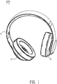
- a headphone 100 according to the present invention is shown and can provide intelligent services for users.
- the principle of the headphone 100 providing intelligent services is by sensing structural changes of the headphone 100 to detect whether the headphone 100 is being used.
- the headphone 100 has an elastic expansion for fitting the head of the user when it is worn by the user. So an elastic deformation will occur at a headband 1 and a joining structure 3 of the headphone 100 while wearing and taking off the headphone 100.
- the headphone 100 of the present invention detects usage states thereof by sensing the foregoing elastic deformation, and then automatically switches the headphone 100 according to the usage states.
- the headphone 100 includes a headphone assembly (not labeled) and a sensor module (not labeled) which is disposed in the headphone assembly and coupled with the headphone assembly, wherein the sensor module is used to sense the foregoing elastic deformation of the headphone 100.
- the headphone assembly includes a headband 1, a pair of ear components 2 and a pair of joining structures 3, wherein the ear components 2 are pivoted to two distal ends of the headband 1 by the joining structures 3 respectively.
- the sensor module includes an upper part (not labeled), a lower part (not labeled) spaced from and disposed opposite the upper part, and a press sensor P disposed between the upper part and the lower part, wherein the upper part and the lower part can be fitted to parts of the headphone assembly.
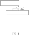
- the press sensor P has a sensing face T.
- the sensing face T of the press sensor P is spaced apart from and faces the upper part or the lower part when the headphone 100 is not in use (namely when the headphone 100 is not worn on the user's head).
- the upper part and the lower part are close to each other to contact the sensing face T and press the press sensor P.
- FIG. 3 it shows one design of the headphone 100 which is not according to the invention, wherein the sensor module is located in the headband 1.
- the headphone 100 uses the elasticity of the headband 1 to produce the desired displacement of the upper part and the lower part of the sensor module so as to contact the sensing face T and press the press sensor P.
- the headband 1 is substantially of U shape, and has a flexible headband 10 providing the upper part of the sensor module, and a headband cushion 11 providing the lower part of the sensor module.
- the flexible headband 10 is located above the headband cushion 11, and there is a space 12 between the flexible headband 10 and the headband cushion 11.
- the press sensor P is disposed on the inner side of the flexible headband 10 in the space 12, and the sensing face T of the press sensor P faces the headband cushion 11.
- the inner side of the headband cushion 11 is equipped with a contact part 13 located in the space 12 and facing the press sensor P.
- a gap is present between the contact part 13 and the sensing face T of the headband cushion 11.
- the headband cushion 11 is made of soft material such as rubber, and the contact part 13 is but not limited to a domed embossment or a plane structure.
- the press sensor P is also able to be disposed on the inner side of the headband cushion 11 in the space 12, and the contact part 13 is correspondingly disposed on the inner side of the flexible headband 10 and faces the sensing face T of the sensor module P.
- the headphone 100 could use the elasticity of the headband 1 to change the size of the space 12 between the flexible headband 10 and the headband cushion 11 so as to touch or disconnect from the sensing face T of the press sensor P.
- the headband cushion 11 is stretched by traction force of the two distal ends of the flexible headband 10 so as to make the contact part 13 touch the sensing face T, so that a contact signal is provided.
- the headband cushion 11 abuts against the user's head and the contact part 13 is directly pressed to touch the sensing face T so as to provide the contact signal.
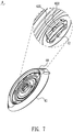
- FIGS. 4-7 they show an embodiment of the headphone 100 according to the invention, wherein the sensor module is located in the joining structure 3.
- the joining structure 3 is pivoted between the headband 1 and the ear component 2 to achieve a relative movement between the ear component 2 and the headband 1.
- the headphone 100 uses the relative movement at the joining structure 3 to touch the sensing face T so as to provide the contact signal from the press sensor P.
- a cover assembly at the connection of the headband 1 and the ear component 2 includes a front cover 4 and a rear cover 5 which provide the upper part and the lower part of the sensor module respectively.
- the front cover 4 and the rear cover 5 are pivotably coupled with each other by the joining structure 3, and the relative movement is allowed between the front cover 4 and the rear cover 5.
- the front cover 4 and the rear cover 5 have two face-to-face faces thereof designated as a first face 40 and a third face 50 respectively, and two opposite faces thereof designated as a second face 41 and a fourth face 51 respectively.
- the front cover 4 has a rectangular positioning portion 42 located in the middle thereof and protruding from the first face 40.
- the joining structure 3 includes a press plate 30 and a joint substrate 31.
- the press plate 30 has a hub 301, at least one cantilever beam 302 extending from an outside of the hub 301 along a direction perpendicular to the movement axis of the hub 301, and a wing plate 303 extending from a distal end of the cantilever beam 302.
- a pair of spaced guide holes 304 are opened in the wing plate 303.
- the joint substrate 31 is assembled in the positioning portion 42 of the front cover 4 through the second face 41.
- the joint substrate 31 and the front cover 4 together define a receiving chamber 421 penetrating through the middle of the joint substrate 31 and the middle of the positioning portion 42.
- At least one side of the receiving chamber 421 is further spread outward along a direction perpendicular to the movement axis of the hub 301 to form a receiving groove 422 corresponding to the cantilever beam 302 of the press plate 30.
- the receiving groove 422 is open at the top of the joint substrate 31 and penetrates upwards through the first face 40 and sideways through two sides of the joint substrate 31 and the positioning portion 42 along the extending direction thereof.
- the rear cover 5 defines a through hole 52 open in a middle thereof through the third face 50 and the fourth face 51 and corresponding to the positioning portion 42 of the front cover 4.
- the press plate 30 is assembled in the through hole 52 of the rear cover 5 via the fourth face 51.
- the wing plate 303 is located in the receiving lip 53 and the guide pillars 54 are inserted in the guide holes 304.
- the rear cover 5 is covered by the front cover 4 with the first face 40 being against the third face 50.
- the positioning portion 42 lies in the through hole 52 to receive the hub 301 of the press plate 30 in the receiving chamber 421 and locate the cantilever beam 302 in the receiving groove 422. Particularly, between the cantilever beam 302 and the receiving groove 422 and between the wing plate 303 and the receiving lip 53 a space must be retained for movement of the press plate 30.
- the hub 301 of the press plate 30 is locked to the joint substrate 31 and the wing plate 303 is restricted by the receiving lip 53, so as to locate the front cover 4 onto the rear cover 5.
- An elastic part S is disposed between the front cover 4 and the rear cover 5 for regulating relative angle and providing recoil stress between the front cover 4 and the rear cover 5.
- the elastic part S can be a spring, a gum-elastic, an elastic slice or other similar elements having elasticity along the movement axis of the front cover 4 with respect to the rear cover 5.
- the cooperation of the hub 301 of the press plate 30 and the receiving chamber 421 of the joint substrate 31 is for realizing a steady relative movement between the front cover 4 and the rear cover 5.
- the joint substrate 31 can be of spheroidal shape, of hemispheroidal shape, or of other shapes capable of realizing the pivotal movement between the front cover 4 and the rear cover 5.
- the joint substrate 31 and the positioning portion 42 of the front cover 4 can be moulded in one.
- the press sensor P is disposed (but not limited to) on the front cover 4, as long as the sensing face T lies between the front cover 4 and the rear cover 5 and faces the press plate 30.
- the contact signal from the press sensor P is provided by the relative movement of the front cover 4 and the rear cover 5 at the joining structure 3.
- the contact signals are sent to a transmitter-receiver device (not shown) by a control device (not shown) so as to control actions of the headphone 100, such as music pause/start or power on/off.
- the headphone 100 further includes a wireless transmitter-receiver device 6 for wirelessly receiving and transmitting the signals from the press sensor P.
- the wireless transmitter-receiver device 6 includes a control module 60, an antenna module 61 and a power module 62.
- the control module 60 is coupled with the press sensor P, the antenna module 61 and the power module 62, and utilizes power from the power module 62 and signals from the antenna module 61 to control the headphone assembly of the headphone 100.
- the control module 60 further controls the actions of the headphone 100, such as music pause/start or power on/off, after receiving the signals from the press sensor P.
- the antenna module 61 is preferably a Bluetooth antenna module.
- the press sensor P can be a piezoresistive press sensor, a ceramic press sensor, a diffused silicon press sensor, a sapphire press sensor or a sensor capable of producing digital signals through contact action.
- the press sensor P can also work to detect the usage states of the headphone 100 as follows.
- the sensing face T of the press sensor P is pressed by the inner parts of the headphone assembly.
- the inner parts of the headphone assembly generate deformation or movement to move the sensing face T of the press sensor P away from the inner parts of the headphone assembly.
- the headphone 100 of the present invention utilizes the sensor module to detect whether the headphone 100 is worn by the user, and then controls the actions of the headphone 100, such as music pause/start or power on/off. So the headphone 100 of the present invention can provide intelligent services for the users.
Landscapes
- Engineering & Computer Science (AREA)
- Physics & Mathematics (AREA)
- Acoustics & Sound (AREA)
- Signal Processing (AREA)
- Manufacturing & Machinery (AREA)
- Headphones And Earphones (AREA)
Claims (8)
- Kopfhörer (100), umfassend:eine Kopfhörerbaugruppe, enthaltend einen Kopfbügel (1), ein Paar Ohrkomponenten (2) und ein Paar Verbindungsstrukturen (3), wobei die Ohrkomponenten jeweils durch die Verbindungsstrukturen zu zwei jeweiligen distalen Enden des Kopfbügels geschwenkt werden; undein Sensormodul, das in der Kopfhörerbaugruppe angeordnet und mit der Kopfhörerbaugruppe gekoppelt ist, wobei das Sensormodul ein oberes Teil, ein von dem oberen Teil beabstandetes und gegenüber dem oberen Teil angeordnetes unteres Teil und einen zwischen dem oberen Teil und dem unteren Teil angeordneten Drucksensor enthält, wobei der Drucksensor (P) eine Sensorfläche (T) aufweist,wobei der Drucksensor dazu ausgelegt ist, Nutzungszustände des Kopfhörers zu erkennen, indem er beurteilt, ob aufgrund von elastischer Verformung oder Bewegung des oberen Teils und des unteren Teils, wenn der Benutzer den Kopfhörer trägt und absetzt, durch das obere Teil oder das untere Teil Druck auf seine Sensorfläche ausgeübt wird, wobei der Kopfhörer dazu ausgelegt ist, Signale von dem Drucksensor zur Steuerung seiner Aktionen zu verwenden,wobei die Sensorfläche (T) des Drucksensors (P) von dem jeweiligen oberen Teil oder unteren Teil beabstandet ist und zu diesem weist, wenn der Kopfhörer nicht auf dem Kopf des Benutzers getragen wird, wobei das obere Teil und das untere Teil im Verhältnis zueinander bewegbar sind, um die Sensorfläche zu berühren und den Drucksensor zu drücken,wobei sich das Sensormodul in der Verbindungsstruktur (3) der Kopfhörerbaugruppe befindet,dadurch gekennzeichnet, dass der Kopfhörer des Weiteren eine Abdeckungsbaugruppe an der Verbindung des Kopfbügels (1) und der Ohrkomponente (2) umfasst, die eine vordere Abdeckung (4) und eine hintere Abdeckung (5) enthält, welche das obere Teil beziehungsweise das untere Teil des Sensormoduls bilden, wobei die vordere Abdeckung und die hintere Abdeckung durch die Verbindungsstruktur (3) schwenkbar miteinander gekoppelt sind, um eine relative Bewegung zwischen ihnen zu ermöglichen, wobei der Drucksensor (P) so angeordnet ist, dass die Sensorfläche (T) zwischen der vorderen Abdeckung (4) und der hinteren Abdeckung (5) liegt, zum Berühren der oder Trennen von der vorderen Abdeckung oder der hinteren Abdeckung aufgrund der relativen Bewegung zwischen der vorderen Abdeckung und der hinteren Abdeckung,wobei die vordere Abdeckung (4) und die hintere Abdeckung (5) zwei einander zugewandte Stirnflächen von ihnen aufweisen, die als eine erste Stirnfläche (40) beziehungsweise eine dritte Stirnfläche (50) ausgewiesen sind, und zwei gegenüberliegende Stirnflächen von ihnen als eine zweite Stirnfläche (41) beziehungsweise eine vierte Stirnfläche (51) ausgewiesen sind, wobei die vordere Abdeckung einen Positionierungsabschnitt (42) aufweist, der von der ersten Stirnfläche (40) hervorsteht, die Verbindungsstruktur eine Druckplatte (30) und einen Verbindungsträger (31) enthält, die Druckplatte eine Nabe (301) und mindestens einen Kragarm (302) aufweist, der von einer Außenseite der Nabe entlang einer Richtung senkrecht zu einer Bewegungsachse der Nabe verläuft, der Verbindungsträger über die zweite Stirnfläche in dem Positionierungsabschnitt der vorderen Abdeckung montiert ist, der Verbindungsträger und die vordere Abdeckung zusammen eine aufnehmende Kammer (421) definieren, welche durch die Mitte des Verbindungsträgers und die Mitte des Positionierungsabschnitts penetriert, wobei mindestens eine Seite der aufnehmenden Kammer weiter nach außen ausgebreitet ist, um eine aufnehmende Nut (422) zu definieren, die dem Kragarm der Druckplatte entspricht, die hintere Abdeckung (5) ein Durchgangsloch (52) definiert, das dem Positionierungsabschnitt der vorderen Abdeckung entspricht, die Druckplatte in dem Durchgangsloch der hinteren Abdeckung montiert ist, die hintere Abdeckung die vordere Abdeckung abdeckt, wobei die erste Stirnfläche (40) an der dritten Stirnfläche (50) anliegt, der Positionierungsabschnitt (42) in dem Durchgangsloch liegt, um die Nabe der Druckplatte in der aufnehmenden Kammer aufzunehmen und den Kragarm mit einem Abstand zwischen dem Kragarm und der aufnehmenden Nut in der aufnehmenden Nut zu positionieren.
- Kopfhörer (100) nach Anspruch 1, wobei zwischen der vorderen Abdeckung (4) und der hinteren Abdeckung (5) ein elastisches Teil (S) angeordnet ist, um den relativen Winkel zu regulieren und für Rückprallbelastung zwischen der vorderen Abdeckung und der hinteren Abdeckung zu sorgen.
- Kopfhörer (100) nach Anspruch 2, wobei das elastische Teil (S) aus einer Feder, einem elastischen Gummi, einer elastischen Scheibe oder aus anderen ähnlichen Elementen besteht, die Elastizität entlang der Bewegungsachse der vorderen Abdeckung (4) im Hinblick auf die hintere Abdeckung (5) aufweisen.
- Kopfhörer (100) nach Anspruch 1, wobei sich ein distales Ende des Kragarms (302) erweitert, um eine Flügelplatte (303) zu bilden, ein Paar aufnehmender Lippen (53) an zwei Seiten des Durchgangslochs (52) durch die vierte Stirnfläche liegen und den Flügelplatten (303) der Druckplatte entsprechen, die Flügelplatte mit einem Abstand zwischen der Flügelplatte und der aufnehmenden Lippe in der aufnehmenden Lippe angeordnet ist.
- Kopfhörer (100) nach Anspruch 4, wobei ein Paar beabstandeter Führungslöcher (304) in der Flügelplatte offen sind und ein Paar Führungssäulen (54) auf einer inneren Seitenwand von jeder empfangenden Lippe hervorstehen und den Führungslöchern der Flügelplatte entsprechen, wobei die Führungssäulen in die Führungslöcher eingeführt werden.
- Kopfhörer (100) nach Anspruch 1, wobei der Verbindungsträger (31) und der Positionierungsabschnitt der vorderen Abdeckung in einem Stück geformt sind.
- Kopfhörer (100) nach Anspruch 1, des Weiteren umfassend eine drahtlose Sender-Empfänger-Einrichtung (6) zum drahtlosen Empfangen und Senden der Signale von dem Drucksensor (P), wobei die drahtlose Sender-Empfänger-Einrichtung ein Steuerungsmodul (60), ein Antennenmodul (61) und ein Stromversorgungsmodul (62) enthält, das Steuerungsmodul mit dem Drucksensor, dem Antennenmodul und dem Stromversorgungsmodul gekoppelt ist, wobei das Steuerungsmodul dazu ausgelegt ist, die Aktionen des Kopfhörers zu steuern, nachdem es die Signale von dem Drucksensor empfangen hat.
- Kopfhörer (100) nach Anspruch 1, wobei der Drucksensor ein piezoresistiver Drucksensor, ein keramischer Drucksensor, ein diffundierter Silizium-Drucksensor, ein Saphir-Drucksensor oder ein Sensor ist, der in der Lage ist, durch Berührungsaktion digitale Signale zu erzeugen.
Applications Claiming Priority (1)
| Application Number | Priority Date | Filing Date | Title |
|---|---|---|---|
| TW103200631U TWM477745U (zh) | 2014-01-10 | 2014-01-10 | 頭戴耳機 |
Publications (2)
| Publication Number | Publication Date |
|---|---|
| EP2894875A1 EP2894875A1 (de) | 2015-07-15 |
| EP2894875B1 true EP2894875B1 (de) | 2019-02-20 |
Family
ID=51295144
Family Applications (1)
| Application Number | Title | Priority Date | Filing Date |
|---|---|---|---|
| EP14176052.0A Active EP2894875B1 (de) | 2014-01-10 | 2014-07-08 | Kopfhörer |
Country Status (4)
| Country | Link |
|---|---|
| US (1) | US9137598B2 (de) |
| EP (1) | EP2894875B1 (de) |
| JP (1) | JP3192879U (de) |
| TW (1) | TWM477745U (de) |
Families Citing this family (12)
| Publication number | Priority date | Publication date | Assignee | Title |
|---|---|---|---|---|
| JP2012079082A (ja) * | 2010-10-01 | 2012-04-19 | Sony Corp | 入力装置 |
| KR101757843B1 (ko) | 2015-06-12 | 2017-07-14 | 조재희 | 헤드폰용 유체 분사장치 |
| US11172281B2 (en) | 2015-07-31 | 2021-11-09 | Harman International Industries, Incorporated | Self-adjusting head-mounted audio device |
| KR20180116759A (ko) * | 2017-04-17 | 2018-10-25 | 헤드셋, 엘엘씨 | 헤드셋 액세서리 |
| US10015576B1 (en) * | 2017-11-12 | 2018-07-03 | Keith Mungin | Headphones with coordinated external illumination |
| US10440462B1 (en) * | 2018-03-27 | 2019-10-08 | Cheng Uei Precision Industry Co., Ltd. | Earphone assembly and sound channel control method applied therein |
| CN109451389B (zh) * | 2018-12-25 | 2024-10-15 | 歌尔科技有限公司 | 一种头戴式无线耳机及其佩戴检测装置 |
| JP7340800B2 (ja) | 2019-08-09 | 2023-09-08 | パナソニックIpマネジメント株式会社 | ワイヤレスイヤホン |
| TWI740277B (zh) * | 2019-11-19 | 2021-09-21 | 美律實業股份有限公司 | 耳機裝置 |
| CN112188343B (zh) * | 2020-09-28 | 2022-09-20 | 歌尔科技有限公司 | 无线耳机及其佩戴检测方法、存储介质 |
| EP4018984A1 (de) * | 2020-12-23 | 2022-06-29 | 3M Innovative Properties Company | Gehörschutz mit sensormodul und verfahren zum nachrüsten eines gehörschutzes mit einem sensormodul |
| CN114979871B (zh) * | 2021-02-24 | 2023-12-08 | 华为技术有限公司 | 一种耳机 |
Family Cites Families (8)
| Publication number | Priority date | Publication date | Assignee | Title |
|---|---|---|---|---|
| US2946860A (en) * | 1957-01-03 | 1960-07-26 | Rca Corp | Headset |
| DE2435552B2 (de) * | 1974-07-24 | 1976-07-22 | Loewe Opta Gmbh, 1000 Berlin | Kopfhoerer |
| US5144678A (en) * | 1991-02-04 | 1992-09-01 | Golden West Communications Inc. | Automatically switched headset |
| US20060083397A1 (en) * | 2004-10-19 | 2006-04-20 | Obo Pro.2 Inc. | Wireless headphone with a self-actuated switch |
| US8134593B2 (en) * | 2006-11-22 | 2012-03-13 | Nikon Corporation | Output device |
| US8855719B2 (en) * | 2009-05-08 | 2014-10-07 | Kopin Corporation | Wireless hands-free computing headset with detachable accessories controllable by motion, body gesture and/or vocal commands |
| US20140016795A1 (en) * | 2012-07-10 | 2014-01-16 | Closeout Solutions, Llc | Personalized headphones and method of personalizing audio output |
| US20140064500A1 (en) * | 2012-08-30 | 2014-03-06 | Monster | Automatic Power Adjusting Headphones |
-
2014
- 2014-01-10 TW TW103200631U patent/TWM477745U/zh not_active IP Right Cessation
- 2014-06-26 JP JP2014003353U patent/JP3192879U/ja not_active Expired - Lifetime
- 2014-06-30 US US14/319,838 patent/US9137598B2/en active Active
- 2014-07-08 EP EP14176052.0A patent/EP2894875B1/de active Active
Non-Patent Citations (1)
| Title |
|---|
| None * |
Also Published As
| Publication number | Publication date |
|---|---|
| JP3192879U (ja) | 2014-09-04 |
| US9137598B2 (en) | 2015-09-15 |
| US20150201268A1 (en) | 2015-07-16 |
| EP2894875A1 (de) | 2015-07-15 |
| TWM477745U (zh) | 2014-05-01 |
Similar Documents
| Publication | Publication Date | Title |
|---|---|---|
| EP2894875B1 (de) | Kopfhörer | |
| KR101835337B1 (ko) | 휴대용 음향기기 | |
| EP3236638B1 (de) | Tragbare elektronische ausrüstung | |
| CA2576615C (en) | Body radiation and conductivity in rf communication | |
| WO2020140445A1 (zh) | 一种扬声装置 | |
| CN107041169B (zh) | 具有光学传感器的耳机设备 | |
| US8965029B2 (en) | Headphone | |
| US12058487B2 (en) | Sound output device | |
| JP2023156517A (ja) | 生体情報測定装置 | |
| US20230345162A1 (en) | Headphones with a curved mesh headband | |
| US20090095605A1 (en) | Switch assembly and earphone set with the same | |
| CN211909097U (zh) | 一种骨传导耳机 | |
| JP2013135266A (ja) | ヘッドホン装置 | |
| JPWO2011007448A1 (ja) | イヤホン及び電子機器 | |
| CN117714923A (zh) | 耳机和通过耳机执行命令的方法 | |
| CN205566588U (zh) | 一种具有旋转开关结构的头戴式耳机 | |
| KR101796623B1 (ko) | 골전도 귀마개 | |
| JP7204224B2 (ja) | 聴音装置 | |
| US11805353B2 (en) | Headphone | |
| CN222981647U (zh) | 耳机 | |
| CN223463106U (zh) | 一种耳机盒及无线通讯设备 | |
| JP2014045514A (ja) | イヤホン | |
| CN222602552U (zh) | 一种带噪声显示的蓝牙头戴式防护耳机 | |
| CN121357453A (zh) | 耳机 | |
| KR101625300B1 (ko) | 이어폰 |
Legal Events
| Date | Code | Title | Description |
|---|---|---|---|
| PUAI | Public reference made under article 153(3) epc to a published international application that has entered the european phase |
Free format text: ORIGINAL CODE: 0009012 |
|
| 17P | Request for examination filed |
Effective date: 20140708 |
|
| AK | Designated contracting states |
Kind code of ref document: A1 Designated state(s): AL AT BE BG CH CY CZ DE DK EE ES FI FR GB GR HR HU IE IS IT LI LT LU LV MC MK MT NL NO PL PT RO RS SE SI SK SM TR |
|
| AX | Request for extension of the european patent |
Extension state: BA ME |
|
| RBV | Designated contracting states (corrected) |
Designated state(s): AL AT BE BG CH CY CZ DE DK EE ES FI FR GB GR HR HU IE IS IT LI LT LU LV MC MK MT NL NO PL PT RO RS SE SI SK SM TR |
|
| STAA | Information on the status of an ep patent application or granted ep patent |
Free format text: STATUS: EXAMINATION IS IN PROGRESS |
|
| 17Q | First examination report despatched |
Effective date: 20180628 |
|
| GRAP | Despatch of communication of intention to grant a patent |
Free format text: ORIGINAL CODE: EPIDOSNIGR1 |
|
| STAA | Information on the status of an ep patent application or granted ep patent |
Free format text: STATUS: GRANT OF PATENT IS INTENDED |
|
| RIC1 | Information provided on ipc code assigned before grant |
Ipc: H04R 1/10 20060101AFI20181017BHEP Ipc: H04R 5/033 20060101ALI20181017BHEP |
|
| INTG | Intention to grant announced |
Effective date: 20181121 |
|
| GRAS | Grant fee paid |
Free format text: ORIGINAL CODE: EPIDOSNIGR3 |
|
| GRAA | (expected) grant |
Free format text: ORIGINAL CODE: 0009210 |
|
| STAA | Information on the status of an ep patent application or granted ep patent |
Free format text: STATUS: THE PATENT HAS BEEN GRANTED |
|
| AK | Designated contracting states |
Kind code of ref document: B1 Designated state(s): AL AT BE BG CH CY CZ DE DK EE ES FI FR GB GR HR HU IE IS IT LI LT LU LV MC MK MT NL NO PL PT RO RS SE SI SK SM TR |
|
| REG | Reference to a national code |
Ref country code: GB Ref legal event code: FG4D |
|
| REG | Reference to a national code |
Ref country code: CH Ref legal event code: EP |
|
| REG | Reference to a national code |
Ref country code: DE Ref legal event code: R096 Ref document number: 602014041159 Country of ref document: DE |
|
| REG | Reference to a national code |
Ref country code: AT Ref legal event code: REF Ref document number: 1099801 Country of ref document: AT Kind code of ref document: T Effective date: 20190315 |
|
| REG | Reference to a national code |
Ref country code: IE Ref legal event code: FG4D |
|
| REG | Reference to a national code |
Ref country code: NL Ref legal event code: MP Effective date: 20190220 |
|
| REG | Reference to a national code |
Ref country code: LT Ref legal event code: MG4D |
|
| PG25 | Lapsed in a contracting state [announced via postgrant information from national office to epo] |
Ref country code: LT Free format text: LAPSE BECAUSE OF FAILURE TO SUBMIT A TRANSLATION OF THE DESCRIPTION OR TO PAY THE FEE WITHIN THE PRESCRIBED TIME-LIMIT Effective date: 20190220 Ref country code: NL Free format text: LAPSE BECAUSE OF FAILURE TO SUBMIT A TRANSLATION OF THE DESCRIPTION OR TO PAY THE FEE WITHIN THE PRESCRIBED TIME-LIMIT Effective date: 20190220 Ref country code: NO Free format text: LAPSE BECAUSE OF FAILURE TO SUBMIT A TRANSLATION OF THE DESCRIPTION OR TO PAY THE FEE WITHIN THE PRESCRIBED TIME-LIMIT Effective date: 20190520 Ref country code: SE Free format text: LAPSE BECAUSE OF FAILURE TO SUBMIT A TRANSLATION OF THE DESCRIPTION OR TO PAY THE FEE WITHIN THE PRESCRIBED TIME-LIMIT Effective date: 20190220 Ref country code: PT Free format text: LAPSE BECAUSE OF FAILURE TO SUBMIT A TRANSLATION OF THE DESCRIPTION OR TO PAY THE FEE WITHIN THE PRESCRIBED TIME-LIMIT Effective date: 20190620 Ref country code: FI Free format text: LAPSE BECAUSE OF FAILURE TO SUBMIT A TRANSLATION OF THE DESCRIPTION OR TO PAY THE FEE WITHIN THE PRESCRIBED TIME-LIMIT Effective date: 20190220 |
|
| PG25 | Lapsed in a contracting state [announced via postgrant information from national office to epo] |
Ref country code: BG Free format text: LAPSE BECAUSE OF FAILURE TO SUBMIT A TRANSLATION OF THE DESCRIPTION OR TO PAY THE FEE WITHIN THE PRESCRIBED TIME-LIMIT Effective date: 20190520 Ref country code: RS Free format text: LAPSE BECAUSE OF FAILURE TO SUBMIT A TRANSLATION OF THE DESCRIPTION OR TO PAY THE FEE WITHIN THE PRESCRIBED TIME-LIMIT Effective date: 20190220 Ref country code: LV Free format text: LAPSE BECAUSE OF FAILURE TO SUBMIT A TRANSLATION OF THE DESCRIPTION OR TO PAY THE FEE WITHIN THE PRESCRIBED TIME-LIMIT Effective date: 20190220 Ref country code: IS Free format text: LAPSE BECAUSE OF FAILURE TO SUBMIT A TRANSLATION OF THE DESCRIPTION OR TO PAY THE FEE WITHIN THE PRESCRIBED TIME-LIMIT Effective date: 20190620 Ref country code: GR Free format text: LAPSE BECAUSE OF FAILURE TO SUBMIT A TRANSLATION OF THE DESCRIPTION OR TO PAY THE FEE WITHIN THE PRESCRIBED TIME-LIMIT Effective date: 20190521 Ref country code: HR Free format text: LAPSE BECAUSE OF FAILURE TO SUBMIT A TRANSLATION OF THE DESCRIPTION OR TO PAY THE FEE WITHIN THE PRESCRIBED TIME-LIMIT Effective date: 20190220 |
|
| REG | Reference to a national code |
Ref country code: AT Ref legal event code: MK05 Ref document number: 1099801 Country of ref document: AT Kind code of ref document: T Effective date: 20190220 |
|
| PG25 | Lapsed in a contracting state [announced via postgrant information from national office to epo] |
Ref country code: ES Free format text: LAPSE BECAUSE OF FAILURE TO SUBMIT A TRANSLATION OF THE DESCRIPTION OR TO PAY THE FEE WITHIN THE PRESCRIBED TIME-LIMIT Effective date: 20190220 Ref country code: DK Free format text: LAPSE BECAUSE OF FAILURE TO SUBMIT A TRANSLATION OF THE DESCRIPTION OR TO PAY THE FEE WITHIN THE PRESCRIBED TIME-LIMIT Effective date: 20190220 Ref country code: SK Free format text: LAPSE BECAUSE OF FAILURE TO SUBMIT A TRANSLATION OF THE DESCRIPTION OR TO PAY THE FEE WITHIN THE PRESCRIBED TIME-LIMIT Effective date: 20190220 Ref country code: AL Free format text: LAPSE BECAUSE OF FAILURE TO SUBMIT A TRANSLATION OF THE DESCRIPTION OR TO PAY THE FEE WITHIN THE PRESCRIBED TIME-LIMIT Effective date: 20190220 Ref country code: EE Free format text: LAPSE BECAUSE OF FAILURE TO SUBMIT A TRANSLATION OF THE DESCRIPTION OR TO PAY THE FEE WITHIN THE PRESCRIBED TIME-LIMIT Effective date: 20190220 Ref country code: IT Free format text: LAPSE BECAUSE OF FAILURE TO SUBMIT A TRANSLATION OF THE DESCRIPTION OR TO PAY THE FEE WITHIN THE PRESCRIBED TIME-LIMIT Effective date: 20190220 Ref country code: CZ Free format text: LAPSE BECAUSE OF FAILURE TO SUBMIT A TRANSLATION OF THE DESCRIPTION OR TO PAY THE FEE WITHIN THE PRESCRIBED TIME-LIMIT Effective date: 20190220 Ref country code: RO Free format text: LAPSE BECAUSE OF FAILURE TO SUBMIT A TRANSLATION OF THE DESCRIPTION OR TO PAY THE FEE WITHIN THE PRESCRIBED TIME-LIMIT Effective date: 20190220 |
|
| REG | Reference to a national code |
Ref country code: DE Ref legal event code: R097 Ref document number: 602014041159 Country of ref document: DE |
|
| PG25 | Lapsed in a contracting state [announced via postgrant information from national office to epo] |
Ref country code: SM Free format text: LAPSE BECAUSE OF FAILURE TO SUBMIT A TRANSLATION OF THE DESCRIPTION OR TO PAY THE FEE WITHIN THE PRESCRIBED TIME-LIMIT Effective date: 20190220 Ref country code: PL Free format text: LAPSE BECAUSE OF FAILURE TO SUBMIT A TRANSLATION OF THE DESCRIPTION OR TO PAY THE FEE WITHIN THE PRESCRIBED TIME-LIMIT Effective date: 20190220 |
|
| PLBE | No opposition filed within time limit |
Free format text: ORIGINAL CODE: 0009261 |
|
| STAA | Information on the status of an ep patent application or granted ep patent |
Free format text: STATUS: NO OPPOSITION FILED WITHIN TIME LIMIT |
|
| PG25 | Lapsed in a contracting state [announced via postgrant information from national office to epo] |
Ref country code: AT Free format text: LAPSE BECAUSE OF FAILURE TO SUBMIT A TRANSLATION OF THE DESCRIPTION OR TO PAY THE FEE WITHIN THE PRESCRIBED TIME-LIMIT Effective date: 20190220 |
|
| 26N | No opposition filed |
Effective date: 20191121 |
|
| PG25 | Lapsed in a contracting state [announced via postgrant information from national office to epo] |
Ref country code: MC Free format text: LAPSE BECAUSE OF FAILURE TO SUBMIT A TRANSLATION OF THE DESCRIPTION OR TO PAY THE FEE WITHIN THE PRESCRIBED TIME-LIMIT Effective date: 20190220 Ref country code: SI Free format text: LAPSE BECAUSE OF FAILURE TO SUBMIT A TRANSLATION OF THE DESCRIPTION OR TO PAY THE FEE WITHIN THE PRESCRIBED TIME-LIMIT Effective date: 20190220 |
|
| REG | Reference to a national code |
Ref country code: CH Ref legal event code: PL |
|
| PG25 | Lapsed in a contracting state [announced via postgrant information from national office to epo] |
Ref country code: TR Free format text: LAPSE BECAUSE OF FAILURE TO SUBMIT A TRANSLATION OF THE DESCRIPTION OR TO PAY THE FEE WITHIN THE PRESCRIBED TIME-LIMIT Effective date: 20190220 |
|
| REG | Reference to a national code |
Ref country code: BE Ref legal event code: MM Effective date: 20190731 |
|
| PG25 | Lapsed in a contracting state [announced via postgrant information from national office to epo] |
Ref country code: CH Free format text: LAPSE BECAUSE OF NON-PAYMENT OF DUE FEES Effective date: 20190731 Ref country code: BE Free format text: LAPSE BECAUSE OF NON-PAYMENT OF DUE FEES Effective date: 20190731 Ref country code: LI Free format text: LAPSE BECAUSE OF NON-PAYMENT OF DUE FEES Effective date: 20190731 Ref country code: LU Free format text: LAPSE BECAUSE OF NON-PAYMENT OF DUE FEES Effective date: 20190708 |
|
| PG25 | Lapsed in a contracting state [announced via postgrant information from national office to epo] |
Ref country code: IE Free format text: LAPSE BECAUSE OF NON-PAYMENT OF DUE FEES Effective date: 20190708 |
|
| PG25 | Lapsed in a contracting state [announced via postgrant information from national office to epo] |
Ref country code: CY Free format text: LAPSE BECAUSE OF FAILURE TO SUBMIT A TRANSLATION OF THE DESCRIPTION OR TO PAY THE FEE WITHIN THE PRESCRIBED TIME-LIMIT Effective date: 20190220 |
|
| PG25 | Lapsed in a contracting state [announced via postgrant information from national office to epo] |
Ref country code: HU Free format text: LAPSE BECAUSE OF FAILURE TO SUBMIT A TRANSLATION OF THE DESCRIPTION OR TO PAY THE FEE WITHIN THE PRESCRIBED TIME-LIMIT; INVALID AB INITIO Effective date: 20140708 Ref country code: MT Free format text: LAPSE BECAUSE OF FAILURE TO SUBMIT A TRANSLATION OF THE DESCRIPTION OR TO PAY THE FEE WITHIN THE PRESCRIBED TIME-LIMIT Effective date: 20190220 |
|
| REG | Reference to a national code |
Ref country code: DE Ref legal event code: R082 Ref document number: 602014041159 Country of ref document: DE Representative=s name: BAUER WAGNER PELLENGAHR SROKA PATENT- & RECHTS, DE Ref country code: DE Ref legal event code: R082 Ref document number: 602014041159 Country of ref document: DE Representative=s name: BAUER PSU PARTG MBB, DE |
|
| PG25 | Lapsed in a contracting state [announced via postgrant information from national office to epo] |
Ref country code: MK Free format text: LAPSE BECAUSE OF FAILURE TO SUBMIT A TRANSLATION OF THE DESCRIPTION OR TO PAY THE FEE WITHIN THE PRESCRIBED TIME-LIMIT Effective date: 20190220 |
|
| PGFP | Annual fee paid to national office [announced via postgrant information from national office to epo] |
Ref country code: GB Payment date: 20250602 Year of fee payment: 12 |
|
| PGFP | Annual fee paid to national office [announced via postgrant information from national office to epo] |
Ref country code: FR Payment date: 20250602 Year of fee payment: 12 |
|
| PGFP | Annual fee paid to national office [announced via postgrant information from national office to epo] |
Ref country code: DE Payment date: 20250605 Year of fee payment: 12 |