EP2895357B1 - Pare-choc de véhicule comprenant un appareil de détection de collision avec un piéton - Google Patents
Pare-choc de véhicule comprenant un appareil de détection de collision avec un piéton Download PDFInfo
- Publication number
- EP2895357B1 EP2895357B1 EP13824335.7A EP13824335A EP2895357B1 EP 2895357 B1 EP2895357 B1 EP 2895357B1 EP 13824335 A EP13824335 A EP 13824335A EP 2895357 B1 EP2895357 B1 EP 2895357B1
- Authority
- EP
- European Patent Office
- Prior art keywords
- vehicle
- bumper
- chamber member
- width direction
- projected
- Prior art date
- Legal status (The legal status is an assumption and is not a legal conclusion. Google has not performed a legal analysis and makes no representation as to the accuracy of the status listed.)
- Not-in-force
Links
- 238000001514 detection method Methods 0.000 title claims description 11
- 239000006096 absorbing agent Substances 0.000 claims description 35
- 230000002787 reinforcement Effects 0.000 claims description 15
- 239000000463 material Substances 0.000 description 6
- 125000006850 spacer group Chemical group 0.000 description 6
- 239000011347 resin Substances 0.000 description 5
- 229920005989 resin Polymers 0.000 description 5
- 238000005187 foaming Methods 0.000 description 3
- 239000003550 marker Substances 0.000 description 3
- 238000005452 bending Methods 0.000 description 2
- 230000015556 catabolic process Effects 0.000 description 2
- 238000006731 degradation reaction Methods 0.000 description 2
- JOYRKODLDBILNP-UHFFFAOYSA-N Ethyl urethane Chemical compound CCOC(N)=O JOYRKODLDBILNP-UHFFFAOYSA-N 0.000 description 1
- CWYNVVGOOAEACU-UHFFFAOYSA-N Fe2+ Chemical compound [Fe+2] CWYNVVGOOAEACU-UHFFFAOYSA-N 0.000 description 1
- 229910052782 aluminium Inorganic materials 0.000 description 1
- XAGFODPZIPBFFR-UHFFFAOYSA-N aluminium Chemical compound [Al] XAGFODPZIPBFFR-UHFFFAOYSA-N 0.000 description 1
- 230000000694 effects Effects 0.000 description 1
- 239000006260 foam Substances 0.000 description 1
- 239000007769 metal material Substances 0.000 description 1
Images


Classifications
-
- B—PERFORMING OPERATIONS; TRANSPORTING
- B60—VEHICLES IN GENERAL
- B60R—VEHICLES, VEHICLE FITTINGS, OR VEHICLE PARTS, NOT OTHERWISE PROVIDED FOR
- B60R19/00—Wheel guards; Radiator guards, e.g. grilles; Obstruction removers; Fittings damping bouncing force in collisions
- B60R19/02—Bumpers, i.e. impact receiving or absorbing members for protecting vehicles or fending off blows from other vehicles or objects
- B60R19/023—Details
-
- B—PERFORMING OPERATIONS; TRANSPORTING
- B60—VEHICLES IN GENERAL
- B60R—VEHICLES, VEHICLE FITTINGS, OR VEHICLE PARTS, NOT OTHERWISE PROVIDED FOR
- B60R21/00—Arrangements or fittings on vehicles for protecting or preventing injuries to occupants or pedestrians in case of accidents or other traffic risks
- B60R21/01—Electrical circuits for triggering passive safety arrangements, e.g. airbags, safety belt tighteners, in case of vehicle accidents or impending vehicle accidents
- B60R21/013—Electrical circuits for triggering passive safety arrangements, e.g. airbags, safety belt tighteners, in case of vehicle accidents or impending vehicle accidents including means for detecting collisions, impending collisions or roll-over
- B60R21/0136—Electrical circuits for triggering passive safety arrangements, e.g. airbags, safety belt tighteners, in case of vehicle accidents or impending vehicle accidents including means for detecting collisions, impending collisions or roll-over responsive to actual contact with an obstacle, e.g. to vehicle deformation, bumper displacement or bumper velocity relative to the vehicle
-
- B—PERFORMING OPERATIONS; TRANSPORTING
- B60—VEHICLES IN GENERAL
- B60R—VEHICLES, VEHICLE FITTINGS, OR VEHICLE PARTS, NOT OTHERWISE PROVIDED FOR
- B60R19/00—Wheel guards; Radiator guards, e.g. grilles; Obstruction removers; Fittings damping bouncing force in collisions
- B60R19/02—Bumpers, i.e. impact receiving or absorbing members for protecting vehicles or fending off blows from other vehicles or objects
- B60R19/18—Bumpers, i.e. impact receiving or absorbing members for protecting vehicles or fending off blows from other vehicles or objects characterised by the cross-section; Means within the bumper to absorb impact
-
- B—PERFORMING OPERATIONS; TRANSPORTING
- B60—VEHICLES IN GENERAL
- B60R—VEHICLES, VEHICLE FITTINGS, OR VEHICLE PARTS, NOT OTHERWISE PROVIDED FOR
- B60R19/00—Wheel guards; Radiator guards, e.g. grilles; Obstruction removers; Fittings damping bouncing force in collisions
- B60R19/02—Bumpers, i.e. impact receiving or absorbing members for protecting vehicles or fending off blows from other vehicles or objects
- B60R19/48—Bumpers, i.e. impact receiving or absorbing members for protecting vehicles or fending off blows from other vehicles or objects combined with, or convertible into, other devices or objects, e.g. bumpers combined with road brushes, bumpers convertible into beds
-
- B—PERFORMING OPERATIONS; TRANSPORTING
- B60—VEHICLES IN GENERAL
- B60R—VEHICLES, VEHICLE FITTINGS, OR VEHICLE PARTS, NOT OTHERWISE PROVIDED FOR
- B60R19/00—Wheel guards; Radiator guards, e.g. grilles; Obstruction removers; Fittings damping bouncing force in collisions
- B60R19/02—Bumpers, i.e. impact receiving or absorbing members for protecting vehicles or fending off blows from other vehicles or objects
- B60R19/48—Bumpers, i.e. impact receiving or absorbing members for protecting vehicles or fending off blows from other vehicles or objects combined with, or convertible into, other devices or objects, e.g. bumpers combined with road brushes, bumpers convertible into beds
- B60R19/483—Bumpers, i.e. impact receiving or absorbing members for protecting vehicles or fending off blows from other vehicles or objects combined with, or convertible into, other devices or objects, e.g. bumpers combined with road brushes, bumpers convertible into beds with obstacle sensors of electric or electronic type
-
- B—PERFORMING OPERATIONS; TRANSPORTING
- B60—VEHICLES IN GENERAL
- B60R—VEHICLES, VEHICLE FITTINGS, OR VEHICLE PARTS, NOT OTHERWISE PROVIDED FOR
- B60R19/00—Wheel guards; Radiator guards, e.g. grilles; Obstruction removers; Fittings damping bouncing force in collisions
- B60R19/02—Bumpers, i.e. impact receiving or absorbing members for protecting vehicles or fending off blows from other vehicles or objects
- B60R19/18—Bumpers, i.e. impact receiving or absorbing members for protecting vehicles or fending off blows from other vehicles or objects characterised by the cross-section; Means within the bumper to absorb impact
- B60R2019/186—Additional energy absorbing means supported on bumber beams, e.g. cellular structures or material
- B60R2019/1873—Cellular materials
-
- B—PERFORMING OPERATIONS; TRANSPORTING
- B60—VEHICLES IN GENERAL
- B60R—VEHICLES, VEHICLE FITTINGS, OR VEHICLE PARTS, NOT OTHERWISE PROVIDED FOR
- B60R21/00—Arrangements or fittings on vehicles for protecting or preventing injuries to occupants or pedestrians in case of accidents or other traffic risks
- B60R21/01—Electrical circuits for triggering passive safety arrangements, e.g. airbags, safety belt tighteners, in case of vehicle accidents or impending vehicle accidents
- B60R2021/01006—Mounting of electrical components in vehicles
Definitions
- the present invention relates to a vehicle bumper including a pedestrian collision detection apparatus.
- a chamber member is disposed on a vehicle front side of a bumper reinforcement.
- an absorber member is disposed between the bumper reinforcement and a bumper cover.
- the absorber member includes an absorber main body that is disposed on a vehicle lower side of the chamber member and a spacer section that is disposed on the vehicle front side of the chamber member. Accordingly, a gap between the bumper cover and the chamber member is filled by the spacer section. Furthermore, an upper portion at a front end of the spacer section is projected to the vehicle front side (bumper cover side), thereby preventing deformation of the bumper cover.
- US2009/0015391A1 describes a vehicle bumper including a pedestrian collision detection apparatus comprising a bumper reinforcement that is disposed in a vehicle width direction as a longitudinal direction thereof, a chamber member that is disposed in the vehicle width direction as a longitudinal direction thereof and is adjacent to an outer side surface of the bumper reinforcement in a vehicle front-rear direction, inside of the chamber member functioning as a pressure chamber, a pressure detector that outputs a signal corresponding to a change in pressure of the pressure chamber, a collision determination unit that determines whether or not a vehicle collides with a pedestrian by the signal output from the pressure detector, an absorber that is provided on a vehicle lower side of the chamber member, is adjacent to the outer side surface of the bumper reinforcement in the vehicle front-rear direction, and is disposed in the vehicle width direction as a longitudinal direction thereof and a bumper cover that is provided on the outside of the chamber member and the absorber in the vehicle front-rear direction and includes a rearward projected portion that is projected from an opposite wall that faces the chamber member to the chamber member side.
- the spacer section presses the chamber member, and pressure in a chamber space in the chamber member changes. Furthermore, a pressure sensor outputs a signal that corresponds to a pressure change in the chamber space to a pedestrian protection device ECU, and then the pedestrian protection device ECU determines whether or not a collision body with the bumper cover is a pedestrian.
- a pedestrian protection device ECU determines whether or not a collision body with the bumper cover is a pedestrian.
- the collision detection apparatus for a vehicle those disclosed in Japanese Patent Application Publication No. 2010-132040 ( JP 2010-132040 A ) and Japanese Patent Application Publication No. 2011-143825 ( JP 2011-143825 A ) can be raised.
- the absorber member is formed of a foaming resin material
- a temperature change of the absorber member is relatively large.
- a structure of the vehicle collision detection apparatus in which the gap between the bumper cover and the chamber member is filled by the spacer section of the absorber member may be affected by the temperature.
- the spacer section cannot be disposed in the gap.
- the present invention provides a vehicle bumper that includes the pedestrian collision detection apparatus whose structure is less likely to be affected by a temperature.
- the vehicle bumper that includes the pedestrian collision detection apparatus includes: a bumper reinforcement that is disposed in a vehicle width direction as a longitudinal direction thereof; a chamber member that is disposed in the vehicle width direction as a longitudinal direction thereof and is adjacent to an outer side surface of the bumper reinforcement in a vehicle front-rear direction, inside of the chamber member functioning as a pressure chamber; a pressure detector that outputs a signal corresponding to a change in pressure of the pressure chamber; a collision determination unit that determines whether or not a vehicle collides with a pedestrian by the signal output from the pressure detector; an absorber that is provided on a vehicle lower side of the chamber member, is adjacent to the outer side surface of the bumper reinforcement in the vehicle front-rear direction, and is disposed in the vehicle width direction as a longitudinal direction thereof; and a bumper cover that is provided on the outside of the chamber member and the absorber in the vehicle front-rear direction and includes a projected portion that is projected from an opposite wall that faces the chamber member to the chamber member side.
- the outer side surface of the bumper reinforcement in the vehicle front-rear direction corresponds to a surface on a vehicle front side of the bumper reinforcement that is provided in a vehicle front side and a surface on a vehicle rear side of the bumper reinforcement that is provided in a vehicle rear side.
- the chamber member and the absorber are covered with the bumper cover from the outer side in the vehicle front-rear direction. Then, in a collision of a vehicle (bumper cover) with a collision body such as a pedestrian, collision energy is absorbed when the bumper cover presses the absorber. At this time, the bumper cover also presses the chamber member, and the pressure in the pressure chamber is changed. Then, the pressure detector outputs a signal that corresponds to a pressure change in the pressure chamber to the collision determination unit, and the collision determination unit determines whether or not the collision body that collides with the vehicle (bumper cover) is a pedestrian.
- the bumper cover includes a projected portion, and the projected portion is projected from an opposite wall of the bumper cover that faces the chamber member to the chamber member side. Accordingly, the absorber is not interposed in a gap between the bumper cover and the chamber member, and the gap is filled by the projected portion. Therefore, the vehicle bumper that includes the pedestrian collision detection apparatus can have a structure that is less likely to be affected by the temperature.
- the bumper cover may include a lower side wall that is disposed on a vehicle lower side of the opposite wall and on the outside of the opposite wall in the vehicle front-rear direction, a lower end of the opposite wall and an upper end of the lower side wall may be connected in a stepped shape, and the projected portions may be provided in plural with a space therebetween in the vehicle width direction.
- the above vehicle bumper it is possible with the above vehicle bumper to favorably determine whether the vehicle collides with a pedestrian or a collision body other than the pedestrian (such as a road side marker or a post cone).
- the pedestrian is collapsed on a hood of the vehicle in a collision of the vehicle with the pedestrian.
- a collision load to the obliquely downward of the vehicle in the vehicle front-rear direction is mainly applied to the bumper cover from the pedestrian.
- the lower end of the opposite wall and the upper end of the lower side wall are connected in the stepped shape in the side view, mainly the opposite wall is bent and deformed (tilted) to the obliquely downward of the vehicle on the inner side in the vehicle front-rear direction with the lower end of the opposite wall as a fulcrum, and then the chamber member is pressed by the opposite wall.
- the collision body enters the bumper cover in a substantially horizontal manner.
- the collision load to an inner side in the vehicle front-rear direction is mainly applied to the bumper cover.
- the opposite wall and the lower side wall are prevented from being bent and deformed to the inner side in the vehicle front-rear direction by the portion that is formed in the stepped shape. Consequently, compared to a deformation amount of the chamber member in the collision of the vehicle with the pedestrian, the deformation amount of the chamber member becomes small in the collision of the vehicle with the collision body other than the pedestrian. In other words, a huge difference is produced between the deformation amount of the chamber member in the collision of the vehicle with the pedestrian and the deformation amount of the chamber member in the collision of the vehicle with the collision body other than the pedestrian.
- the projected portions are provided in plural with a space therebetween in the vehicle width direction.
- the opposite wall is formed in the concave-convex shape in the plan view.
- bending rigidity of the opposite wall in the vehicle front-rear direction in the plan view is prevented from becoming excessively high. Accordingly, in the collision of the vehicle with the pedestrian, for example, the opposite wall is bent and deformed to the chamber member side moderately, and the chamber member is pressed and deformed by the opposite wall. Therefore, it is possible to favorably determine whether the vehicle collides with the pedestrian or the collision body other than the pedestrian.
- an extension that constitutes a vehicle design is provided on an outer side of the projected portion in the bumper cover in the vehicle front-rear direction.
- the projected portion is prevented from being exposed by the extension. Therefore, it is possible to prevent degradation of the vehicle design even in a case where the bumper cover is provided with the projected portion.
- a front bumper 12 that includes a collision determination system 10 according to this embodiment with reference to the drawings.
- the collision determination system 10 functions as a pedestrian collision detection apparatus of the present invention and that the front bumper 12 functions as a vehicle bumper of the present invention.
- An arrow FR that is appropriately shown in the drawings indicates a vehicle front side
- an arrow RH indicates a vehicle right side (one side in a vehicle width direction)
- an arrow UP indicates a vehicle upper side.
- the collision determination system 10 is applied for the front bumper 12 that is disposed at a front end of a vehicle (automobile) to determine (presence or absence of) collision against the front bumper 12.
- a vehicle autonomous
- a specified description will hereinafter be made thereon.
- the front bumper 12 includes a bumper reinforcement (hereinafter referred to as a "bumper R/F") 14 that is a bumper frame member.
- the bumper R/F 14 is made of a metal material such as a ferrous or aluminum material and is configured as the frame member disposed in a vehicle width direction as a longitudinal direction thereof.
- the bumper R/F 14 extends between front ends of a right and left pair of front side members (not shown) that constitute a frame member on a vehicle body side and is supported by a vehicle body. Both side portions of the bumper R/F 14 in the vehicle width direction are tilted toward a vehicle rear side as approaching both sides thereof in the vehicle width direction in a plan view.
- a chamber member 20 that is formed of a resin material is provided on an outer side in a vehicle front-rear direction, that is, on the vehicle front side of the bumper R/F 14.
- the chamber member 20 is configured as a hollow structural body that is disposed in the vehicle width direction as a longitudinal direction thereof and fixedly attached to a front surface 14A (outer side surface in the vehicle front-rear direction) of the bumper R/F 14. Both side portions of the chamber member 20 in the vehicle width direction are tilted toward the vehicle rear side as approaching the both sides in the vehicle width direction along the bumper R/F 14 in the plan view. Both ends of the chamber member 20 in the longitudinal direction thereof are set in the substantially same positions as both ends of the bumper R/F 14.
- the chamber member 20 has sufficient rigidity to maintain its shape (hollow cross-sectional shape) in a state that it is fixedly attached to the bumper R/F 14 as described above.
- the chamber member 20 includes a communication hole that is communicated with the atmosphere in a position, which is not shown.
- a pressure chamber 22 that is an inner space of the chamber member 20 is usually (statically) under the atmospheric pressure.
- the collision determination system 10 includes a pressure sensor 24.
- the pressure sensor 24 is electrically connected to an ECU 26 that functions as a collision determination unit.
- the pressure sensor 24 outputs a signal that corresponds to the pressure in the pressure chamber 22 to the ECU 26.
- the ECU 26 calculates the collision load based on the output signal from the pressure sensor 24.
- a collision speed sensor (not shown) is electrically connected to the ECU 26.
- the collision speed sensor outputs a signal that corresponds to a speed of collision with a collision body to the ECU 26, and the ECU 26 calculates the collision speed based on the output signal from the collision speed sensor.
- the ECU 26 further calculates an effective mass of the collision body from the thus-calculated collision load and collision speed, and also determines whether or not the effective mass exceeds a threshold value in order to determine whether the collision body against the front bumper 12 is a pedestrian or something other than the pedestrian (such as a road side marker, or post cone, for example).
- an absorber 28 is provided on a vehicle lower side of the chamber member 20.
- the absorber 28 is formed of a foaming resin material, including urethane foam, and is disposed in the vehicle width direction as a longitudinal direction thereof.
- the absorber 28 is formed in a substantially C shape in which a vehicle rear side thereof is opened in a sectional side view, and a rear end thereof is fixed to (brought into contact with) the front surface 14A of the bumper R/F 14. Both side portions of the absorber 28 in the vehicle width direction are tilted toward the vehicle rear side as approaching the both sides in the vehicle width direction along the bumper R/F 14 in the plan view.
- a gap G1 is formed between a lower surface of the chamber member 20 and an upper surface of the absorber 28.
- the gap G1 is formed such that the chamber member 20 does not interfere with the absorber 28 when a bumper cover 30, which will be described below, presses the chamber member 20 to cause deformation of the chamber member 20.
- the front bumper 12 includes the bumper cover 30 that is formed of a resin material or the like.
- the bumper cover 30 is disposed on the vehicle front side of the chamber member 20 and the absorber 28, and a portion thereof (not shown) is fixed to and supported by the vehicle body at its unillustrated portion.
- a gap G2 is formed between the bumper cover 30 and the chamber member 20.
- the absorber 28 is not interposed between the bumper cover 30 and the chamber member 20, and, in the collision of the vehicle (bumper cover 30) with the collision body such as the pedestrian, the bumper cover 30 is deformed to press the chamber member 20.
- Both side portions of the bumper cover 30 in the vehicle width direction are tilted toward the vehicle rear side as approaching the both sides in the vehicle width direction in the plan view.
- a dimension of the gap G2 in the vehicle front-rear direction at the center of the front bumper 12 in the vehicle width direction is set larger than a dimension of the gap G2 in the vehicle front-rear direction at both ends of the front bumper 12 in the vehicle width direction.
- the bumper cover 30 includes a main body 32, and the main body 32 is formed in a substantially U shape that is opened to the vehicle upper side in a front view.
- the bumper cover 30 also includes a center wall 34 at the center of the bumper cover 30 in the vehicle width direction, and the center wall 34 is disposed to face the chamber member 20 and the absorber 28.
- the center wall 34 is formed to be a substantially long plate and extends between both ends of the main body 32 in the vehicle width direction, the vehicle width direction being a longitudinal direction thereof.
- the center wall 34 is disposed to face the absorber 28 and the chamber member 20 at the center of the front bumper 12 in the vehicle width direction (in a portion where the dimension of the gap G2 in the vehicle front-rear direction is relatively large).
- the main body 32 is disposed to face the absorber 28 and the chamber member 20 at the both ends of the front bumper 12 in the vehicle width direction (in portions where the dimension of the gap G2 in the vehicle front-rear direction is relatively small).
- an upper portion of the center wall 34 is adapted to be an opposite wall 36, and the opposite wall 36 is disposed to face a front surface 20A of the chamber member 20.
- a lower portion of the center wall 34 is adapted to be a lower side wall 38, and the lower side wall 38 is disposed to face a front surface 28A of the absorber 28.
- the lower side wall 38 is disposed on the vehicle front side than the opposite wall 36, and an upper end of the lower side wall 38 and a lower end of the opposite wall 36 are connected by a connecting portion 40 that extends in the vehicle front-rear direction in the side view. Accordingly, the lower end of the opposite wall 36 and the upper end of the lower side wall 38 are connected in a stepped shape in the side view.
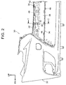
- projected portions 42 are integrally formed in the opposite wall 36 (see shaded portions in FIG. 3 ).
- the projected portion 42 is projected to the vehicle rear side (to the chamber member 20 side) from a general surface 36A of the opposite wall 36 and is disposed to face the front surface 20A of the chamber member 20. Accordingly, the gap G2 at the center of the bumper cover 30 in the vehicle width direction is configured to be filled by the projected portion 42.
- the projected portion 42 is formed in a substantially rectangular shape when seen from the vehicle rear side, and a lower side portion of the projected portion 42 is formed in a concave-convex shape when seen from the vehicle front side. Furthermore, plural (two in the embodiment) dents 44 that are opened to the vehicle rear side are formed in the projected portion 42, and each of the dents 44 is formed in a substantially rectangular shape when seen from the vehicle rear side and is aligned in the vehicle width direction. A bottom surface 44A of the dent 44 is formed on the same plane as the general surface 36A (see FIG. 1 ).
- the projected portions 42 are formed in plural while having a space therebetween in the vehicle width direction.
- a concave portion 46 that is opened to the vehicle rear side is formed between the projected portions 42 that are adjacent to each other in the vehicle width direction, and the opposite wall 36 is formed in the concave-convex shape in the plan view.
- the concave portion 46 is disposed on the vehicle rear side than the general surface 36A of the opposite wall 36.
- a portion of the bumper cover 30 on the vehicle front side of the center wall 34 is assembled with an extension 48 that constitutes a design of the vehicle. Accordingly, the center wall 34 is covered with the extension 48 from the vehicle front side.
- the absorber 28 is provided on the vehicle lower side of the chamber member 20, and the bumper cover 30 is provided on the vehicle front side of the chamber member 20 and the absorber 28.
- the center wall 34 is formed at the center of the bumper cover 30 in the vehicle width direction, and the opposite wall 36 of the center wall 34 is disposed to face the front surface 20A of the chamber member 20.
- the opposite wall 36 of the bumper cover 30 is integrally formed with the projected portion 42, and the projected portion 42 is projected from the opposite wall 36 to the chamber member 20 side (vehicle rear side).
- the front bumper 12 it is configured in the front bumper 12 that the absorber 28 is not interposed between the bumper cover 30 and the chamber member 20, that the gap G2 between the bumper cover 30 and the chamber member 20 is filled by the projected portion 42, and that the projected portion 42 presses the front surface 20A of the chamber member 20. Accordingly, the front bumper 12 can adopt a structure that is less likely to be affected by the temperature.
- the chamber member 20 and the main body 32 of the bumper cover 30 are disposed to face each other in corner portions of the vehicle (both ends of the bumper cover 30 in the vehicle width direction), the chamber member 20 can be pressed by the main body 32. Accordingly, in a portion of the front bumper 12 where the dimension of the gap G2 in the vehicle front-rear direction is relatively small, the chamber member 20 can be pressed by the main body 32 without using the absorber 28 that is difficult to be formed in a specified thickness or less.
- the lower side wall 38 of the bumper cover 30 that faces the absorber 28 is disposed on the vehicle front side than the opposite wall 36, and the lower end of the opposite wall 36 and the upper end of the lower side wall 38 are connected in the stepped shape in the side view. Moreover, the plural projected portions 42 are provided with the space therebetween in the vehicle width direction. Accordingly, it is possible to favorably determine whether what has collided with the vehicle is the pedestrian or the collision body other than the pedestrian (such as a road side marker or a post cone, for example).
- the pedestrian is collapsed on a hood of the vehicle in a collision of the vehicle with the pedestrian.
- a collision load to the rear and obliquely downward of the vehicle is mainly applied to the bumper cover 30 from the pedestrian (see an arrow F in FIG. 1 ).
- the opposite wall 36 is bent and deformed (tilted) to the rear and obliquely downward of the vehicle with the lower end of the opposite wall 36 as a fulcrum, and then the chamber member 20 is pressed by the opposite wall 36 (see a two-dot chain line in FIG. 1 ).
- the collision body enters the bumper cover 30 in a substantially horizontal manner.
- the collision load to the vehicle rear side is mainly applied to the bumper cover 30.
- the opposite wall 36 and the lower side wall 38 are connected in the stepped shape in the side view, the opposite wall 36 and the lower side wall 38 are prevented from being bent and deformed to the vehicle rear side by the portion that is formed in the stepped shape. Consequently, compared to a deformation amount of the chamber member 20 in the collision of the vehicle with the pedestrian, the deformation amount of the chamber member 20 becomes small in the collision of the vehicle with the collision body other than the pedestrian. In other words, a large difference is caused between the deformation amount of the chamber member 20 in the collision of the vehicle with the pedestrian and the deformation amount of the chamber member 20 in the collision of the vehicle with the collision body other than the pedestrian.
- the projected portions 42 are provided in plural with the space therebetween in the vehicle width direction. That is, the opposite wall 36 is formed in the concave-convex shape in the plan view. Thus, bending rigidity of the opposite wall 36 in the vehicle front-rear direction in the plan view is prevented from becoming excessively high. Accordingly, in the collision of the vehicle with the pedestrian, for example, the opposite wall 36 is bent and deformed to the chamber member 20 side in an appropriate manner, and the chamber member 20 is pressed and deformed by the opposite wall 36. Therefore, it is possible to favorably determine whether the vehicle collides with the pedestrian or the collision body other than the pedestrian.
- the extension 48 is provided on the vehicle front side of the projected portion 42 in the bumper cover 30. Accordingly, the projected portion 42 is prevented from being exposed to the outside by the extension 48. Therefore, even when the projected portion 42 is provided in the bumper cover 30, it is possible to prevent degradation of the vehicle design.
- the concave portion 46 of the center wall 34 is provided on the vehicle rear side than the general surface 36A of the opposite wall 36.
- the concave portion 46 may be provided on the same plane as the general surface 36A or may be provided on the vehicle front side than the general surface 36A.
- the projected portions 42 are aligned in a row in the vehicle width direction.
- a length of the projected portion 42 may be set to be short in a vehicle up-down direction.
- the projected portions may be arranged in a plurality of rows, each of the rows may have a plurality of the projected portions arranged in the vehicle width direction and the rows may be arranged in a vehicle up-down direction.
- the projected portion 42 is formed in the substantially rectangular shape when seen from the vehicle rear side, and the lower side portion of the projected portion 42 is formed in the concave-convex shape when seen from the vehicle front side.
- the projected portion 42 is not limited to this shape.
- the projected portion 42 may be formed in the substantially rectangular shape when seen from the vehicle rear side, and the lower side portion of the projected portion 42 may be formed to be linear.
- the dents 44 may be set to align in the vehicle up-down direction and the vehicle width direction.
- the length of the center wall 34 in the vehicle width direction and the length of the gap G2 in the vehicle front-rear direction of this embodiment can be set in any length.
- the length of the center wall 34 in the vehicle width direction and the length of the gap G2 in the vehicle front-rear direction can appropriately be set according to various types of vehicles.
- the collision determination system 10 is applied to the front bumper 12.
- the present invention is not limited to this.
- the above structure may be inverted longitudinally, and the collision determination system 10 may be applied to a rear bumper.
Landscapes
- Engineering & Computer Science (AREA)
- Mechanical Engineering (AREA)
- Body Structure For Vehicles (AREA)
- Force Measurement Appropriate To Specific Purposes (AREA)
Claims (9)
- Pare-chocs de véhicule comprenant un appareil de détection de collision avec un piéton, caractérisé en ce qu'il comprend :un renforcement de pare-chocs (14) qui est disposé dans le sens de la largeur du véhicule en tant que direction longitudinale de ce dernier ;un élément de chambre (20) qui est disposé dans le sens de la largeur du véhicule en tant que direction longitudinale de ce dernier et est adjacent à une surface latérale externe du renforcement de pare-chocs dans une direction avant-arrière du véhicule, à l'intérieur de l'élément de chambre fonctionnant comme une chambre de pression (22) ;un détecteur de pression (24) qui émet un signal correspondant à un changement de pression de la chambre de pression ;une unité de détermination de collision (26) qui détermine si un véhicule a heurté un piéton ou pas par le signal émis par le détecteur de pression ;un amortisseur (28) qui est prévu sur un côté inférieur de véhicule de l'élément de chambre, est adjacent à la surface latérale externe du renforcement de pare-chocs dans la direction avant-arrière du véhicule, et est disposé dans le sens de la largeur du véhicule en tant que direction longitudinale de ce dernier ; etun couvercle de pare-chocs (30) qui est prévu sur l'extérieur de l'élément de chambre et l'amortisseur dans la direction avant-arrière du véhicule et comprend une partie en saillie (42) qui fait saillie d'une paroi opposée (36) qui fait face à l'élément de chambre jusqu'au côté de l'élément de chambre,dans lequel le couvercle de pare-chocs a une pluralité de parties en saillie (42) agencées à intervalles dans le sens de la largeur du véhicule.
- Pare-chocs de véhicule selon la revendication 1,
dans lequel le couvercle de pare-chocs comprend une paroi latérale inférieure qui est disposée sur un côté inférieur du véhicule de la paroi opposée et sur l'extérieur de la paroi opposée dans la direction avant-arrière du véhicule, une extrémité inférieure de la paroi opposée et une extrémité supérieure de la paroi latérale inférieure sont raccordées selon une forme étagée. - Pare-chocs de véhicule selon la revendication 2, dans lequel :les parties en saillie sont agencées dans une pluralité de rangées ;chacune de la pluralité de rangées a une pluralité de parties en saillie agencées dans le sens de la largeur du véhicule ; etla pluralité de rangées sont agencées dans la direction de haut en bas du véhicule.
- Pare-chocs de véhicule selon la revendication 1, dans lequel
le couvercle de pare-chocs comprend une paroi centrale au niveau d'un centre du couvercle de pare-chocs dans le sens de la largeur du véhicule et un corps principal,
le corps principal est formé sensiblement selon une forme de U qui est ouvert vers un côté supérieur de véhicule sur une vue de face,
la paroi centrale est disposée pour faire face à l'élément de chambre et à l'amortisseur, et
la paroi centrale est formée pour être une plaque sensiblement longue, s'étend entre les deux extrémités du corps principal dans le sens de la largeur du véhicule, et est disposée dans le sens de la largeur du véhicule en tant que direction longitudinale de ce dernier. - Pare-chocs de véhicule selon la revendication 1, dans lequel
la partie en saillie est formée selon une forme sensiblement rectangulaire lorsqu'elle est observée à partir d'un côté arrière du véhicule,
une partie latérale inférieure de la partie en saillie est formée selon une forme concavo-convexe, lorsqu'elle est observée à partir du côté avant du véhicule, plusieurs bosses qui sont ouvertes vers le côté arrière du véhicule étant en outre formées dans la partie en saillie, et
chacune des bosses est formée selon des formes sensiblement rectangulaires lorsqu'elles sont observées à partir du côté arrière du véhicule, et les bosses sont alignées dans le sens de la largeur du véhicule. - Pare-chocs de véhicule selon la revendication 1, dans lequel une extension qui constitue une conception du véhicule est prévue sur un côté externe de la partie en saillie dans les couvercles de pare-chocs dans la direction avant-arrière du véhicule.
- Pare-chocs de véhicule selon la revendication 2, dans lequel plusieurs bosses qui sont ouvertes vers un côté arrière de véhicule étant en outre formées dans la partie en saillie et les bosses font saillie à partir de la paroi opposée vers l'extérieur dans la direction avant-arrière du véhicule.
- Pare-chocs de véhicule selon la revendication 5, dans lequel les bosses font saillie du côté de paroi opposée vers l'extérieur dans la direction avant-arrière du véhicule.
- Pare-chocs de véhicule selon la revendication 6, dans lequel plusieurs bosses qui sont ouvertes vers le côté arrière du véhicule étant en outre formées dans la partie en saillie, et les bosses font saillie du côté de la paroi opposée jusqu'à l'extension.
Applications Claiming Priority (2)
| Application Number | Priority Date | Filing Date | Title |
|---|---|---|---|
| JP2013001825A JP5920228B2 (ja) | 2013-01-09 | 2013-01-09 | 歩行者衝突検出装置を備えた車両用バンパ |
| PCT/IB2013/002713 WO2014108723A1 (fr) | 2013-01-09 | 2013-12-10 | Pare-choc de véhicule comprenant un appareil de détection de collision avec un piéton |
Publications (2)
| Publication Number | Publication Date |
|---|---|
| EP2895357A1 EP2895357A1 (fr) | 2015-07-22 |
| EP2895357B1 true EP2895357B1 (fr) | 2016-05-04 |
Family
ID=50002780
Family Applications (1)
| Application Number | Title | Priority Date | Filing Date |
|---|---|---|---|
| EP13824335.7A Not-in-force EP2895357B1 (fr) | 2013-01-09 | 2013-12-10 | Pare-choc de véhicule comprenant un appareil de détection de collision avec un piéton |
Country Status (5)
| Country | Link |
|---|---|
| US (1) | US9352715B2 (fr) |
| EP (1) | EP2895357B1 (fr) |
| JP (1) | JP5920228B2 (fr) |
| CN (1) | CN104736395A (fr) |
| WO (1) | WO2014108723A1 (fr) |
Families Citing this family (11)
| Publication number | Priority date | Publication date | Assignee | Title |
|---|---|---|---|---|
| CN103287381B (zh) * | 2013-06-18 | 2016-01-20 | 延锋彼欧汽车外饰系统有限公司 | 一种汽车的吸能装置 |
| DE102014010722A1 (de) * | 2014-07-19 | 2016-01-21 | Daimler Ag | Erfassungseinrichtung für einen Kraftwagenbug eines Personenkraftwagens |
| JP6079712B2 (ja) | 2014-07-24 | 2017-02-15 | トヨタ自動車株式会社 | 車両用バンパ |
| JP6311685B2 (ja) * | 2015-09-29 | 2018-04-18 | トヨタ自動車株式会社 | 車両用センサの取り付け構造 |
| JP6285977B2 (ja) * | 2016-03-28 | 2018-02-28 | 本田技研工業株式会社 | 車両用バンパ |
| US10137850B2 (en) * | 2017-01-11 | 2018-11-27 | Toyota Motor Engineering & Manufacturing North America, Inc. | Vehicle bumper collision indicator |
| JP6863209B2 (ja) * | 2017-09-29 | 2021-04-21 | トヨタ自動車株式会社 | センサ用プロテクタ及びこれを備えた車両 |
| US10259412B1 (en) * | 2017-12-08 | 2019-04-16 | GM Global Technology Operations LLC | Bumper collision sensor for an automotive vehicle |
| CN108819887B (zh) * | 2018-04-25 | 2020-05-19 | 东风汽车有限公司 | 汽车前端吸能块 |
| JP7102644B2 (ja) * | 2018-04-25 | 2022-07-20 | ダイハツ工業株式会社 | バンパ構造 |
| US12187212B2 (en) * | 2020-11-11 | 2025-01-07 | Hyundai Mobis Co., Ltd. | System method for determining collision of walker |
Family Cites Families (14)
| Publication number | Priority date | Publication date | Assignee | Title |
|---|---|---|---|---|
| FR2777615B1 (fr) * | 1998-04-15 | 2000-12-29 | Plastic Omnium Cie | Absorbeur de chocs a section ondulee et pare-chocs muni d'un tel absorbeur de chocs |
| US6863322B2 (en) * | 2000-05-31 | 2005-03-08 | Frederick D. Hunter | Motor vehicle bumper |
| JP4082692B2 (ja) * | 2004-03-18 | 2008-04-30 | 株式会社デンソー | 歩行者検知装置 |
| JP4210942B2 (ja) * | 2005-02-23 | 2009-01-21 | 株式会社デンソー | 車両用衝突物体判別装置 |
| JP4403518B2 (ja) * | 2007-07-13 | 2010-01-27 | 株式会社デンソー | 車両用衝突検知装置 |
| JP4688849B2 (ja) * | 2007-07-17 | 2011-05-25 | 株式会社デンソー | 衝突検出装置 |
| EP2023108B1 (fr) * | 2007-08-08 | 2011-08-31 | Honda Motor Co., Ltd. | Ensemble de capteur de charge piézoélectrique |
| JP4997017B2 (ja) * | 2007-08-08 | 2012-08-08 | 本田技研工業株式会社 | 車両用センサ組立体 |
| JP5104347B2 (ja) * | 2008-01-30 | 2012-12-19 | 株式会社デンソー | 歩行者衝突検知装置 |
| JP4883370B2 (ja) * | 2008-03-18 | 2012-02-22 | 株式会社デンソー | 車両用衝突検知装置 |
| JP5302643B2 (ja) | 2008-12-02 | 2013-10-02 | 株式会社デンソー | 衝突検出装置及び衝突検出方法 |
| JP4924629B2 (ja) | 2009-02-03 | 2012-04-25 | 株式会社デンソー | 車両用衝突検知装置 |
| JP5509863B2 (ja) * | 2010-01-14 | 2014-06-04 | トヨタ自動車株式会社 | 歩行者衝突検出装置 |
| DE102011000501B4 (de) * | 2011-02-04 | 2022-03-24 | Dr. Ing. H.C. F. Porsche Aktiengesellschaft | Sichtschutzblende für eine Sensoreinheit eines Kraftfahrzeugs |
-
2013
- 2013-01-09 JP JP2013001825A patent/JP5920228B2/ja active Active
- 2013-12-10 WO PCT/IB2013/002713 patent/WO2014108723A1/fr not_active Ceased
- 2013-12-10 EP EP13824335.7A patent/EP2895357B1/fr not_active Not-in-force
- 2013-12-10 CN CN201380055322.XA patent/CN104736395A/zh active Pending
- 2013-12-10 US US14/435,348 patent/US9352715B2/en not_active Expired - Fee Related
Also Published As
| Publication number | Publication date |
|---|---|
| EP2895357A1 (fr) | 2015-07-22 |
| JP5920228B2 (ja) | 2016-05-18 |
| US9352715B2 (en) | 2016-05-31 |
| US20150274109A1 (en) | 2015-10-01 |
| JP2014133452A (ja) | 2014-07-24 |
| WO2014108723A1 (fr) | 2014-07-17 |
| CN104736395A (zh) | 2015-06-24 |
Similar Documents
| Publication | Publication Date | Title |
|---|---|---|
| US9352715B2 (en) | Vehicle bumper including pedestrian collision detection apparatus | |
| US9718423B2 (en) | Vehicle bumper structure including a pedestrian collision detection sensor | |
| US8350685B2 (en) | Collision detecting device | |
| EP2559597B1 (fr) | Dispositif de détection de collision de piétons | |
| US9663053B2 (en) | Collision detection device for vehicle | |
| JP4466690B2 (ja) | 衝突検出装置 | |
| JP5509863B2 (ja) | 歩行者衝突検出装置 | |
| JP5962435B2 (ja) | 歩行者衝突検出装置を備えた車両用バンパ | |
| CN107235026B (zh) | 车辆用保险杠 | |
| US11052846B2 (en) | Vehicle bumper | |
| JP2009023405A (ja) | 衝突検知センサ | |
| JP5983558B2 (ja) | 歩行者衝突検出装置を備えた車両用バンパ構造 | |
| JP2016165977A (ja) | 衝突検出装置 | |
| JP2017007368A (ja) | 歩行者衝突検知センサを備えた車両用バンパ構造 | |
| JP2014104805A (ja) | 歩行者衝突検出装置を備えた車両用バンパ | |
| JP6314714B2 (ja) | 歩行者衝突検知センサを備えた車両用バンパ構造 | |
| JP4293023B2 (ja) | 車体前部構造 | |
| JP2000264142A (ja) | 車両用バンパ構造 | |
| JP4797897B2 (ja) | 車両用衝突検知装置 | |
| JP5994666B2 (ja) | 歩行者衝突検出装置を備えた車両用バンパ | |
| JP5895795B2 (ja) | 歩行者衝突検出装置を備えた車両用バンパ | |
| JP2015003620A (ja) | 歩行者衝突検出装置を備えた車両用バンパ |
Legal Events
| Date | Code | Title | Description |
|---|---|---|---|
| PUAI | Public reference made under article 153(3) epc to a published international application that has entered the european phase |
Free format text: ORIGINAL CODE: 0009012 |
|
| 17P | Request for examination filed |
Effective date: 20150415 |
|
| AK | Designated contracting states |
Kind code of ref document: A1 Designated state(s): AL AT BE BG CH CY CZ DE DK EE ES FI FR GB GR HR HU IE IS IT LI LT LU LV MC MK MT NL NO PL PT RO RS SE SI SK SM TR |
|
| AX | Request for extension of the european patent |
Extension state: BA ME |
|
| REG | Reference to a national code |
Ref country code: DE Ref legal event code: R079 Ref document number: 602013007363 Country of ref document: DE Free format text: PREVIOUS MAIN CLASS: B60R0021013600 Ipc: B60R0019180000 |
|
| GRAP | Despatch of communication of intention to grant a patent |
Free format text: ORIGINAL CODE: EPIDOSNIGR1 |
|
| RIC1 | Information provided on ipc code assigned before grant |
Ipc: B60R 19/18 20060101AFI20151116BHEP Ipc: B60R 21/0136 20060101ALI20151116BHEP Ipc: B60R 19/48 20060101ALI20151116BHEP |
|
| DAX | Request for extension of the european patent (deleted) | ||
| INTG | Intention to grant announced |
Effective date: 20151203 |
|
| GRAS | Grant fee paid |
Free format text: ORIGINAL CODE: EPIDOSNIGR3 |
|
| GRAA | (expected) grant |
Free format text: ORIGINAL CODE: 0009210 |
|
| AK | Designated contracting states |
Kind code of ref document: B1 Designated state(s): AL AT BE BG CH CY CZ DE DK EE ES FI FR GB GR HR HU IE IS IT LI LT LU LV MC MK MT NL NO PL PT RO RS SE SI SK SM TR |
|
| REG | Reference to a national code |
Ref country code: GB Ref legal event code: FG4D |
|
| REG | Reference to a national code |
Ref country code: CH Ref legal event code: EP |
|
| REG | Reference to a national code |
Ref country code: AT Ref legal event code: REF Ref document number: 796604 Country of ref document: AT Kind code of ref document: T Effective date: 20160515 |
|
| REG | Reference to a national code |
Ref country code: IE Ref legal event code: FG4D |
|
| REG | Reference to a national code |
Ref country code: DE Ref legal event code: R096 Ref document number: 602013007363 Country of ref document: DE |
|
| REG | Reference to a national code |
Ref country code: NL Ref legal event code: MP Effective date: 20160504 |
|
| REG | Reference to a national code |
Ref country code: LT Ref legal event code: MG4D |
|
| REG | Reference to a national code |
Ref country code: DE Ref legal event code: R084 Ref document number: 602013007363 Country of ref document: DE |
|
| REG | Reference to a national code |
Ref country code: GB Ref legal event code: 746 Effective date: 20160929 |
|
| PG25 | Lapsed in a contracting state [announced via postgrant information from national office to epo] |
Ref country code: LT Free format text: LAPSE BECAUSE OF FAILURE TO SUBMIT A TRANSLATION OF THE DESCRIPTION OR TO PAY THE FEE WITHIN THE PRESCRIBED TIME-LIMIT Effective date: 20160504 Ref country code: NO Free format text: LAPSE BECAUSE OF FAILURE TO SUBMIT A TRANSLATION OF THE DESCRIPTION OR TO PAY THE FEE WITHIN THE PRESCRIBED TIME-LIMIT Effective date: 20160804 Ref country code: NL Free format text: LAPSE BECAUSE OF FAILURE TO SUBMIT A TRANSLATION OF THE DESCRIPTION OR TO PAY THE FEE WITHIN THE PRESCRIBED TIME-LIMIT Effective date: 20160504 Ref country code: FI Free format text: LAPSE BECAUSE OF FAILURE TO SUBMIT A TRANSLATION OF THE DESCRIPTION OR TO PAY THE FEE WITHIN THE PRESCRIBED TIME-LIMIT Effective date: 20160504 |
|
| REG | Reference to a national code |
Ref country code: FR Ref legal event code: PLFP Year of fee payment: 4 |
|
| REG | Reference to a national code |
Ref country code: AT Ref legal event code: MK05 Ref document number: 796604 Country of ref document: AT Kind code of ref document: T Effective date: 20160504 |
|
| PG25 | Lapsed in a contracting state [announced via postgrant information from national office to epo] |
Ref country code: GR Free format text: LAPSE BECAUSE OF FAILURE TO SUBMIT A TRANSLATION OF THE DESCRIPTION OR TO PAY THE FEE WITHIN THE PRESCRIBED TIME-LIMIT Effective date: 20160805 Ref country code: RS Free format text: LAPSE BECAUSE OF FAILURE TO SUBMIT A TRANSLATION OF THE DESCRIPTION OR TO PAY THE FEE WITHIN THE PRESCRIBED TIME-LIMIT Effective date: 20160504 Ref country code: HR Free format text: LAPSE BECAUSE OF FAILURE TO SUBMIT A TRANSLATION OF THE DESCRIPTION OR TO PAY THE FEE WITHIN THE PRESCRIBED TIME-LIMIT Effective date: 20160504 Ref country code: SE Free format text: LAPSE BECAUSE OF FAILURE TO SUBMIT A TRANSLATION OF THE DESCRIPTION OR TO PAY THE FEE WITHIN THE PRESCRIBED TIME-LIMIT Effective date: 20160504 Ref country code: ES Free format text: LAPSE BECAUSE OF FAILURE TO SUBMIT A TRANSLATION OF THE DESCRIPTION OR TO PAY THE FEE WITHIN THE PRESCRIBED TIME-LIMIT Effective date: 20160504 Ref country code: PT Free format text: LAPSE BECAUSE OF FAILURE TO SUBMIT A TRANSLATION OF THE DESCRIPTION OR TO PAY THE FEE WITHIN THE PRESCRIBED TIME-LIMIT Effective date: 20160905 Ref country code: LV Free format text: LAPSE BECAUSE OF FAILURE TO SUBMIT A TRANSLATION OF THE DESCRIPTION OR TO PAY THE FEE WITHIN THE PRESCRIBED TIME-LIMIT Effective date: 20160504 |
|
| PG25 | Lapsed in a contracting state [announced via postgrant information from national office to epo] |
Ref country code: IT Free format text: LAPSE BECAUSE OF FAILURE TO SUBMIT A TRANSLATION OF THE DESCRIPTION OR TO PAY THE FEE WITHIN THE PRESCRIBED TIME-LIMIT Effective date: 20160504 |
|
| PG25 | Lapsed in a contracting state [announced via postgrant information from national office to epo] |
Ref country code: DK Free format text: LAPSE BECAUSE OF FAILURE TO SUBMIT A TRANSLATION OF THE DESCRIPTION OR TO PAY THE FEE WITHIN THE PRESCRIBED TIME-LIMIT Effective date: 20160504 Ref country code: SK Free format text: LAPSE BECAUSE OF FAILURE TO SUBMIT A TRANSLATION OF THE DESCRIPTION OR TO PAY THE FEE WITHIN THE PRESCRIBED TIME-LIMIT Effective date: 20160504 Ref country code: EE Free format text: LAPSE BECAUSE OF FAILURE TO SUBMIT A TRANSLATION OF THE DESCRIPTION OR TO PAY THE FEE WITHIN THE PRESCRIBED TIME-LIMIT Effective date: 20160504 Ref country code: CZ Free format text: LAPSE BECAUSE OF FAILURE TO SUBMIT A TRANSLATION OF THE DESCRIPTION OR TO PAY THE FEE WITHIN THE PRESCRIBED TIME-LIMIT Effective date: 20160504 Ref country code: RO Free format text: LAPSE BECAUSE OF FAILURE TO SUBMIT A TRANSLATION OF THE DESCRIPTION OR TO PAY THE FEE WITHIN THE PRESCRIBED TIME-LIMIT Effective date: 20160504 |
|
| REG | Reference to a national code |
Ref country code: DE Ref legal event code: R097 Ref document number: 602013007363 Country of ref document: DE |
|
| PG25 | Lapsed in a contracting state [announced via postgrant information from national office to epo] |
Ref country code: AT Free format text: LAPSE BECAUSE OF FAILURE TO SUBMIT A TRANSLATION OF THE DESCRIPTION OR TO PAY THE FEE WITHIN THE PRESCRIBED TIME-LIMIT Effective date: 20160504 Ref country code: BE Free format text: LAPSE BECAUSE OF FAILURE TO SUBMIT A TRANSLATION OF THE DESCRIPTION OR TO PAY THE FEE WITHIN THE PRESCRIBED TIME-LIMIT Effective date: 20160504 Ref country code: PL Free format text: LAPSE BECAUSE OF FAILURE TO SUBMIT A TRANSLATION OF THE DESCRIPTION OR TO PAY THE FEE WITHIN THE PRESCRIBED TIME-LIMIT Effective date: 20160504 Ref country code: SM Free format text: LAPSE BECAUSE OF FAILURE TO SUBMIT A TRANSLATION OF THE DESCRIPTION OR TO PAY THE FEE WITHIN THE PRESCRIBED TIME-LIMIT Effective date: 20160504 |
|
| PLBE | No opposition filed within time limit |
Free format text: ORIGINAL CODE: 0009261 |
|
| STAA | Information on the status of an ep patent application or granted ep patent |
Free format text: STATUS: NO OPPOSITION FILED WITHIN TIME LIMIT |
|
| 26N | No opposition filed |
Effective date: 20170207 |
|
| PG25 | Lapsed in a contracting state [announced via postgrant information from national office to epo] |
Ref country code: SI Free format text: LAPSE BECAUSE OF FAILURE TO SUBMIT A TRANSLATION OF THE DESCRIPTION OR TO PAY THE FEE WITHIN THE PRESCRIBED TIME-LIMIT Effective date: 20160504 |
|
| PG25 | Lapsed in a contracting state [announced via postgrant information from national office to epo] |
Ref country code: MC Free format text: LAPSE BECAUSE OF FAILURE TO SUBMIT A TRANSLATION OF THE DESCRIPTION OR TO PAY THE FEE WITHIN THE PRESCRIBED TIME-LIMIT Effective date: 20160504 |
|
| REG | Reference to a national code |
Ref country code: CH Ref legal event code: PL |
|
| REG | Reference to a national code |
Ref country code: IE Ref legal event code: MM4A |
|
| PG25 | Lapsed in a contracting state [announced via postgrant information from national office to epo] |
Ref country code: LU Free format text: LAPSE BECAUSE OF NON-PAYMENT OF DUE FEES Effective date: 20161210 Ref country code: LI Free format text: LAPSE BECAUSE OF NON-PAYMENT OF DUE FEES Effective date: 20161231 Ref country code: CH Free format text: LAPSE BECAUSE OF NON-PAYMENT OF DUE FEES Effective date: 20161231 |
|
| REG | Reference to a national code |
Ref country code: FR Ref legal event code: PLFP Year of fee payment: 5 |
|
| PG25 | Lapsed in a contracting state [announced via postgrant information from national office to epo] |
Ref country code: IE Free format text: LAPSE BECAUSE OF NON-PAYMENT OF DUE FEES Effective date: 20161210 |
|
| PG25 | Lapsed in a contracting state [announced via postgrant information from national office to epo] |
Ref country code: HU Free format text: LAPSE BECAUSE OF FAILURE TO SUBMIT A TRANSLATION OF THE DESCRIPTION OR TO PAY THE FEE WITHIN THE PRESCRIBED TIME-LIMIT; INVALID AB INITIO Effective date: 20131210 |
|
| PG25 | Lapsed in a contracting state [announced via postgrant information from national office to epo] |
Ref country code: IS Free format text: LAPSE BECAUSE OF FAILURE TO SUBMIT A TRANSLATION OF THE DESCRIPTION OR TO PAY THE FEE WITHIN THE PRESCRIBED TIME-LIMIT Effective date: 20160504 Ref country code: MK Free format text: LAPSE BECAUSE OF FAILURE TO SUBMIT A TRANSLATION OF THE DESCRIPTION OR TO PAY THE FEE WITHIN THE PRESCRIBED TIME-LIMIT Effective date: 20160504 Ref country code: CY Free format text: LAPSE BECAUSE OF FAILURE TO SUBMIT A TRANSLATION OF THE DESCRIPTION OR TO PAY THE FEE WITHIN THE PRESCRIBED TIME-LIMIT Effective date: 20160504 |
|
| PG25 | Lapsed in a contracting state [announced via postgrant information from national office to epo] |
Ref country code: BG Free format text: LAPSE BECAUSE OF FAILURE TO SUBMIT A TRANSLATION OF THE DESCRIPTION OR TO PAY THE FEE WITHIN THE PRESCRIBED TIME-LIMIT Effective date: 20160504 |
|
| PG25 | Lapsed in a contracting state [announced via postgrant information from national office to epo] |
Ref country code: MT Free format text: LAPSE BECAUSE OF NON-PAYMENT OF DUE FEES Effective date: 20161210 |
|
| PG25 | Lapsed in a contracting state [announced via postgrant information from national office to epo] |
Ref country code: AL Free format text: LAPSE BECAUSE OF FAILURE TO SUBMIT A TRANSLATION OF THE DESCRIPTION OR TO PAY THE FEE WITHIN THE PRESCRIBED TIME-LIMIT Effective date: 20160504 Ref country code: TR Free format text: LAPSE BECAUSE OF FAILURE TO SUBMIT A TRANSLATION OF THE DESCRIPTION OR TO PAY THE FEE WITHIN THE PRESCRIBED TIME-LIMIT Effective date: 20160504 |
|
| PGFP | Annual fee paid to national office [announced via postgrant information from national office to epo] |
Ref country code: FR Payment date: 20211109 Year of fee payment: 9 Ref country code: DE Payment date: 20211102 Year of fee payment: 9 Ref country code: GB Payment date: 20211028 Year of fee payment: 9 |
|
| REG | Reference to a national code |
Ref country code: DE Ref legal event code: R119 Ref document number: 602013007363 Country of ref document: DE |
|
| GBPC | Gb: european patent ceased through non-payment of renewal fee |
Effective date: 20221210 |
|
| PG25 | Lapsed in a contracting state [announced via postgrant information from national office to epo] |
Ref country code: GB Free format text: LAPSE BECAUSE OF NON-PAYMENT OF DUE FEES Effective date: 20221210 Ref country code: DE Free format text: LAPSE BECAUSE OF NON-PAYMENT OF DUE FEES Effective date: 20230701 |
|
| PG25 | Lapsed in a contracting state [announced via postgrant information from national office to epo] |
Ref country code: FR Free format text: LAPSE BECAUSE OF NON-PAYMENT OF DUE FEES Effective date: 20221231 |