EP2896114B1 - Rotor einer elektrischen rotationsmaschine mit einem läuferkörper mit aussparungen - Google Patents
Rotor einer elektrischen rotationsmaschine mit einem läuferkörper mit aussparungen Download PDFInfo
- Publication number
- EP2896114B1 EP2896114B1 EP13795859.1A EP13795859A EP2896114B1 EP 2896114 B1 EP2896114 B1 EP 2896114B1 EP 13795859 A EP13795859 A EP 13795859A EP 2896114 B1 EP2896114 B1 EP 2896114B1
- Authority
- EP
- European Patent Office
- Prior art keywords
- rotor
- pole
- recesses
- axis
- bridges
- Prior art date
- Legal status (The legal status is an assumption and is not a legal conclusion. Google has not performed a legal analysis and makes no representation as to the accuracy of the status listed.)
- Active
Links
Images



Classifications
-
- H—ELECTRICITY
- H02—GENERATION; CONVERSION OR DISTRIBUTION OF ELECTRIC POWER
- H02K—DYNAMO-ELECTRIC MACHINES
- H02K1/00—Details of the magnetic circuit
- H02K1/06—Details of the magnetic circuit characterised by the shape, form or construction
- H02K1/22—Rotating parts of the magnetic circuit
- H02K1/27—Rotor cores with permanent magnets
- H02K1/2706—Inner rotors
- H02K1/272—Inner rotors the magnetisation axis of the magnets being perpendicular to the rotor axis
- H02K1/274—Inner rotors the magnetisation axis of the magnets being perpendicular to the rotor axis the rotor consisting of two or more circumferentially positioned magnets
- H02K1/2753—Inner rotors the magnetisation axis of the magnets being perpendicular to the rotor axis the rotor consisting of two or more circumferentially positioned magnets the rotor consisting of magnets or groups of magnets arranged with alternating polarity
- H02K1/276—Magnets embedded in the magnetic core, e.g. interior permanent magnets [IPM]
- H02K1/2766—Magnets embedded in the magnetic core, e.g. interior permanent magnets [IPM] having a flux concentration effect
-
- H—ELECTRICITY
- H02—GENERATION; CONVERSION OR DISTRIBUTION OF ELECTRIC POWER
- H02K—DYNAMO-ELECTRIC MACHINES
- H02K2213/00—Specific aspects, not otherwise provided for and not covered by codes H02K2201/00 - H02K2211/00
- H02K2213/03—Machines characterised by numerical values, ranges, mathematical expressions or similar information
Definitions
- the present invention relates to rotating electrical machines and in particular those comprising a flux-concentration rotor, and more particularly the rotors of such machines.
- Rotating electrical machines comprising a rotor which includes magnets arranged in housings so as to define poles of the rotor.
- the housings can be in the form of a circular arc or V. They are separated from the air gap by circumferentially oriented material bridges, which maintain the cohesion of the rotor against the mechanical stresses that the machine undergoes.
- Such machines are known for example by EP 0746079 , US 6,121,706 , US 6,630,762 , US 7,779,153 as well as by the requests EP 1 763 121 , US 2002/0175584 and WO 2008/123086 .
- the demand EP 1 276 204 is directed to a permanent magnet motor in which the permanent magnets are arranged in a single row.
- a rotary electric machine rotor comprising a rotor mass in which housings are arranged so as to define the rotor poles.
- each pole having a radial axis of the pole, the housings being of elongate shape and each having two short sides, the housings being arranged in several rows per pole, a row comprising at least three housings arranged consecutively, their short sides defining between two consecutive housings of the same row a material bridge , this bridge of material extending generally along a longitudinal axis of the bridge oriented obliquely towards the radial axis of the corresponding pole of the rotor, when moving away from the axis of rotation.
- the rotor according to the invention makes it possible to reconcile the aforementioned contradictory requirements, that is to say on the one hand the circulation of the flux in the magnetic circuit, and on the other hand the mechanical strength of the rotor.
- the obliquely oriented material bridges mentioned above make it possible to withstand the centrifugal forces to which the rotor can be subjected, without penalizing the machine on the magnetic plane.
- the rotor may comprise permanent magnets inserted in all or part of the dwellings, for example in at least half of the dwellings, or even in more than two thirds of the dwellings, better still in all the dwellings.
- Permanent magnets can be made of ferrites or with rare earths or with any other type of magnetic material.
- the arrangement of the housings makes it possible to concentrate the flux of the magnets and to obtain with ferrite magnets interesting performances.
- the housings of the same row are arranged in a central branch and two lateral branches located on either side of the central branch, giving for example a U-shaped configuration, the central branch being for example alone to include one or more permanent magnets, the side branches not housing permanent magnet.
- the rotor may be devoid of permanent magnet. In this case it is a rotor of a reluctance machine.
- radial axis of the pole means an axis of the pole oriented radially, that is to say, according to a radius of the rotor. It can be an axis of symmetry for the pole. This radial axis can intersect the summit of the pole.
- the bridges of material formed between the housings may extend obliquely generally along a longitudinal axis of the bridge which can form with the radial axis of the corresponding pole of the rotor an angle of a non-zero value and greater than 5 °, better than 10 °, for example of the order of about 15 °.
- the angle may be less than 45 °, more preferably less than 30 °, or even less than 20 °.
- longitudinal axis of the bridge means the axis disposed centrally relative to the two short sides of the adjacent housing defining the bridge material. This axis is preferably rectilinear.
- the concavity of the row can be oriented towards the top of the pole, that is towards the gap.
- the housing of this pole are arranged in several rows, each concavity which can be oriented towards the top of the pole, especially in substantially concentric rows.
- concentric is meant that the middle axes of the rows of housing, taken in a plane perpendicular to the axis of rotation of the rotor, intersect at one point. This arrangement in several concentric rows makes it possible to improve the concentration of the flow without necessarily having to increase the size of the housings or the quantity of permanent magnets necessary to obtain an equivalent flux.
- the number of rows per pole can in particular be two, three or four.
- the rotor When the rotor has several rows for the same pole, the latter may be of decreasing length when moving towards the air gap, the longest being closer to the axis of rotation and the shorter one being closer to the axis of rotation. the air gap.
- the length of a row is the cumulative length of the dwellings in that row.
- At least two housings of two rows of the same pole can extend parallel to each other. All one-row dwellings may extend parallel to the corresponding dwellings of another row.
- the rotor may comprise as many obliquely oriented material bridges as rows of dwellings, or up to twice as much, or even three times more.
- Number of material bridges oriented obliquely in a pole may be equal to the number of housings in the pole, to which the number of rows in said pole is subtracted.
- a row has at least three dwellings.
- a row may for example comprise a central housing and two lateral housing. At least one row may comprise an odd number of dwellings, for example at least three dwellings.
- At least one pole comprises a row of housings having a lower number of housings than those of another row of this pole, for example two against three for the other row.
- the row with the smallest number of housings is preferably the closest to the gap and furthest from the axis of rotation.
- the arrangement of the housings and / or material bridges in a row is preferably symmetrical with respect to the radial axis of the pole.
- the housing can be arranged in V or U, the U may have a flared shape towards the air gap.
- the housing constituting the lateral branches of the U may be non-parallel to each other.
- the inclination of the radial bridges can be opposite to that of the lateral housings, with respect to the radial axis of the pole.
- the central housing may be longer or shorter than that of a branch of the U.
- the branches of the U are shorter that the central branch constituting the bottom of the U.
- the housings may each extend, when observed in section in a plane perpendicular to the axis of rotation of the rotor, along a longitudinal axis which may be rectilinear or curved.
- the housings can have a constant or variable width when moving along their longitudinal axis, in a plane perpendicular to the axis of rotation of the rotor.
- the short sides of a housing are oriented towards the radial axis of the pole when moving away from the axis of rotation, and converge for example substantially to the top of the pole.
- the housing may have, in cross section, that is to say perpendicular to the axis of rotation, a generally rectangular or trapezoidal shape, this list is not limiting.
- the short sides of a dwelling may be perpendicular to the long sides of the dwelling.
- the short sides of a housing can be inclined relative to the long sides of the housing.
- At least one dwelling may have two long sides, one of the long sides being smaller than the other.
- the shortest of the long sides may be located closer to the gap than the longest of the long sides.
- the short sides of a dwelling are straight.
- the material bridges between two consecutive housings of a row may have a width, measured perpendicular to their longitudinal axis, of less than 8 mm and the bridges of material may have a width greater than 0.5 mm.
- Permanent magnets may be of a generally rectangular shape. Given the shape of the housing, the establishment of magnets in the housing can leave a free space in the housing between the magnets and the short sides of the corresponding housing.
- the free space is for example of generally triangular shape.
- the longitudinal axes of two material bridges of two different rows of the same pole are parallel to each other.
- the distance d is measured perpendicular to said longitudinal axes. This distance d may be less than a multiple of the greatest width of the corresponding material bridges, for example less than three times, or even less than twice this greater width, or even less than this greater width. Such an offset makes it possible to compensate for the flexions introduced by the centrifugal forces.
- the subject of the invention is a rotary electric machine rotor comprising a rotor mass in which housings are arranged so as to define the poles of the rotor, each pole having a radial axis of the pole, the housings being of elongated shape and each having two short sides, the housings being arranged for each pole in several rows per pole, whose concavity can be oriented towards the air gap, a row comprising at least three housings disposed consecutively, their short sides defining between two consecutive dwellings of the same row a bridge of material, this bridge of material extending generally along a longitudinal axis of the bridge, the longitudinal axes of two bridges of material belonging to two different rows being parallel to each other and offset by a distance d between 0 (excluded value) and 10 mm.
- the longitudinal axes of these two bridges of material are not parallel to each other. They can form with the radial axis of the pole a varying angle, for example, which increases when one approaches the axis of rotation.
- the offset of the longitudinal axes of the bridges may be in this case to the radial axis of the pole when approaching the axis of rotation, ie the offset is on the opposite side of the radial axis of the pole when we are getting closer to the top of the pole.
- the offset of the longitudinal axes of the bridges may be alternatively to the radial axis of the pole when moving away from the axis of rotation, ie the offset is in the direction of the radial axis of the pole when the we are getting closer to the top of the pole.
- the offset may be smaller than the widest bridge width.
- the rotor mass may be formed of a stack of sheets or one or more individual sheet (s) wound (s) on it (s) itself (s) around the axis of rotation. Each sheet metal layer of the rotor mass can be in one piece.
- the rotor may be devoid of individual pole pieces.
- the rotor may comprise a number of poles of between 2 and 12, better still between 4 and 8.
- the invention further relates, in another of its aspects, to a rotating electrical machine comprising a rotor as described above.
- the machine can be reluctant. It can constitute a synchronous motor.
- the machine can operate at a nominal peripheral speed (tangential velocity taken at the outer diameter of the rotor) which may be greater than or equal to 100 meters per second, the machine according to the invention allowing operation at high speeds if desired.
- a nominal peripheral speed tangential velocity taken at the outer diameter of the rotor
- the machine can have a relatively large size.
- the diameter of the rotor may be greater than 50 mm, more preferably greater than 80 mm, being for example between 80 and 300 mm.
- FIG. 1 a rotor 1 of rotating electrical machine, comprising a rotor mass 2 in which are provided housing 3 so as to define the poles 4 of the rotor, each pole having a radial axis X.
- the rotor comprises nine housings per pole, which are arranged in three concentric rows 6 around each of the poles, the concavity of the rows being oriented towards the gap.
- a row 6 has three housings 3 arranged consecutively in the row.
- the three rows 6 of the same pole are of decreasing length when moving towards the gap, the longest being located on the side of the axis of rotation and the shortest side of the air gap.
- the housings 3 are of elongate shape, each extending along a longitudinal axis Y which forms an angle ⁇ with the radial axis X of the pole. They each comprise two small sides 9, the respective narrow sides 9 of two consecutive housings 3 of the same row 6 defining between them a bridge of material 10.
- the material bridge 10 extends generally along a longitudinal axis Z of the bridge oriented towards the radial axis X of the corresponding pole of the rotor 1 as one moves away from the axis of rotation.
- the longitudinal axis Z of the material bridge 10 is rectilinear and forms with the radial axis X of the corresponding pole of the rotor an angle ⁇ of a non-zero value and greater than 5 °, which in this example is of the order of about 15 °.
- the small sides 9 of a housing are oriented in the direction of the radial axis X of the pole as one moves towards the air gap.
- the housings 3 are generally trapezoidal in shape, and have two long sides 14, one of the long sides being smaller than the other, the shortest of the long sides being closer to the gap than the longest of the long sides .
- the rotor 1 has twice as many material bridges as rows of housings, each row 6 comprising three housings 3 and two bridges of material 10.
- the number of bridges of material 10 in a pole 4 is equal to the number of housings in the pole, which subtract the number of rows 6 in said pole.
- Each row 6 has a central housing 3a and two lateral housing 3b.
- the provision of Housing and bridges of material in a row is symmetrical with respect to the radial axis X of the pole.
- the lateral housings are separated from the gap by tangential bridges 12.
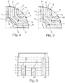
- the coefficient A corresponding to the configuration of the figure 2 is compared with the coefficients B and C of the configurations of Figures 4 and 5 , for which the angle ⁇ is respectively zero, the axes of the material bridges 10 being parallel to the radial axis X of the pole, and 15 ° in the opposite direction, the axes of the material bridges 10 being oriented away from the radial axis X of the corresponding pole of the rotor 1 when moving towards the air gap 11. It can be seen that the fatigue safety coefficient is maximum for the configuration according to the invention, where the Z axis is oriented towards the X axis of the corresponding pole when approaching the air gap.
- the rotor 1 may comprise permanent magnets 11 inserted in each of the housings, the magnets not being represented on the figure 1 but visible on the figure 7 their direction of magnetization being illustrated by arrows.
- Permanent magnets are in this example of generally rectangular shape in cross section. The placement of the magnets in the housing can leave a free space in each housing between the magnet and the short sides of the corresponding housing. The free space may be of generally triangular shape, as illustrated.
- some of the housing may be devoid of magnet.
- the housing of one of the rows are arranged in a central branch and two lateral branches, the central branch being only to include a permanent magnet, the lateral housing does not have a permanent magnet. In the example of the figure 7a , it's the contrary.
- the central recesses of a row may have a length L greater than that of the lateral recesses of said row, thus the lateral branches of the U are shorter than the central branch. It's also the opposite in the example of figure 7a .
- the Figures 7 and 7a also differ from the figure 1 in that the bridges of material 10 of the different rows have a variable width l , decreasing when approaching the gap 13.
- the longitudinal axes of two material bridges of two different rows are parallel to each other and offset by a non-zero distance d , for example approximately 1.5 mm, this offset taking place away from the radial axis when one moves away from the axis of rotation.
- the distance d is measured perpendicularly to said longitudinal axes Z.
- the Z axes of the bridges have been illustrated in FIG. figure 8 , and the shift of them to the figure 9 .
- the offset of the longitudinal axes of the bridges may be alternatively to the radial axis of the pole when moving away from the axis of rotation, in other words the offset is in the direction of the radial axis of the pole when the we are getting closer to the top of the pole.
- the longitudinal axes of two material bridges of two different rows are parallel to each other and coincide, when one is on the same side of the X axis.
- the rotor may comprise a single row of housings per pole, as illustrated by way of example not forming part of the invention in the figure 10 .
- the housings may each extend along a longitudinal axis which may be rectilinear, as illustrated above, or curve, as illustrated in FIG. figure 11 .
- the short sides of a housing may be rectilinear, as previously illustrated, or curved, as shown in FIG. figure 12 .
- All rows may have the same number of slots as previously described. It is not beyond the scope of the present invention if it is otherwise.
- we illustrated at the figure 13 an example in which two rows of the same pole have a different number of dwellings.
- a row of housing has two, namely the row closest to the air gap, and the other rows have three slots.
- the row closest to the gap has two housings arranged in V.
- the bridge 10 is thus central.
- the other two rows each comprise three housings arranged in flared U, each with two material bridges 10 symmetrical with respect to the radial axis X of the pole.
- the rotor can cooperate with any type of stator, distributed or concentrated winding.
Landscapes
- Engineering & Computer Science (AREA)
- Power Engineering (AREA)
- Permanent Field Magnets Of Synchronous Machinery (AREA)
- Iron Core Of Rotating Electric Machines (AREA)
Claims (15)
- Rotor (1) einer elektrischen Rotationsmaschine, mit einer Rotormasse (2), in der Aufnahmen (3) derart gebildet sind, dass Pole (4) des Rotors definiert werden, wobei jeder Pol eine radiale Polachse (X) hat,
wobei die Aufnahmen (3) eine längliche Form haben und jeweils zwei kurze Seiten (9) aufweisen, wobei die Ausnahmen in mehreren Reihen (6) je Pol angeordnet sind, die Aufnahmen in einer Reihe U-förmig angeordnet sind, wobei das U eine sich zum Luftspalt hin erweiternde Form haben kann,
wobei eine Reihe (6) wenigstens drei Aufnahmen (3) aufweist, die eine nach der anderen angeordnet sind und deren kurze Seiten (9) zischen zwei aufeinanderfolgenden Aufnahmen derselben Reihe eine Materialbrücke (10) begrenzen,wobei diese Materialbrücke (10) sich allgemein in Richtung einer Längsachse (Z) der Brücke erstreckt, die so orientiert ist, dass sie sich der radialen Achse (X) des entsprechenden Pols des Rotors annähert, wenn man sich von der Drehachse entfernt,dadurch gekennzeichnet, dass die kurzen Seiten einer Ausnehmung gerade sind, die Längsachsen von zwei Materialbrücken von zwei verschiedenen Reihen eines selben Pols zueinander parallel sind und einen Abstand (d) zu einander haben, der zwischen 0 (größer als Null) und 10 mm beträgt. - Rotor nach dem vorstehenden Anspruch, bei dem:a) (i) die seitlichen Arme jedes U kürzer sind als der mittlere Arm oder (ii) der mittlere Arm der einzige ist, der einen Permanentmagneten aufweist, und die den seitlichen Armen entsprechenden Aufnahmen keine Permanentmagneten aufweisen, undb) die Abweichung der Längsachsen der Brücken sich der radialen Achse des Pols nähert, wenn man sich von der Drehachse entfernt.
- Rotor nach Anspruch 1, bei dem:a) (i) die seitlichen Arme jedes U länger sind als der mittlere Arm oder (ii) die seitlichen Arme die einzigen sind, die einen Permanentmagneten aufweisen, und die dem mittleren Arm entsprechenden Aufnahmen keine Permanentmagneten aufweisen, undb) die Abweichung der Längsachsen der Brücken sich der radialen Achse des Pols nähert, wenn man sich von der Drehachse entfernt.
- Rotor nach einem der vorstehenden Ansprüche, bei dem die kurzen Seiten einer Ausnehmung gerade sind, die Materialbrücke (10) sich allgemein längs einer Längsachse (Z) der Brücke erstreckt, die mit einer radialen Achse (X) des entsprechenden Pols des Rotors einen Winkel (α) von weniger als 30° bildet.
- Rotor nach einem der vorstehenden Ansprüche, mit Permanentmagneten (11), die zumindest in einige der Aufnahmen eingesetzt sind.
- Rotor nach einem der vorstehenden Ansprüche, bei dem die Materialbrücke (10) sich allgemein längs einer Längsachse (2) der Brücke erstreckt, die mit einer radialen Achse (X) des entsprechenden Pols des Rotors einen Winkel (α) bildet, dessen Wert nicht null und größer als 5°, vorzugweise größer als 10° ist.
- Rotor nach einem der vorstehenden Ansprüche, bei dem wenigstens eine Reihe (4) eine ungerade Anzahl von Aufnahmen (3) aufweist, insbesondere wenigstens drei Aufnahmen.
- Rotor nach einem der vorstehenden Ansprüche, bei dem, wenn der Rotor (1) für ein und denselben Pol (4) mehrere Reihen (6) aufweist, diese letzteren von abnehmender Länge sind, wenn man sich in Richtung auf den Luftspalt bewegt.
- Rotor nach einem der vorstehenden Ansprüche, bei dem die Anordnung der Aufnahmen (3) und/oder der Materialbrücken (10) in einer Reihe symmetrisch in Bezug auf die radiale Achse (X) des Pols ist.
- Rotor nach einem der vorstehenden Ansprüche, bei dem die Materialbrücke (10) eine Breite (1) hat, gemessen rechtwinklig zu ihrer Längsachse, welche Breite kleiner ist als 8 mm und insbesondere größer als 0,5 mm sein kann.
- Rotor nach einem der vorstehenden Ansprüche, bei dem die Längsachsen (Z) der beiden Materialbrücken (10) der beiden verschiedenen Reihen (6) zueinander parallel sind.
- Rotor nach einem der vorstehenden Ansprüche, bei dem die Aufnahmen (3) eine allgemein trapezförmige Gestalt haben, wobei die kürzere der langen Seiten (14) der Aufnahme näher an dem Luftspalt liegt als die längere der langen Seiten.
- Rotor nach einem der vorstehenden Ansprüche, bei dem die Anzahl der Materialbrücken (10), die in einem Pol (4) schräg angeordnet sind, gleich der Anzahl der Aufnahmen in dem Pol ist, von der man die Anzahl der Reihen in diesem Pol abzieht.
- Rotor nach einem der vorstehenden Ansprüche, bei dem die Rotormasse (2) durch einen Stapel von Blechen gebildet ist, wobei jedes Blech der Rotormasse in einem Stück ausgebildet ist.
- Elektrische Rotationsmaschine mit einem Rotor (1) nach einem der vorstehenden Ansprüche.
Priority Applications (1)
| Application Number | Priority Date | Filing Date | Title |
|---|---|---|---|
| EP17167976.4A EP3288156A1 (de) | 2012-09-13 | 2013-09-12 | Elektrische maschine |
Applications Claiming Priority (2)
| Application Number | Priority Date | Filing Date | Title |
|---|---|---|---|
| FR1258587A FR2995469B1 (fr) | 2012-09-13 | 2012-09-13 | Rotor de machine electrique tournante, comportant une masse rotorique dans laquelle sont menages des logements. |
| PCT/IB2013/058500 WO2014041507A1 (fr) | 2012-09-13 | 2013-09-12 | Rotor de machine electrique tournante, comportant une masse rotorique dans laquelle sont menages des logements |
Related Child Applications (2)
| Application Number | Title | Priority Date | Filing Date |
|---|---|---|---|
| EP17167976.4A Division EP3288156A1 (de) | 2012-09-13 | 2013-09-12 | Elektrische maschine |
| EP17167976.4A Division-Into EP3288156A1 (de) | 2012-09-13 | 2013-09-12 | Elektrische maschine |
Publications (3)
| Publication Number | Publication Date |
|---|---|
| EP2896114A1 EP2896114A1 (de) | 2015-07-22 |
| EP2896114B1 true EP2896114B1 (de) | 2017-07-05 |
| EP2896114B2 EP2896114B2 (de) | 2020-11-25 |
Family
ID=48050817
Family Applications (2)
| Application Number | Title | Priority Date | Filing Date |
|---|---|---|---|
| EP13795859.1A Active EP2896114B2 (de) | 2012-09-13 | 2013-09-12 | Rotor einer elektrischen rotationsmaschine mit einem läuferkörper mit aussparungen |
| EP17167976.4A Withdrawn EP3288156A1 (de) | 2012-09-13 | 2013-09-12 | Elektrische maschine |
Family Applications After (1)
| Application Number | Title | Priority Date | Filing Date |
|---|---|---|---|
| EP17167976.4A Withdrawn EP3288156A1 (de) | 2012-09-13 | 2013-09-12 | Elektrische maschine |
Country Status (6)
| Country | Link |
|---|---|
| US (1) | US10491063B2 (de) |
| EP (2) | EP2896114B2 (de) |
| CN (1) | CN104620473B (de) |
| BR (1) | BR112015005561A2 (de) |
| FR (1) | FR2995469B1 (de) |
| WO (1) | WO2014041507A1 (de) |
Families Citing this family (27)
| Publication number | Priority date | Publication date | Assignee | Title |
|---|---|---|---|---|
| DE112014006430B4 (de) | 2014-03-05 | 2024-05-29 | Mitsubishi Electric Corporation | Synchron-Reluktanzmotor |
| JP2015186383A (ja) * | 2014-03-25 | 2015-10-22 | アイシン・エィ・ダブリュ株式会社 | 回転電機のロータ |
| JP6366986B2 (ja) | 2014-04-11 | 2018-08-01 | 株式会社東芝 | 同期リラクタンス型回転電機 |
| CN106030989B (zh) * | 2014-08-11 | 2018-09-11 | 富士电机株式会社 | 旋转电机 |
| WO2016024325A1 (ja) * | 2014-08-11 | 2016-02-18 | 富士電機株式会社 | 回転電機 |
| ITUB20150608A1 (it) * | 2015-04-14 | 2016-10-14 | Ge Avio Srl | Metodo di realizzazione di una struttura di rotore di una macchina elettrica sincrona a riluttanza, e relativa macchina elettrica sincrona a riluttanza |
| FR3035552B1 (fr) * | 2015-04-23 | 2019-05-24 | IFP Energies Nouvelles | Machine electrique et procede pour l'equilibrage dynamique du rotor de cette machine electrique. |
| JP6451517B2 (ja) * | 2015-06-10 | 2019-01-16 | 株式会社デンソー | ロータ |
| ITUA20162566A1 (it) * | 2016-04-13 | 2017-10-13 | S M E S P A | Rotore per una macchina sincrona e macchina sincrona comprendente tale rotore |
| JP6747064B2 (ja) * | 2016-06-02 | 2020-08-26 | 株式会社明電舎 | 永久磁石式回転電機 |
| CN106329773B (zh) * | 2016-08-31 | 2018-11-27 | 恒大法拉第未来智能汽车(广东)有限公司 | 电机的转子、电机及车辆 |
| EP3560073A1 (de) * | 2016-12-21 | 2019-10-30 | ABB Schweiz AG | Rotor für elektrische drehmaschinen |
| WO2018131393A1 (ja) * | 2017-01-12 | 2018-07-19 | アイシン・エィ・ダブリュ株式会社 | 回転電機用ロータ |
| US10715017B2 (en) * | 2017-06-02 | 2020-07-14 | Hamilton Sundstrand Corporation | Hybrid synchronous machines |
| CN107394922B (zh) * | 2017-08-24 | 2023-11-14 | 智车优行科技(上海)有限公司 | 内置式永磁电机转子和永磁电机 |
| FR3071370B1 (fr) * | 2017-09-18 | 2019-09-13 | IFP Energies Nouvelles | Isthmes de ponts magnetiques d'un rotor de machine electrique |
| CN108777520B (zh) * | 2018-07-17 | 2020-03-27 | 珠海格力电器股份有限公司 | 一种交替极电机 |
| FR3084534B1 (fr) | 2018-07-24 | 2020-07-17 | IFP Energies Nouvelles | Rotor de machine electrique avec ponts magnetiques asymetriques |
| CN109067039A (zh) * | 2018-09-12 | 2018-12-21 | 南京航空航天大学 | 一种非对称蝴蝶型内置式永磁同步电机 |
| FR3094583B1 (fr) * | 2019-03-29 | 2021-03-12 | Ifp Energies Now | Rotor de machine électrique avec pôles asymétriques et aimants latéraux |
| WO2021162771A1 (en) * | 2020-02-14 | 2021-08-19 | Gentiam Llc | A wide-speed multiple interior rotor excitation machine |
| US12266977B2 (en) | 2020-04-15 | 2025-04-01 | Panasonic Intellectual Property Management Co., Ltd. | Rotor and electric motor |
| FR3120168B1 (fr) * | 2021-02-22 | 2025-02-21 | Nidec Psa Emotors | Rotor de machine électrique tournante |
| FR3121294B1 (fr) * | 2021-03-29 | 2024-07-12 | Nidec Psa Emotors | Rotor de machine électrique tournante |
| IT202100028502A1 (it) * | 2021-11-10 | 2023-05-10 | Eldor Corp Spa | Motore elettrico |
| JP7773957B2 (ja) * | 2022-09-26 | 2025-11-20 | 株式会社日立インダストリアルプロダクツ | 回転電機、並びに電動車両 |
| DE102024108047A1 (de) * | 2024-03-21 | 2025-09-25 | Schaeffler Technologies AG & Co. KG | Permanentmagneterregter Rotor und elektrische Maschine |
Citations (6)
| Publication number | Priority date | Publication date | Assignee | Title |
|---|---|---|---|---|
| EP0746079A2 (de) | 1995-05-31 | 1996-12-04 | Matsushita Electric Industrial Co., Ltd. | Motor mit eingebauten Permanentmagneten |
| JP2003158838A (ja) | 2001-11-20 | 2003-05-30 | Aisin Seiki Co Ltd | 永久磁石型同期機 |
| WO2007055775A2 (en) | 2005-10-31 | 2007-05-18 | Caterpillar Inc. | Rotary electric machine |
| US7498708B2 (en) | 2004-10-26 | 2009-03-03 | Kollmorgen Corporation | Design of the magnet and webs in interior permanent magnet rotors |
| US20090224624A1 (en) | 2008-03-06 | 2009-09-10 | Ajith Kuttannair Kumar | Rotor structure for interior permanent magnet electromotive machine |
| WO2012004761A2 (en) | 2010-07-09 | 2012-01-12 | Brusa Elektronik Ag | Laminated rotor for rotating electric machine, in particular for hybrid synchronous motor of vehicle drives |
Family Cites Families (17)
| Publication number | Priority date | Publication date | Assignee | Title |
|---|---|---|---|---|
| JP2000050542A (ja) | 1998-07-23 | 2000-02-18 | Okuma Corp | リラクタンスモータ |
| JP2002010547A (ja) | 2000-06-16 | 2002-01-11 | Yamaha Motor Co Ltd | 永久磁石回転子及びその製造方法 |
| JP2002354730A (ja) | 2001-05-25 | 2002-12-06 | Hitachi Ltd | 永久磁石式回転電機 |
| JP2003032926A (ja) * | 2001-07-10 | 2003-01-31 | Teijin Seiki Co Ltd | 永久磁石型モータ |
| JP2003242163A (ja) * | 2002-02-19 | 2003-08-29 | Canon Inc | 画像記録装置、情報処理装置、情報処理方法及びプログラム |
| US6703746B2 (en) * | 2002-03-01 | 2004-03-09 | General Motors Corporation | Interior permanent magnet rotor |
| US20060004381A1 (en) * | 2004-07-01 | 2006-01-05 | Vladimir Feingold | Intracorneal lens insertion device |
| KR100591338B1 (ko) * | 2004-08-26 | 2006-06-19 | 엘지전자 주식회사 | 영구자석 보조형 동기 릴럭턴스 모터 및 그 착자방법 |
| US7705503B2 (en) | 2005-09-07 | 2010-04-27 | Kabushiki Kaisha Toshiba | Rotating electrical machine |
| US7779153B2 (en) | 2005-10-27 | 2010-08-17 | Cochlear Limited | Automated collection of operational data from distributed medical devices |
| US7556082B2 (en) * | 2006-03-29 | 2009-07-07 | Gm Global Technology Operations, Inc. | Interior permanent magnet rotors with multiple properties and methods of making same |
| JP4404223B2 (ja) | 2007-03-20 | 2010-01-27 | 株式会社安川電機 | 電磁鋼板形成体、電磁鋼板積層体、これを備えた永久磁石形同期回転電機用回転子、永久磁石形同期回転電機、該回転電機を用いた車両、昇降機、流体機械、加工機 |
| CN201312221Y (zh) * | 2008-07-31 | 2009-09-16 | 上海电科电机科技有限公司 | 一种内置式永磁同步电动机转子结构 |
| US7902710B2 (en) * | 2008-10-01 | 2011-03-08 | Caterpillar Inc. | Electric machine |
| US7902711B2 (en) * | 2008-12-09 | 2011-03-08 | GM Global Technology Operations LLC | Methods and apparatus for a permanent magnet machine with segmented ferrite magnets |
| WO2011001533A1 (ja) * | 2009-07-03 | 2011-01-06 | 三菱電機株式会社 | 永久磁石型回転電機 |
| CN102474165B (zh) | 2009-08-06 | 2015-09-30 | 株式会社东芝 | 永磁体、以及使用永磁体的可变磁通电动机及发电机 |
-
2012
- 2012-09-13 FR FR1258587A patent/FR2995469B1/fr active Active
-
2013
- 2013-09-12 CN CN201380047922.1A patent/CN104620473B/zh not_active Expired - Fee Related
- 2013-09-12 US US14/428,134 patent/US10491063B2/en active Active
- 2013-09-12 EP EP13795859.1A patent/EP2896114B2/de active Active
- 2013-09-12 WO PCT/IB2013/058500 patent/WO2014041507A1/fr not_active Ceased
- 2013-09-12 BR BR112015005561A patent/BR112015005561A2/pt not_active Application Discontinuation
- 2013-09-12 EP EP17167976.4A patent/EP3288156A1/de not_active Withdrawn
Patent Citations (6)
| Publication number | Priority date | Publication date | Assignee | Title |
|---|---|---|---|---|
| EP0746079A2 (de) | 1995-05-31 | 1996-12-04 | Matsushita Electric Industrial Co., Ltd. | Motor mit eingebauten Permanentmagneten |
| JP2003158838A (ja) | 2001-11-20 | 2003-05-30 | Aisin Seiki Co Ltd | 永久磁石型同期機 |
| US7498708B2 (en) | 2004-10-26 | 2009-03-03 | Kollmorgen Corporation | Design of the magnet and webs in interior permanent magnet rotors |
| WO2007055775A2 (en) | 2005-10-31 | 2007-05-18 | Caterpillar Inc. | Rotary electric machine |
| US20090224624A1 (en) | 2008-03-06 | 2009-09-10 | Ajith Kuttannair Kumar | Rotor structure for interior permanent magnet electromotive machine |
| WO2012004761A2 (en) | 2010-07-09 | 2012-01-12 | Brusa Elektronik Ag | Laminated rotor for rotating electric machine, in particular for hybrid synchronous motor of vehicle drives |
Also Published As
| Publication number | Publication date |
|---|---|
| EP3288156A1 (de) | 2018-02-28 |
| FR2995469B1 (fr) | 2017-04-21 |
| US10491063B2 (en) | 2019-11-26 |
| FR2995469A1 (fr) | 2014-03-14 |
| CN104620473A (zh) | 2015-05-13 |
| WO2014041507A1 (fr) | 2014-03-20 |
| EP2896114A1 (de) | 2015-07-22 |
| US20150229170A1 (en) | 2015-08-13 |
| BR112015005561A2 (pt) | 2017-10-10 |
| EP2896114B2 (de) | 2020-11-25 |
| CN104620473B (zh) | 2019-04-19 |
Similar Documents
| Publication | Publication Date | Title |
|---|---|---|
| EP2896114B2 (de) | Rotor einer elektrischen rotationsmaschine mit einem läuferkörper mit aussparungen | |
| FR2932618A1 (fr) | Rotor a aimants permanents et machine tournante comportant un tel rotor | |
| EP3130059A2 (de) | Rotor für eine elektrische drehmaschine | |
| EP2715917A1 (de) | Permanentmagnetrotor und drehmaschine mit einem solchen rotor | |
| EP3130060A2 (de) | Rotor für eine elektrische drehmaschine | |
| EP3130061B1 (de) | Stator für eine drehende elektrische maschine | |
| WO2015075364A2 (fr) | Lames de maintien des aimants | |
| EP2817868A1 (de) | Rotor einer rotierenden maschine mit flusskonzentration | |
| EP2965404A2 (de) | Rotierende elektrische maschine mit eingebetteten permanentmagneten | |
| FR3014255A1 (fr) | Rotor discoide a structure composite renforcee pour machine electrique a flux axial | |
| WO2014072618A1 (fr) | Moteur electrique synchrone a aimants permanents et compresseur electrique comportant un tel moteur electrique | |
| FR3015794A1 (fr) | Element de machine electromagnetique a circuits electromagnetiques optimises integres a des pistes sous forme de lignes crenelees annulaires | |
| FR3107999A1 (fr) | Rotor pour machine électromagnétique à flux axial | |
| EP2957019B1 (de) | Rotierende elektrische maschine mit eingelassenen permanentmagneten | |
| EP2878071B1 (de) | Wicklung für ein statorelement eines permanentmagnetmotors oder generators mit mindestens einem einkomponentigen starren glied und herstellungsverfahren dafür | |
| EP3639349B1 (de) | Rotierende elektrische maschine | |
| EP3387742B1 (de) | Rotor für einen elektromagnetischen axialflussmotor mit welligem integriertem magnet | |
| WO2019073128A1 (fr) | Rotor pour moteur ou génératrice électromagnétique à rigidité diminuée | |
| FR2895844A1 (fr) | Machine electrique tournante comportant des pieces polaires et des aimants permanents | |
| EP4113796A1 (de) | Elektrische umlaufende maschine | |
| FR3152198A1 (fr) | Moteur électrique à flux axial amélioré | |
| FR3155944A1 (fr) | Structure d’aimant à aimants unitaires présentant une section en forme de losange | |
| EP2781006A2 (de) | Läufer einer elektrischen drehmaschine mit flusskonzentration | |
| EP4038723A1 (de) | Rotor für eine rotierende elektrische maschine | |
| FR3074375A1 (fr) | Rotor cylindrique a champ radial, et machine electrique et/ou magnetique comprenant un tel rotor |
Legal Events
| Date | Code | Title | Description |
|---|---|---|---|
| PUAI | Public reference made under article 153(3) epc to a published international application that has entered the european phase |
Free format text: ORIGINAL CODE: 0009012 |
|
| 17P | Request for examination filed |
Effective date: 20150413 |
|
| AK | Designated contracting states |
Kind code of ref document: A1 Designated state(s): AL AT BE BG CH CY CZ DE DK EE ES FI FR GB GR HR HU IE IS IT LI LT LU LV MC MK MT NL NO PL PT RO RS SE SI SK SM TR |
|
| AX | Request for extension of the european patent |
Extension state: BA ME |
|
| DAX | Request for extension of the european patent (deleted) | ||
| 17Q | First examination report despatched |
Effective date: 20160720 |
|
| STAA | Information on the status of an ep patent application or granted ep patent |
Free format text: STATUS: EXAMINATION IS IN PROGRESS |
|
| GRAP | Despatch of communication of intention to grant a patent |
Free format text: ORIGINAL CODE: EPIDOSNIGR1 |
|
| STAA | Information on the status of an ep patent application or granted ep patent |
Free format text: STATUS: GRANT OF PATENT IS INTENDED |
|
| INTG | Intention to grant announced |
Effective date: 20170208 |
|
| GRAS | Grant fee paid |
Free format text: ORIGINAL CODE: EPIDOSNIGR3 |
|
| GRAA | (expected) grant |
Free format text: ORIGINAL CODE: 0009210 |
|
| STAA | Information on the status of an ep patent application or granted ep patent |
Free format text: STATUS: THE PATENT HAS BEEN GRANTED |
|
| AK | Designated contracting states |
Kind code of ref document: B1 Designated state(s): AL AT BE BG CH CY CZ DE DK EE ES FI FR GB GR HR HU IE IS IT LI LT LU LV MC MK MT NL NO PL PT RO RS SE SI SK SM TR |
|
| REG | Reference to a national code |
Ref country code: GB Ref legal event code: FG4D Free format text: NOT ENGLISH |
|
| REG | Reference to a national code |
Ref country code: CH Ref legal event code: EP |
|
| REG | Reference to a national code |
Ref country code: AT Ref legal event code: REF Ref document number: 907222 Country of ref document: AT Kind code of ref document: T Effective date: 20170715 |
|
| REG | Reference to a national code |
Ref country code: IE Ref legal event code: FG4D Free format text: LANGUAGE OF EP DOCUMENT: FRENCH |
|
| REG | Reference to a national code |
Ref country code: DE Ref legal event code: R096 Ref document number: 602013023182 Country of ref document: DE |
|
| REG | Reference to a national code |
Ref country code: FR Ref legal event code: PLFP Year of fee payment: 5 |
|
| REG | Reference to a national code |
Ref country code: NL Ref legal event code: MP Effective date: 20170705 |
|
| REG | Reference to a national code |
Ref country code: AT Ref legal event code: MK05 Ref document number: 907222 Country of ref document: AT Kind code of ref document: T Effective date: 20170705 |
|
| REG | Reference to a national code |
Ref country code: LT Ref legal event code: MG4D |
|
| PG25 | Lapsed in a contracting state [announced via postgrant information from national office to epo] |
Ref country code: FI Free format text: LAPSE BECAUSE OF FAILURE TO SUBMIT A TRANSLATION OF THE DESCRIPTION OR TO PAY THE FEE WITHIN THE PRESCRIBED TIME-LIMIT Effective date: 20170705 Ref country code: NO Free format text: LAPSE BECAUSE OF FAILURE TO SUBMIT A TRANSLATION OF THE DESCRIPTION OR TO PAY THE FEE WITHIN THE PRESCRIBED TIME-LIMIT Effective date: 20171005 Ref country code: AT Free format text: LAPSE BECAUSE OF FAILURE TO SUBMIT A TRANSLATION OF THE DESCRIPTION OR TO PAY THE FEE WITHIN THE PRESCRIBED TIME-LIMIT Effective date: 20170705 Ref country code: HR Free format text: LAPSE BECAUSE OF FAILURE TO SUBMIT A TRANSLATION OF THE DESCRIPTION OR TO PAY THE FEE WITHIN THE PRESCRIBED TIME-LIMIT Effective date: 20170705 Ref country code: SE Free format text: LAPSE BECAUSE OF FAILURE TO SUBMIT A TRANSLATION OF THE DESCRIPTION OR TO PAY THE FEE WITHIN THE PRESCRIBED TIME-LIMIT Effective date: 20170705 Ref country code: LT Free format text: LAPSE BECAUSE OF FAILURE TO SUBMIT A TRANSLATION OF THE DESCRIPTION OR TO PAY THE FEE WITHIN THE PRESCRIBED TIME-LIMIT Effective date: 20170705 Ref country code: NL Free format text: LAPSE BECAUSE OF FAILURE TO SUBMIT A TRANSLATION OF THE DESCRIPTION OR TO PAY THE FEE WITHIN THE PRESCRIBED TIME-LIMIT Effective date: 20170705 |
|
| PG25 | Lapsed in a contracting state [announced via postgrant information from national office to epo] |
Ref country code: RS Free format text: LAPSE BECAUSE OF FAILURE TO SUBMIT A TRANSLATION OF THE DESCRIPTION OR TO PAY THE FEE WITHIN THE PRESCRIBED TIME-LIMIT Effective date: 20170705 Ref country code: IS Free format text: LAPSE BECAUSE OF FAILURE TO SUBMIT A TRANSLATION OF THE DESCRIPTION OR TO PAY THE FEE WITHIN THE PRESCRIBED TIME-LIMIT Effective date: 20171105 Ref country code: PL Free format text: LAPSE BECAUSE OF FAILURE TO SUBMIT A TRANSLATION OF THE DESCRIPTION OR TO PAY THE FEE WITHIN THE PRESCRIBED TIME-LIMIT Effective date: 20170705 Ref country code: GR Free format text: LAPSE BECAUSE OF FAILURE TO SUBMIT A TRANSLATION OF THE DESCRIPTION OR TO PAY THE FEE WITHIN THE PRESCRIBED TIME-LIMIT Effective date: 20171006 Ref country code: LV Free format text: LAPSE BECAUSE OF FAILURE TO SUBMIT A TRANSLATION OF THE DESCRIPTION OR TO PAY THE FEE WITHIN THE PRESCRIBED TIME-LIMIT Effective date: 20170705 Ref country code: BG Free format text: LAPSE BECAUSE OF FAILURE TO SUBMIT A TRANSLATION OF THE DESCRIPTION OR TO PAY THE FEE WITHIN THE PRESCRIBED TIME-LIMIT Effective date: 20171005 Ref country code: ES Free format text: LAPSE BECAUSE OF FAILURE TO SUBMIT A TRANSLATION OF THE DESCRIPTION OR TO PAY THE FEE WITHIN THE PRESCRIBED TIME-LIMIT Effective date: 20170705 |
|
| REG | Reference to a national code |
Ref country code: DE Ref legal event code: R026 Ref document number: 602013023182 Country of ref document: DE |
|
| PLBI | Opposition filed |
Free format text: ORIGINAL CODE: 0009260 |
|
| PLAX | Notice of opposition and request to file observation + time limit sent |
Free format text: ORIGINAL CODE: EPIDOSNOBS2 |
|
| PG25 | Lapsed in a contracting state [announced via postgrant information from national office to epo] |
Ref country code: CZ Free format text: LAPSE BECAUSE OF FAILURE TO SUBMIT A TRANSLATION OF THE DESCRIPTION OR TO PAY THE FEE WITHIN THE PRESCRIBED TIME-LIMIT Effective date: 20170705 Ref country code: DK Free format text: LAPSE BECAUSE OF FAILURE TO SUBMIT A TRANSLATION OF THE DESCRIPTION OR TO PAY THE FEE WITHIN THE PRESCRIBED TIME-LIMIT Effective date: 20170705 Ref country code: RO Free format text: LAPSE BECAUSE OF FAILURE TO SUBMIT A TRANSLATION OF THE DESCRIPTION OR TO PAY THE FEE WITHIN THE PRESCRIBED TIME-LIMIT Effective date: 20170705 |
|
| REG | Reference to a national code |
Ref country code: CH Ref legal event code: PL |
|
| 26 | Opposition filed |
Opponent name: ABB SCHWEIZ AG Effective date: 20180405 |
|
| PG25 | Lapsed in a contracting state [announced via postgrant information from national office to epo] |
Ref country code: SK Free format text: LAPSE BECAUSE OF FAILURE TO SUBMIT A TRANSLATION OF THE DESCRIPTION OR TO PAY THE FEE WITHIN THE PRESCRIBED TIME-LIMIT Effective date: 20170705 Ref country code: SM Free format text: LAPSE BECAUSE OF FAILURE TO SUBMIT A TRANSLATION OF THE DESCRIPTION OR TO PAY THE FEE WITHIN THE PRESCRIBED TIME-LIMIT Effective date: 20170705 Ref country code: MC Free format text: LAPSE BECAUSE OF FAILURE TO SUBMIT A TRANSLATION OF THE DESCRIPTION OR TO PAY THE FEE WITHIN THE PRESCRIBED TIME-LIMIT Effective date: 20170705 Ref country code: EE Free format text: LAPSE BECAUSE OF FAILURE TO SUBMIT A TRANSLATION OF THE DESCRIPTION OR TO PAY THE FEE WITHIN THE PRESCRIBED TIME-LIMIT Effective date: 20170705 |
|
| REG | Reference to a national code |
Ref country code: IE Ref legal event code: MM4A |
|
| REG | Reference to a national code |
Ref country code: BE Ref legal event code: MM Effective date: 20170930 |
|
| PG25 | Lapsed in a contracting state [announced via postgrant information from national office to epo] |
Ref country code: LU Free format text: LAPSE BECAUSE OF NON-PAYMENT OF DUE FEES Effective date: 20170912 |
|
| REG | Reference to a national code |
Ref country code: FR Ref legal event code: PLFP Year of fee payment: 6 |
|
| PG25 | Lapsed in a contracting state [announced via postgrant information from national office to epo] |
Ref country code: LI Free format text: LAPSE BECAUSE OF NON-PAYMENT OF DUE FEES Effective date: 20170930 Ref country code: IE Free format text: LAPSE BECAUSE OF NON-PAYMENT OF DUE FEES Effective date: 20170912 Ref country code: CH Free format text: LAPSE BECAUSE OF NON-PAYMENT OF DUE FEES Effective date: 20170930 |
|
| PLBB | Reply of patent proprietor to notice(s) of opposition received |
Free format text: ORIGINAL CODE: EPIDOSNOBS3 |
|
| PG25 | Lapsed in a contracting state [announced via postgrant information from national office to epo] |
Ref country code: BE Free format text: LAPSE BECAUSE OF NON-PAYMENT OF DUE FEES Effective date: 20170930 Ref country code: SI Free format text: LAPSE BECAUSE OF FAILURE TO SUBMIT A TRANSLATION OF THE DESCRIPTION OR TO PAY THE FEE WITHIN THE PRESCRIBED TIME-LIMIT Effective date: 20170705 |
|
| PG25 | Lapsed in a contracting state [announced via postgrant information from national office to epo] |
Ref country code: MT Free format text: LAPSE BECAUSE OF FAILURE TO SUBMIT A TRANSLATION OF THE DESCRIPTION OR TO PAY THE FEE WITHIN THE PRESCRIBED TIME-LIMIT Effective date: 20170705 |
|
| PG25 | Lapsed in a contracting state [announced via postgrant information from national office to epo] |
Ref country code: HU Free format text: LAPSE BECAUSE OF FAILURE TO SUBMIT A TRANSLATION OF THE DESCRIPTION OR TO PAY THE FEE WITHIN THE PRESCRIBED TIME-LIMIT; INVALID AB INITIO Effective date: 20130912 |
|
| PG25 | Lapsed in a contracting state [announced via postgrant information from national office to epo] |
Ref country code: CY Free format text: LAPSE BECAUSE OF FAILURE TO SUBMIT A TRANSLATION OF THE DESCRIPTION OR TO PAY THE FEE WITHIN THE PRESCRIBED TIME-LIMIT Effective date: 20170705 |
|
| PG25 | Lapsed in a contracting state [announced via postgrant information from national office to epo] |
Ref country code: MK Free format text: LAPSE BECAUSE OF FAILURE TO SUBMIT A TRANSLATION OF THE DESCRIPTION OR TO PAY THE FEE WITHIN THE PRESCRIBED TIME-LIMIT Effective date: 20170705 |
|
| APBM | Appeal reference recorded |
Free format text: ORIGINAL CODE: EPIDOSNREFNO |
|
| APBP | Date of receipt of notice of appeal recorded |
Free format text: ORIGINAL CODE: EPIDOSNNOA2O |
|
| PG25 | Lapsed in a contracting state [announced via postgrant information from national office to epo] |
Ref country code: TR Free format text: LAPSE BECAUSE OF FAILURE TO SUBMIT A TRANSLATION OF THE DESCRIPTION OR TO PAY THE FEE WITHIN THE PRESCRIBED TIME-LIMIT Effective date: 20170705 |
|
| APAH | Appeal reference modified |
Free format text: ORIGINAL CODE: EPIDOSCREFNO |
|
| PG25 | Lapsed in a contracting state [announced via postgrant information from national office to epo] |
Ref country code: PT Free format text: LAPSE BECAUSE OF FAILURE TO SUBMIT A TRANSLATION OF THE DESCRIPTION OR TO PAY THE FEE WITHIN THE PRESCRIBED TIME-LIMIT Effective date: 20170705 |
|
| APBU | Appeal procedure closed |
Free format text: ORIGINAL CODE: EPIDOSNNOA9O |
|
| PG25 | Lapsed in a contracting state [announced via postgrant information from national office to epo] |
Ref country code: AL Free format text: LAPSE BECAUSE OF FAILURE TO SUBMIT A TRANSLATION OF THE DESCRIPTION OR TO PAY THE FEE WITHIN THE PRESCRIBED TIME-LIMIT Effective date: 20170705 |
|
| PUAH | Patent maintained in amended form |
Free format text: ORIGINAL CODE: 0009272 |
|
| STAA | Information on the status of an ep patent application or granted ep patent |
Free format text: STATUS: PATENT MAINTAINED AS AMENDED |
|
| 27A | Patent maintained in amended form |
Effective date: 20201125 |
|
| AK | Designated contracting states |
Kind code of ref document: B2 Designated state(s): AL AT BE BG CH CY CZ DE DK EE ES FI FR GB GR HR HU IE IS IT LI LT LU LV MC MK MT NL NO PL PT RO RS SE SI SK SM TR |
|
| REG | Reference to a national code |
Ref country code: DE Ref legal event code: R102 Ref document number: 602013023182 Country of ref document: DE |
|
| PGFP | Annual fee paid to national office [announced via postgrant information from national office to epo] |
Ref country code: DE Payment date: 20250919 Year of fee payment: 13 |
|
| PGFP | Annual fee paid to national office [announced via postgrant information from national office to epo] |
Ref country code: IT Payment date: 20250923 Year of fee payment: 13 |
|
| PGFP | Annual fee paid to national office [announced via postgrant information from national office to epo] |
Ref country code: GB Payment date: 20250918 Year of fee payment: 13 |
|
| PGFP | Annual fee paid to national office [announced via postgrant information from national office to epo] |
Ref country code: FR Payment date: 20250922 Year of fee payment: 13 |