EP2896114B2 - Rotor de machine électrique tournante, comportant une masse rotorique dans laquelle sont ménagés des logements - Google Patents
Rotor de machine électrique tournante, comportant une masse rotorique dans laquelle sont ménagés des logements Download PDFInfo
- Publication number
- EP2896114B2 EP2896114B2 EP13795859.1A EP13795859A EP2896114B2 EP 2896114 B2 EP2896114 B2 EP 2896114B2 EP 13795859 A EP13795859 A EP 13795859A EP 2896114 B2 EP2896114 B2 EP 2896114B2
- Authority
- EP
- European Patent Office
- Prior art keywords
- rotor
- pole
- recesses
- bridges
- axis
- Prior art date
- Legal status (The legal status is an assumption and is not a legal conclusion. Google has not performed a legal analysis and makes no representation as to the accuracy of the status listed.)
- Active
Links
Images


Classifications
-
- H—ELECTRICITY
- H02—GENERATION; CONVERSION OR DISTRIBUTION OF ELECTRIC POWER
- H02K—DYNAMO-ELECTRIC MACHINES
- H02K1/00—Details of the magnetic circuit
- H02K1/06—Details of the magnetic circuit characterised by the shape, form or construction
- H02K1/22—Rotating parts of the magnetic circuit
- H02K1/27—Rotor cores with permanent magnets
- H02K1/2706—Inner rotors
- H02K1/272—Inner rotors the magnetisation axis of the magnets being perpendicular to the rotor axis
- H02K1/274—Inner rotors the magnetisation axis of the magnets being perpendicular to the rotor axis the rotor consisting of two or more circumferentially positioned magnets
- H02K1/2753—Inner rotors the magnetisation axis of the magnets being perpendicular to the rotor axis the rotor consisting of two or more circumferentially positioned magnets the rotor consisting of magnets or groups of magnets arranged with alternating polarity
- H02K1/276—Magnets embedded in the magnetic core, e.g. interior permanent magnets [IPM]
- H02K1/2766—Magnets embedded in the magnetic core, e.g. interior permanent magnets [IPM] having a flux concentration effect
-
- H—ELECTRICITY
- H02—GENERATION; CONVERSION OR DISTRIBUTION OF ELECTRIC POWER
- H02K—DYNAMO-ELECTRIC MACHINES
- H02K2213/00—Specific aspects, not otherwise provided for and not covered by codes H02K2201/00 - H02K2211/00
- H02K2213/03—Machines characterised by numerical values, ranges, mathematical expressions or similar information
Definitions
- the present invention relates to rotating electrical machines and in particular to those comprising a flux concentration rotor, and more particularly to the rotors of such machines.
- Rotating electrical machines comprising a rotor which comprises magnets arranged in housings so as to define the poles of the rotor.
- the housings can be in the form of a circular arc or V. They are separated from the air gap by circumferentially oriented bridges of material, which make it possible to maintain the cohesion of the rotor against the mechanical forces to which the machine is subjected.
- the demand EP 1 276 204 relates to a permanent magnet motor in which the permanent magnets are arranged in a single row.
- the invention aims to meet this need and thus has as an object, according to a first of its aspects according to claim 1, a rotor of a rotating electrical machine comprising a rotor mass in which housings are formed so as to define the poles of the rotor.
- each pole having a radial axis of the pole
- the housings being of elongated shape and each comprising two short sides, the housings being arranged in several rows per pole, one row comprising at least three housings arranged consecutively, their short sides defining between two housings consecutive in the same row a material bridge, this material bridge generally extending along a longitudinal axis of the bridge oriented obliquely towards the radial axis of the corresponding pole of the rotor, when moving away of the axis of rotation.
- the rotor according to the invention makes it possible to reconcile the aforementioned contradictory requirements, that is to say on the one hand the circulation of the flux in the magnetic circuit, and on the other hand the mechanical strength of the rotor.
- the obliquely oriented material bridges mentioned above make it possible to withstand the centrifugal forces to which the rotor may be subjected, without penalizing the machine on the magnetic level.
- the rotor has permanent magnets inserted in all the housings.
- Permanent magnets can be made of ferrites or with rare earths or with any other type of magnetic material.
- the arrangement of the housings makes it possible to concentrate the flux of the magnets and to obtain interesting performances with ferrite magnets.
- the housings of the same row are arranged in a central branch and two lateral branches located on either side of the central branch, for example giving a U-shaped configuration, the central branch being for example alone. to include one or more permanent magnets, the side branches not housing a permanent magnet.
- radial axis of the pole is meant an axis of the pole oriented radially, that is to say along a radius of the rotor. It can be an axis of symmetry for the pole. This radial axis can intersect the top of the pole.
- the bridges of material formed between the housings extend obliquely along a longitudinal axis of the bridge which forms with the radial axis of the corresponding pole of the rotor an angle of a non-zero value greater than 5 °. better greater than 10 °. for example of the order of about 15 °.
- the angle is less than 45 °, better still less than 30 °, or even less than 20 °.
- longitudinal axis of the bridge is meant the axis arranged centrally with respect to the two short sides of the adjacent housings defining this bridge of matter. This axis is preferably rectilinear.
- the concavity of the row can be oriented towards the top of the pole, ie towards the air gap.
- the housings of this pole are arranged in several rows, each with a concavity which can be oriented towards the top of the pole, in particular in substantially concentric rows.
- the term “concentric” is understood to mean that the median axes of the housings of the rows, taken in a plane perpendicular to the axis of rotation of the rotor, intersect at the same point. This arrangement in several concentric rows makes it possible to improve the concentration of the flux without necessarily having to increase the size of the housings or the quantity of permanent magnets necessary to obtain an equivalent flux.
- the number of rows per pole can in particular be two, three or four.
- the rotor When the rotor has several rows for the same pole, the latter may be of decreasing length when moving in the direction of the air gap, the longest being closer to the axis of rotation and the shorter on the side of the air gap.
- the length of a row is the cumulative length of the slots in that row.
- At least two housings of two rows of the same pole can extend parallel to one another. All of the housings in one row may extend parallel to the corresponding housings in another row.
- the rotor can include as many obliquely oriented bridges of material as there are rows of housings, or even up to twice as many, or even three times as many.
- the number of obliquely oriented material bridges in a pole may be equal to the number of housings in the pole, from which the number of rows in said pole is subtracted.
- a row has at least three dwellings.
- a row may for example include a central housing and two side housings.
- At least one row can include an odd number of housings, for example at least three housings.
- At least one pole comprises a row of housings comprising a lower number of housings than those of another row of this pole, for example two against three for the other row.
- the row with the lowest number of housings is preferably the one closest to the air gap and the furthest from the axis of rotation.
- the arrangement of the housings and / or bridges of material in a row is preferably symmetrical with respect to the radial axis of the pole.
- the housings can be arranged in a V or in a U, the U possibly having a flared shape towards the air gap.
- the housings constituting the lateral branches of the U may be non-parallel to each other.
- the inclination of the radial bridges can be opposed to that of the side housings, relative to the radial axis of the pole.
- the central housing may be of greater or lesser length than that of a branch of the U.
- the branches of the U are shorter. that the central branch constituting the bottom of the U.
- the housings can each extend, when observed in section in a plane perpendicular to the axis of rotation of the rotor, along a longitudinal axis which can be rectilinear or curved.
- the housings can have a constant or variable width when moving along their longitudinal axis, in a plane perpendicular to the axis of rotation of the rotor.
- the short sides of a housing are oriented in the direction of the radial axis of the pole when moving away from the axis of rotation, and converge for example substantially towards the top of the pole.
- the housings may have, in cross section, that is to say perpendicular to the axis of rotation, a generally rectangular or trapezoidal shape, this list not being limiting.
- the short sides of a housing can be perpendicular to the long sides of the housing.
- the short sides of a housing may be inclined relative to the long sides of the housing.
- At least one housing can have two long sides, one of the long sides being smaller than the other.
- the shorter of the long sides may be located closer to the air gap than the longer of the long sides.
- the short sides of a housing are straight.
- the bridges of material between two consecutive housings in a row may have a width, measured perpendicular to their longitudinal axis, of less than 8 mm and the bridges of material may have a width of greater than 0.5 mm.
- the permanent magnets can be generally rectangular in shape. Given the shape of the housings, placing the magnets in the housings can leave a free space in the housing between the magnets and the short sides of the corresponding housing.
- the free space is for example of generally triangular shape.
- the longitudinal axes of two bridges of material from two different rows of the same pole are mutually parallel.
- the object of the invention is a rotor for a rotating electrical machine comprising a rotor mass in which housings are formed so as to define the poles of the rotor, each pole having a radial axis of the pole, the housings being of elongated shape and each comprising two small sides, the housings being arranged for each pole in several rows per pole, the concavity of which may be oriented towards the air gap, a row comprising at least three housings arranged consecutively, their small sides defining between two consecutive housings of the same row a material bridge, this material bridge generally extending along a longitudinal axis of the bridge, the longitudinal axes of two material bridges belonging to two different rows being mutually parallel and offset by a distance d between 0 (excluded value) and 10 mm.
- the longitudinal axes of these two material bridges are not parallel to each other. They can form with the radial axis of the pole an angle which varies, for example which increases when one approaches the axis of rotation.
- the offset of the longitudinal axes of the bridges can be done in this case towards the radial axis of the pole when approaching the axis of rotation, in other words the offset is made on the opposite side of the radial axis of the pole when we approach the top of the pole.
- the offset of the longitudinal axes of the bridges can alternatively be done towards the radial axis of the pole when moving away from the axis of rotation, in other words the offset is done in the direction of the radial axis of the pole when the we are approaching the top of the pole.
- the offset is less than the greatest width of the bridges.
- the rotor mass may be formed of a stack of sheets or of one or more individual sheet (s) wound (s) on itself (s) around the axis of rotation. Each sheet metal layer of the rotor mass can be in one piece.
- the rotor can be devoid of individual pole pieces.
- the rotor may have a number of poles between 2 and 12, better still between 4 and 8.
- Another subject of the invention is a rotating electric machine comprising a rotor as described above.
- the machine can be reluctance. It can constitute a synchronous motor.
- the machine can operate at a nominal peripheral speed (tangential speed taken at the outer diameter of the rotor) which can be greater than or equal to 100 meters per second, the machine according to the invention allowing operation at high speeds if this is desired.
- the machine can have a relatively large size.
- the diameter of the rotor may be greater than 50 mm, better still greater than 80 mm, being for example between 80 and 300 mm.
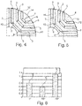
- a rotor 1 of a rotating electrical machine comprising a rotor mass 2 in which housings 3 are formed so as to define the poles 4 of the rotor, each pole having a radial axis X.
- the rotor has nine housings per pole, which are arranged in three concentric rows 6 around each of the poles, the concavity of the rows being oriented towards the air gap.
- a row 6 has three housings 3 arranged consecutively in the row.
- the three rows 6 of the same pole are of decreasing length when moving in the direction of the air gap, the longest being located on the side of the axis of rotation and the shortest on the side of the air gap.
- the housings 3 are elongated, extending each along a longitudinal axis Y which forms an angle ⁇ with the radial axis X of the pole. They each have two short sides 9, the respective short sides 9 of two consecutive housings 3 of the same row 6 defining between them a material bridge 10.
- the material bridge 10 generally extends along a longitudinal axis Z of the bridge oriented towards the radial axis X of the corresponding pole of the rotor 1 when moving away from the axis of rotation.
- the longitudinal axis Z of the material bridge 10 is rectilinear and forms with the radial axis X of the corresponding pole of the rotor an angle ⁇ of a non-zero value greater than 5 °, which is in this example of the order of d 'about 15 °.
- the short sides 9 of a housing are oriented in the direction of the radial axis X of the pole when moving in the direction of the air gap.
- the housings 3 are generally trapezoidal in shape, and have two long sides 14, one of the long sides being smaller than the other, the shorter of the long sides being closer to the air gap than the longer of the long sides .
- the rotor 1 has twice as many bridges of material as there are rows of housings, each row 6 comprising three housings 3 and two bridges of material 10.
- the number of bridges of material 10 in a pole 4 is equal to the number of housings in the pole, from which is subtracted the number of rows 6 in said pole.
- Each row 6 has a central housing 3a and two side housings 3b. The arrangement of the housings and the material bridges in a row is symmetrical about the radial axis X of the pole.
- the side housings are separated from the air gap by tangential bridges 12.
- the coefficient A corresponding to the configuration of the figure 2 is compared to the coefficients B and C of the configurations of figures 4 and 5 , for which the angle ⁇ is respectively zero, the axes of the material bridges 10 being parallel to the radial axis X of the pole, and of 15 ° in the opposite direction, the axes of the material bridges 10 being oriented away from the radial axis X of the corresponding pole of the rotor 1 when moving in the direction of the air gap 11. It can be seen that the fatigue safety coefficient is maximum for the configuration according to the invention, where the Z axis is oriented towards the X axis of the corresponding pole when approaching the air gap.
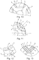
- the rotor 1 may include permanent magnets 11 inserted in each of the housings, the magnets not being shown in the figure. figure 1 but visible on the figure 7 , their direction of magnetization being illustrated by arrows.
- the permanent magnets are in this example of generally rectangular shape in cross section. The placement of the magnets in the housings can leave a free space 15 in each housing between the magnet and the short sides of the corresponding housing. The free space can be generally triangular in shape, as illustrated.
- some of the housings may be without a magnet.
- the housings of one of the rows are arranged in a central branch and two side branches, the central branch being the only one to include a permanent magnet, the side housings not including a permanent magnet. In the example of figure 7a , it's the contrary.
- the central housings of a row may have a length L greater than that of the lateral housings of said row, thus the lateral branches of the U are shorter than the central branch. It is also the opposite in the example of figure 7a .
- the figures 7 and 7a also differ from the figure 1 in that the bridges of material 10 of the different rows have a variable width l , decreasing as one approaches the air gap 13.
- the longitudinal axes of two bridges of material of two different rows are parallel to each other and offset by a non-zero distance d , for example about 1.5 mm, this offset taking place away from the radial axis when moving away from the axis of rotation.
- the distance d is measured perpendicular to said longitudinal Z axes.
- the Z axes of the bridges have been illustrated on figure 8 , and the shift of them at the figure 9 .
- the shift of the longitudinal axes of the bridges can be done as a variant towards the radial axis of the pole when one moves away from the axis of rotation, in other words the shift is done in the direction of the radial axis of the pole when l 'we are approaching the top of the pole.
- the longitudinal axes of two bridges of material from two different rows are mutually parallel and coincident, when one is on the same side of the X axis.
- the rotor may have a single row of housings per pole, as illustrated by way of example not forming part of the invention on figure 10 .
- the housings can each extend along a longitudinal axis which can be rectilinear, as illustrated above, or curved, as illustrated in figure 11 .
- the short sides of a housing can be straight, as shown above, or curved, as shown in figure 12 .
- All the rows can have the same number of slots, as described above. It is not beyond the scope of the present invention if it is otherwise.
- figure 13 an example in which two rows of the same pole have a different number of dwellings.
- a row of housings has two, namely the row closest to the air gap, and the other rows have three housings.
- the row closest to the air gap has two housings arranged in a V.
- the bridge 10 is thus central.
- the other two rows each comprise three housings arranged in a flared U-shape, each with two bridges of material 10 symmetrical with respect to the radial axis X of the pole.
- the rotor can cooperate with any type of stator, with distributed or concentrated winding.
Landscapes
- Engineering & Computer Science (AREA)
- Power Engineering (AREA)
- Permanent Field Magnets Of Synchronous Machinery (AREA)
- Iron Core Of Rotating Electric Machines (AREA)
Description
- La présente invention concerne les machines électriques tournantes et notamment celles comportant un rotor à concentration de flux, et plus particulièrement les rotors de telles machines.
- On connaît des machines électriques tournantes comportant un rotor qui comporte des aimants disposés dans des logements de manière à définir des pôles du rotor. Les logements peuvent être en forme d'arc de cercle ou de V. Ils sont séparés de l'entrefer par des ponts de matière orientés circonférentiellement, qui permettent de maintenir la cohésion du rotor contre les efforts mécaniques que subit la machine.
- De telles machines sont connues par exemple par les
brevets EP 0746079 ,US 6 121 706 ,US 6 630 762 ,US 7 779 153 , ainsi que par les demandesEP 1 763 121 ,US 2002/0175584 etWO 2008/123086 . - On connaît également par la demande
WO 2007/055775 une machine électrique comportant au rotor des logements ayant des petits côtés en forme de demi-cercle. - Par ailleurs, la demande
EP 1 276 204 porte sur un moteur à aimants permanents dans lequel les aimants permanents sont disposés en une rangée unique. - Afin d'améliorer la cohésion de la machine à l'encontre des efforts centrifuges, il est également connu de ménager des ponts radiaux entre les logements. Ces ponts sont, par exemple comme dans le
brevet US 6 630 762 , disposés le long d'un axe radial du pôle correspondant. - Afin d'optimiser la distribution du flux magnétique dans le rotor, on cherche à limiter la taille des ponts radiaux afin de minimiser le passage du flux magnétique dans ces ponts et les pertes de flux dans le pôle.
- En revanche, il est nécessaire que ces ponts radiaux aient une épaisseur suffisante pour éviter leur rupture, le rotor étant très fortement sollicité par les forces centrifuges.
- Ces exigences contradictoires rendent difficile la conception du rotor.
- Il existe donc un besoin pour disposer d'un rotor suffisamment solide pour résister aux efforts centrifuges tout en permettant une bonne circulation du flux et une bonne concentration de ce dernier dans les pôles.
- L'invention vise à répondre à ce besoin et a ainsi pour objet, selon un premier de ses aspects suivant la revendication 1, un rotor de machine électrique tournante comportant une masse rotorique dans laquelle sont ménagés des logements de manière à définir les pôles du rotor, chaque pôle ayant un axe radial du pôle, les logements étant de forme allongée et comportant chacun deux petits côtés, les logements étant disposés en plusieurs rangées par pôle, une rangée comportant au moins trois logements disposés consécutivement, leurs petits côtés définissant entre deux logements consécutifs d'une même rangée un pont de matière, ce pont de matière s'étendant généralement selon un axe longitudinal du pont orienté obliquement en rapprochement de l'axe radial du pôle correspondant du rotor, lorsque l'on se déplace en s'éloignant de l'axe de rotation.
- Le rotor selon l'invention permet de concilier les exigences contradictoires précitées, c'est-à-dire d'une part la circulation du flux dans le circuit magnétique, et d'autre part la tenue mécanique du rotor. Les ponts de matière orientés obliquement mentionnés ci-dessus permettent de supporter les efforts centrifuges auxquels peut être soumis le rotor, sans pénaliser la machine sur le plan magnétique.
- Ainsi, grâce à l'invention, on peut réduire la largeur du pont pour la même vitesse de rotation et obtenir une meilleure concentration du flux magnétique dans le pôle correspondant. On peut réduire les contraintes dans les ponts en équilibrant mieux les efforts de flexion, et n'obtenir sensiblement que des contraintes de traction dans ces ponts. On peut également, avec une même largeur de pont, être en mesure de faire fonctionner la machine à une vitesse de rotation plus élevée et obtenir une meilleure concentration du flux magnétique dans les pôles.
- Le rotor comporte des aimants permanents insérés dans tous les logements.
- Les aimants permanents peuvent être réalisés en ferrites ou avec des terres rares ou avec tout autre type de matériau magnétique. La disposition des logements permet de concentrer le flux des aimants et d'obtenir avec des aimants en ferrites des performances intéressantes. Dans un exemple de réalisation, les logements d'une même rangée sont disposés selon une branche centrale et deux branches latérales situées de part et d'autre de la branche centrale, donnant par exemple une configuration en U, la branche centrale étant par exemple seule à comporter un ou plusieurs aimants permanents, les branches latérales ne logeant pas d'aimant permanent.
- Par « axe radial du pôle », on entend un axe du pôle orienté radialement, c'est-à-dire selon un rayon du rotor. Il peut s'agir d'un axe de symétrie pour le pôle. Cet axe radial peut intersecter le sommet du pôle.
- Les ponts de matière formés entre les logements s'étendent obliquement généralement selon un axe longitudinal du pont qui forme avec l'axe radial du pôle correspondant du rotor un angle d'une valeur non nulle et supérieure à 5°. mieux supérieure à 10°. par exemple de l'ordre d'environ 15°. L'angle est inférieur à 45°, mieux inférieur à 30°, voire inférieur à 20°.
- Par « axe longitudinal du pont » on désigne l'axe disposé de manière centrale par rapport aux deux petits côtés des logements adjacents définissant ce pont de matière. Cet axe est de préférence rectiligne.
- La concavité de la rangée peut être orientée vers le sommet du pôle, c'est à dire vers l'entrefer. Pour un même pôle, les logements de ce pôle sont disposés en plusieurs rangées, chacune de concavité qui peut être orientée vers le sommet du pôle, notamment en rangées sensiblement concentriques. Par « concentriques », on entend que des axes médians des logements des rangées, pris dans un plan perpendiculaire à l'axe de rotation du rotor, se coupent en un même point. Cette disposition en plusieurs rangées concentriques permet d'améliorer la concentration du flux sans nécessairement avoir à augmenter la taille des logements ou la quantité d'aimants permanents nécessaires pour obtenir un flux équivalent. Le nombre de rangées par pôle peut notamment être de deux, trois ou quatre.
- Lorsque le rotor comporte pour un même pôle plusieurs rangées, ces dernières peuvent être de longueur décroissante lorsque l'on se déplace en direction de l'entrefer, la plus longue étant plus proche de l'axe de rotation et la plus courte du côté de l'entrefer. La longueur d'une rangée correspond à la longueur cumulée des logements de cette rangée.
- Au moins, deux logements de deux rangées d'un même pôle peuvent s'étendre parallèlement l'un à l'autre. Tous les logements d'une rangée peuvent s'étendre parallèlement aux logements correspondants d'une autre rangée.
- Le rotor peut comporter autant de ponts de matière orientés obliquement que de rangées de logements, voire jusqu'à deux fois plus, ou même trois fois plus. Le nombre de ponts de matière orientés obliquement dans un pôle peut être égal au nombre de logements dans le pôle, auquel on soustrait le nombre de rangées dans ledit pôle.
- Une rangée comporte au moins trois logements. Une rangée peut par exemple comporter un logement central et deux logements latéraux. Au moins une rangée peut comporter un nombre impair de logements, par exemple au moins trois logements.
- Deux rangées d'un même pôle peuvent avoir un nombre de logements différent. Dans un exemple de réalisation de l'invention, au moins un pôle comporte une rangée de logements comportant un nombre inférieur de logements à ceux d'une autre rangée de ce pôle, par exemple deux contre trois pour l'autre rangée. La rangée ayant le plus faible nombre de logements est de préférence la plus proche de l'entrefer et la plus éloignée de l'axe de rotation.
- La disposition des logements et/ou des ponts de matière dans une rangée est de préférence symétrique par rapport à l'axe radial du pôle.
- Dans une rangée, les logements peuvent être disposés en V ou en U, le U pouvant avoir une forme évasée vers l'entrefer. Autrement dit, les logements constituant les branches latérales du U peuvent être non parallèles entre eux. Ainsi, l'inclinaison des ponts radiaux peut être opposée à celle des logements latéraux, par rapport à l'axe radial du pôle.
- Lorsque les logements d'une même rangée sont disposés selon un arrangement en forme de U, le logement central peut être de longueur supérieure ou inférieure à celle d'une branche du U. Dans un exemple de réalisation, les branches du U sont plus courtes que la branche centrale constituant le fond du U.
- Les logements peuvent s'étendre chacun, lorsqu'observés en section dans un plan perpendiculaire à l'axe de rotation du rotor, selon un axe longitudinal qui peut être rectiligne ou courbe.
- Les logements peuvent avoir une largeur constante ou variable lorsque l'on se déplace le long de leur axe longitudinal, dans un plan perpendiculaire à l'axe de rotation du rotor.
- Les petits côtés d'un logement sont orientés en direction de l'axe radial du pôle lorsque l'on se déplace en éloignement de l'axe de rotation, et convergent par exemple sensiblement vers le sommet du pôle.
- Les logements peuvent avoir, en section transversale, c'est-à-dire perpendiculairement à l'axe de rotation, une forme générale rectangulaire ou trapézoïdale, cette liste n'étant pas limitative.
- Les petits côtés d'un logement peuvent être perpendiculaires aux grands côtés du logement. Les petits côtés d'un logement peuvent être inclinés par rapport aux grands côtés du logement.
- Au moins un logement peut avoir deux grands côtés, l'un des grands côtés étant plus petit que l'autre. Dans ce cas, par exemple lorsque le logement est de forme générale trapézoïdale, le plus court des grands côtés peut être situé plus près de l'entrefer que le plus long des grands côtés.
- Les petits côtés d'un logement sont rectilignes. Les ponts de matière entre deux logements consécutifs d'une rangée peuvent avoir une largeur, mesurée perpendiculairement à leur axe longitudinal, inférieure à 8 mm et les ponts de matière peuvent avoir une largeur supérieure à 0,5 mm.
- Les aimants permanents peuvent être de forme générale rectangulaire. Compte-tenu de la forme des logements, la mise en place des aimants dans les logements peut laisser un espace libre dans le logement entre les aimants et les petits côtés du logement correspondant. L'espace libre est par exemple de forme générale triangulaire.
- Selon l'invention, les axes longitudinaux de deux ponts de matière de deux rangées différentes d'un même pôle sont parallèles entre eux.
- Ils sont décalés d'une distance d comprise entre 0 (valeur exclue) et 10 mm. La distance d est mesurée perpendiculairement auxdits axes longitudinaux. Cette distance d est inférieure à la plus grande largeur des ponts de matière correspondants. Un tel décalage permet de compenser les flexions introduites par les forces centrifuges.
- L'invention a pour objet un rotor de machine électrique tournante comportant une masse rotorique dans laquelle sont ménagés des logements de manière à définir les pôles du rotor, chaque pôle ayant un axe radial du pôle,
les logements étant de forme allongée et comportant chacun deux petits côtés, les logements étant disposés pour chaque pôle en plusieurs rangées par pôle, dont la concavité peut être orientée vers l'entrefer, une rangée comportant au moins trois logements disposés consécutivement, leurs petits côtés définissant entre deux logements consécutifs d'une même rangée un pont de matière,
ce pont de matière s'étendant généralement selon un axe longitudinal du pont, les axes longitudinaux de deux ponts de matière appartenant à deux rangées différentes étant parallèles entre eux et décalés d'une distance d comprise entre 0 (valeur exclue) et 10 mm. Suivant un exemple ne faisant pas partie de l'invention, les axes longitudinaux de ces deux ponts de matière sont non parallèles entre eux. Ils peuvent former avec l'axe radial du pôle un angle qui varie, par exemple qui augmente lorsque l'on se rapproche de l'axe de rotation. - Il est particulièrement avantageux de procéder à un décalage des axes longitudinaux des ponts de matière, notamment lorsque les logements d'une rangée sont disposés en U et que les branches latérales de chaque U sont plus courtes que la branche centrale, ou en variante lorsque la branche centrale est la seule à comporter un aimant permanent et que les logements correspondant aux branches latérales ne comportent pas d'aimant permanent.
- Le décalage des axes longitudinaux des ponts peut se faire dans ce cas vers l'axe radial du pôle lorsque l'on se rapproche de l'axe de rotation, autrement dit le décalage se fait du côté opposé de l'axe radial du pôle lorsque l'on se rapproche du sommet du pôle.
- Le décalage des axes longitudinaux des ponts peut se faire en variante vers l'axe radial du pôle lorsqu'on s'éloigne de l'axe de rotation, autrement dit le décalage se fait en direction de l'axe radial du pôle lorsque l'on se rapproche du sommet du pôle.
- Il est particulièrement avantageux de procéder à un tel décalage des axes longitudinaux des ponts de matière, notamment lorsque les logements d'une rangée sont disposés en U et que les branches latérales de chaque U sont plus longues que la branche centrale, ou en variante lorsque les branches latérales sont les seules à comporter un aimant permanent et que les logements correspondant à la branche centrale ne comportent pas d'aimant permanent.
- Le décalage est inférieur à
la plus grande largeur des ponts. - La masse rotorique peut être formée d'un empilement de tôles ou d'une ou plusieurs tôle(s) individuelle(s) enroulée(s) sur elle(s)-même(s) autour de l'axe de rotation. Chaque couche de tôle de la masse rotorique peut être d'un seul tenant. Le rotor peut être dépourvu de pièces polaires individuelles.
- Le rotor peut comporter un nombre de pôles compris entre 2 et 12, mieux entre 4 et 8.
- L'invention a encore pour objet, selon un autre de ses aspects, une machine électrique tournante comportant un rotor tel que décrit plus haut. La machine peut être à reluctance. Elle peut constituer un moteur synchrone.
- La machine peut fonctionner à une vitesse périphérique nominale (vitesse tangentielle prise au diamètre extérieur du rotor) qui peut être supérieure ou égale à 100 mètres par seconde, la machine selon l'invention permettant un fonctionnement à des vitesses importantes si cela est souhaité.
- La machine peut avoir une taille relativement élevée. Le diamètre du rotor peut être supérieur à 50 mm, mieux supérieur à 80 mm, étant par exemple compris entre 80 et 300 mm.
- L'invention pourra être mieux comprise à la lecture de la description détaillée qui va suivre, d'exemples de réalisation non limitatifs de celle-ci, et l'examen du dessin annexé, sur lequel :
- la
figure 1 est une vue schématique et partielle d'un rotor, - la
figure 2 en représente un détail de réalisation, - la
figure 3 est une vue schématique et partielle faisant apparaître l'axe longitudinal d'un pont de matière, - les
figures 4 et 5 sont des vues analogues à lafigure 2 de variantes de réalisation, - la
figure 6 illustre le coefficient de sécurité en fatigue pour les configurations desfigures 2 ,4 et 5 , - les
figures 7 et 7a sont des vues analogues à lafigure 2 de variantes de réalisation, la direction d'aimantation des aimants étant matérialisée par une flèche, - la
figure 8 est une vue schématique et partielle illustrant le décalage entre les axes longitudinaux des ponts de matière, - la
figure 9 en est une vue de détail selon IX, et - les
figures 10 à 13 sont des exemples ne faisant pas partie de l'invention. - On a illustré aux
figures 1 à 3 un rotor 1 de machine électrique tournante, comportant une masse rotorique 2 dans laquelle sont ménagés des logements 3 de manière à définir les pôles 4 du rotor, chaque pôle ayant un axe radial X. - Dans cet exemple, le rotor comporte neuf logements par pôle, qui sont disposés en trois rangées concentriques 6 autour de chacun des pôles, la concavité des rangées étant orientée vers l'entrefer. Une rangée 6 comporte trois logements 3 disposés consécutivement dans la rangée. Les trois rangées 6 d'un même pôle sont de longueur décroissante lorsque l'on se déplace en direction de l'entrefer, la plus longue étant située du côté de l'axe de rotation et la plus courte du côté de l'entrefer.
- Les logements 3 sont de forme allongée, s'étendant chacun selon un axe longitudinal Y qui forme un angle γ avec l'axe radial X du pôle. Ils comportent chacun deux petits côtés 9, les petits côtés respectifs 9 de deux logements consécutifs 3 d'une même rangée 6 définissant entre eux un pont de matière 10.
- Le pont de matière 10 s'étend généralement selon un axe longitudinal Z du pont orienté en rapprochement de l'axe radial X du pôle correspondant du rotor 1 lorsque l'on s'éloigne de l'axe de rotation. L'axe longitudinal Z du pont de matière 10 est rectiligne et forme avec l'axe radial X du pôle correspondant du rotor un angle α d'une valeur non nulle et supérieure à 5°, qui est dans cet exemple de l'ordre d'environ 15°.
- Les petits côtés 9 d'un logement sont orientés en direction de l'axe radial X du pôle lorsque l'on se déplace en direction de l'entrefer. Les logements 3 sont de forme générale trapézoïdale, et ont deux grands côtés 14, l'un des grands côtés étant plus petit que l'autre, le plus court des grands côtés étant plus près de l'entrefer que le plus long des grands côtés.
- Le rotor 1 comporte deux fois plus de ponts de matière que de rangées de logements, chaque rangée 6 comportant trois logements 3 et deux ponts de matière 10. Le nombre de ponts de matière 10 dans un pôle 4 est égal au nombre de logements dans le pôle, auquel on soustrait le nombre de rangées 6 dans ledit pôle. Chaque rangée 6 comporte un logement central 3a et deux logements latéraux 3b. La disposition des logements et des ponts de matière dans une rangée est symétrique par rapport à l'axe radial X du pôle.
- Les logements latéraux sont séparés de l'entrefer par des ponts tangentiels 12.
- Ces ponts tangentiels ne reprennent qu'une partie assez faible des efforts centrifuges, tandis que les ponts 10 qui séparent deux logements doivent supporter l'essentiel de la charge des efforts centrifuges.
- Pour faire apparaître les avantages de l'invention en termes de sécurité en fatigue, on a illustré à la
figure 6 le coefficient de sécurité en fatigue qui traduit l'effort centrifuge que peut supporter le rotor, lorsqu'il est infiniment répété, en fonction de l'angle α. Il évolue en raison inverse de la contrainte au point le plus sollicité dans la structure. Le coefficient A correspondant à la configuration de lafigure 2 est comparé aux coefficients B et C des configurations desfigures 4 et 5 , pour lesquels l'angle α est respectivement nul, les axes des ponts de matière 10 étant parallèles à l'axe radial X du pôle, et de 15° dans le sens opposé, les axes des ponts de matière 10 étant orientés en éloignement de l'axe radial X du pôle correspondant du rotor 1 lorsque l'on se déplace en direction de l'entrefer 11. On voit que le coefficient de sécurité en fatigue est maximum pour la configuration selon l'invention, où l'axe Z est orienté en rapprochement de l'axe X du pôle correspondant lorsque l'on se rapproche de l'entrefer. - Le rotor 1 peut comporter des aimants permanents 11 insérés dans chacun des logements, les aimants n'étant pas représentés sur la
figure 1 mais visibles sur lafigure 7 , leur direction d'aimantation étant illustrée par des flèches. Les aimants permanents sont dans cet exemple de forme générale rectangulaire en section transversale. La mise en place des aimants dans les logements peut laisser un espace libre 15 dans chaque logement entre l'aimant et les petits côtés du logement correspondant. L'espace libre peut être de forme générale triangulaire, comme illustré. - Dans une variante ne faisant pas partie de l'invention, certains des logements peuvent être dépourvus d'aimant. Dans l'exemple de réalisation illustré à la
figure 7 , les logements de l'une des rangées sont disposés en une branche centrale et deux branches latérales, la branche centrale étant seule à comporter un aimant permanent, les logements latéraux ne comportant pas d'aimant permanent. Dans l'exemple de lafigure 7a , c'est le contraire. - En outre, on voit sur la
figure 7 que les logements centraux d'une rangée peuvent avoir une longueur L supérieure à celle des logements latéraux de ladite rangée, ainsi les branches latérales du U sont plus courtes que la branche centrale. C'est également le contraire dans l'exemple de lafigure 7a . - Les
figures 7 et 7a diffèrent également de lafigure 1 par le fait que les ponts de matière 10 des différentes rangées y ont une largeur l variable, allant en diminuant lorsque l'on se rapproche de l'entrefer 13. - En outre, sur la
figure 7 , les axes longitudinaux de deux ponts de matière de deux rangées différentes sont parallèles entre eux et décalés d'une distance d non nulle, par exemple d'environ 1,5 mm, ce décalage ayant lieu en s'éloignant de l'axe radial lorsque l'on s'éloigne de l'axe de rotation. La distance d est mesurée perpendiculairement auxdits axes longitudinaux Z. Les axes Z des ponts ont été illustrés à lafigure 8 , et le décalage d entre eux à lafigure 9 . - Dans le mode de réalisation de la
figure 7a , le décalage des axes longitudinaux des ponts peut se faire en variante vers l'axe radial du pôle lorsqu'on s'éloigne de l'axe de rotation, autrement dit le décalage se fait en direction de l'axe radial du pôle lorsque l'on se rapproche du sommet du pôle. Dans l'exemple de lafigure 1 , les axes longitudinaux de deux ponts de matière de deux rangées différentes sont parallèles entre eux et confondus, lorsque l'on est d'un même côté de l'axe X. - Le rotor peut comporter une seule rangée de logements par pôle, comme illustré à titre d'exemple ne faisant pas partie de l'invention à la
figure 10 . - Les logements peuvent s'étendre chacun selon un axe longitudinal qui peut être rectiligne, comme illustré précédemment, ou courbe, comme illustré à la
figure 11 . - Les petits côtés d'un logement peuvent être rectilignes, comme illustré précédemment, ou courbes, comme illustré à la
figure 12 . - Toutes les rangées peuvent comporter le même nombre de logements, comme décrit précédemment. On ne sort pas du cadre de la présente invention s'il en est autrement. A titre d'exemple on a illustré à la
figure 13 un exemple dans lequel deux rangées d'un même pôle ont un nombre de logements différent. Par exemple, comme illustré, une rangée de logements en comporte deux, à savoir la rangée la plus proche de l'entrefer, et les autres rangées comportent trois logements. - De plus, la rangée la plus proche de l'entrefer comporte deux logements disposés en V. Dans cette rangée, le pont 10 est ainsi central. Les deux autres rangées comportent chacune trois logements disposés en U évasé, avec chacune deux ponts de matière 10 symétriques par rapport à l'axe radial X du pôle.
- L'invention n'est pas limitée aux exemples illustrés. On peut notamment modifier la polarité du rotor sans sortir du cadre de la présente invention.
- Le rotor peut coopérer avec tout type de stator, à bobinage distribué ou concentré.
- L'expression « comportant un » doit être comprise comme étant synonyme de « comportant au moins un ».
Claims (14)
- Rotor (1) de machine électrique tournante, comportant une masse rotorique (2) dans laquelle sont ménagés des logements (3) de manière à définir les pôles (4) du rotor, chaque pôle ayant un axe radial (X) du pôle,
les logements (3) étant de forme allongée et comportant chacun deux petits côtés (9), les logements étant disposés en plusieurs rangées (6) par pôle, les logements dans une rangée étant disposés en U, le U pouvant avoir une forme évasée vers l'entrefer,
une rangée (6) comportant au moins trois logements (3) disposés consécutivement, leurs petits côtés (9) définissant entre deux logements consécutifs d'une même rangée un pont de matière (10),
ce pont de matière (10) s'étendant généralement selon un axe longitudinal (Z) du pont orienté en rapprochement de l'axe radial (X) du pôle correspondant du rotor, lorsque l'on s'éloigne de l'axe de rotation,
caractérisé en ce que les petits côtés d'un logement sont rectilignes, les axes longitudinaux de deux ponts de matière de deux rangées différentes d'un même pôle étant parallèles entre eux et décalés d'une distance (d) comprise entre 0 (valeur exclue) et 10 mm,
le décalage étant inférieur à la plus grande largeur des ponts,
les ponts de matière des différentes rangées ont une largeur variable, allant en diminuant lorsque l'on se rapproche de l'entrefer,
les ponts de matière s'étendant obliquement généralement selon un axe longitudinal du pont qui forme avec l'axe radial du pôle correspondant du rotor un angle d'une valeur supérieure à 5° et inférieure à 45°,
le rotor comportant des aimants permanents insérés dans chacun des logements. - Rotor selon la revendication précédente, dans lequel :a) (i) les branches latérales de chaque U sont plus courtes que la branche centrale ou (ii) la branche centrale est la seule à comporter un aimant permanent et les logements correspondant aux branches latérales ne comportent pas d'aimant permanent, etb) le décalage des axes longitudinaux des ponts se fait vers l'axe radial du pôle lorsque l'on se rapproche de l'axe de rotation.
- Rotor selon la revendication 1, dans lequel :a) (i) les branches latérales de chaque U sont plus longues que la branche centrale ou (ii) les branches latérales sont les seules à comporter un aimant permanent et les logements correspondant à la branche centrale ne comporte pas d'aimant permanent, etb) le décalage des axes longitudinaux des ponts se fait vers l'axe radial du pôle lorsque l'on s'éloigne de l'axe de rotation.
- Rotor selon l'une quelconque des revendications précédentes, les petits côtés d'un logement étant rectilignes, dans lequel le pont de matière (10) s'étend généralement selon un axe longitudinal (Z) du pont qui forme avec un axe radial (X) du pôle correspondant du rotor un angle (α) d'une valeur inférieure à 30°.
- Rotor selon l'une quelconque des revendications précédentes, dans lequel le pont de matière (10) s'étend généralement selon un axe longitudinal (2) du pont qui forme avec un axe radial (X) du pôle correspondant du rotor un angle (α) d'une valeur non nulle et supérieure à 10°.
- Rotor selon l'une quelconque des revendications précédentes, au moins une rangée (4) comportant un nombre impair de logements (3), notamment au moins trois logements.
- Rotor selon l'une quelconque des revendications précédentes, dans lequel, lorsque le rotor (1) comporte pour un même pôle (4) plusieurs rangées (6), ces dernières sont de longueur décroissante lorsque l'on se déplace en direction de l'entrefer.
- Rotor selon l'une quelconque des revendications précédentes, la disposition des logements (3) et/ou des ponts de matière (10) dans une rangée étant symétrique par rapport à l'axe radial (X) du pôle.
- Rotor selon l'une quelconque des revendications précédentes, le pont de matière (10) ayant une largeur (l), mesurée perpendiculairement à son axe longitudinal, inférieure à 8 mm, et pouvant être notamment supérieure à 0.5 mm.
- Rotor selon l'une quelconque des revendications précédentes, les axes longitudinaux (Z) de deux ponts de matière (10) de deux rangées différentes (6) étant parallèles entre eux.
- Rotor selon l'une quelconque des revendications précédentes, dans lequel les logements (3) sont de forme générale trapézoïdale, le plus court des grands côtés (14) du logement étant plus près de l'entrefer que le plus long des grands côtés.
- Rotor selon l'une quelconque des revendications précédentes, le nombre de ponts (10) orientés obliquement dans un pôle (4) étant égal au nombre de logements dans le pôle, auquel on soustrait le nombre de rangées dans ledit pôle.
- Rotor selon l'une quelconque des revendications précédentes, la masse rotorique (2) étant formée d'un empilement de couches de tôle, chaque couche de tôle de la masse rotorique étant d'un seul tenant.
- Machine électrique tournante comportant un rotor (1) selon l'une quelconque des revendications précédentes.
Priority Applications (1)
| Application Number | Priority Date | Filing Date | Title |
|---|---|---|---|
| EP17167976.4A EP3288156A1 (fr) | 2012-09-13 | 2013-09-12 | Machine électrique |
Applications Claiming Priority (2)
| Application Number | Priority Date | Filing Date | Title |
|---|---|---|---|
| FR1258587A FR2995469B1 (fr) | 2012-09-13 | 2012-09-13 | Rotor de machine electrique tournante, comportant une masse rotorique dans laquelle sont menages des logements. |
| PCT/IB2013/058500 WO2014041507A1 (fr) | 2012-09-13 | 2013-09-12 | Rotor de machine electrique tournante, comportant une masse rotorique dans laquelle sont menages des logements |
Related Child Applications (2)
| Application Number | Title | Priority Date | Filing Date |
|---|---|---|---|
| EP17167976.4A Division-Into EP3288156A1 (fr) | 2012-09-13 | 2013-09-12 | Machine électrique |
| EP17167976.4A Division EP3288156A1 (fr) | 2012-09-13 | 2013-09-12 | Machine électrique |
Publications (3)
| Publication Number | Publication Date |
|---|---|
| EP2896114A1 EP2896114A1 (fr) | 2015-07-22 |
| EP2896114B1 EP2896114B1 (fr) | 2017-07-05 |
| EP2896114B2 true EP2896114B2 (fr) | 2020-11-25 |
Family
ID=48050817
Family Applications (2)
| Application Number | Title | Priority Date | Filing Date |
|---|---|---|---|
| EP17167976.4A Withdrawn EP3288156A1 (fr) | 2012-09-13 | 2013-09-12 | Machine électrique |
| EP13795859.1A Active EP2896114B2 (fr) | 2012-09-13 | 2013-09-12 | Rotor de machine électrique tournante, comportant une masse rotorique dans laquelle sont ménagés des logements |
Family Applications Before (1)
| Application Number | Title | Priority Date | Filing Date |
|---|---|---|---|
| EP17167976.4A Withdrawn EP3288156A1 (fr) | 2012-09-13 | 2013-09-12 | Machine électrique |
Country Status (6)
| Country | Link |
|---|---|
| US (1) | US10491063B2 (fr) |
| EP (2) | EP3288156A1 (fr) |
| CN (1) | CN104620473B (fr) |
| BR (1) | BR112015005561A2 (fr) |
| FR (1) | FR2995469B1 (fr) |
| WO (1) | WO2014041507A1 (fr) |
Families Citing this family (27)
| Publication number | Priority date | Publication date | Assignee | Title |
|---|---|---|---|---|
| JP5866074B1 (ja) | 2014-03-05 | 2016-02-17 | 三菱電機株式会社 | シンクロナスリラクタンスモータ |
| JP2015186383A (ja) * | 2014-03-25 | 2015-10-22 | アイシン・エィ・ダブリュ株式会社 | 回転電機のロータ |
| JP6366986B2 (ja) * | 2014-04-11 | 2018-08-01 | 株式会社東芝 | 同期リラクタンス型回転電機 |
| WO2016024325A1 (fr) * | 2014-08-11 | 2016-02-18 | 富士電機株式会社 | Machine dynamoélectrique |
| WO2016024324A1 (fr) * | 2014-08-11 | 2016-02-18 | 富士電機株式会社 | Machine dynamo-électrique |
| ITUB20150608A1 (it) * | 2015-04-14 | 2016-10-14 | Ge Avio Srl | Metodo di realizzazione di una struttura di rotore di una macchina elettrica sincrona a riluttanza, e relativa macchina elettrica sincrona a riluttanza |
| FR3035552B1 (fr) * | 2015-04-23 | 2019-05-24 | IFP Energies Nouvelles | Machine electrique et procede pour l'equilibrage dynamique du rotor de cette machine electrique. |
| JP6451517B2 (ja) * | 2015-06-10 | 2019-01-16 | 株式会社デンソー | ロータ |
| ITUA20162566A1 (it) * | 2016-04-13 | 2017-10-13 | S M E S P A | Rotore per una macchina sincrona e macchina sincrona comprendente tale rotore |
| JP6747064B2 (ja) * | 2016-06-02 | 2020-08-26 | 株式会社明電舎 | 永久磁石式回転電機 |
| CN106329773B (zh) * | 2016-08-31 | 2018-11-27 | 恒大法拉第未来智能汽车(广东)有限公司 | 电机的转子、电机及车辆 |
| EP3560073A1 (fr) * | 2016-12-21 | 2019-10-30 | ABB Schweiz AG | Rotor pour machines électriques tournantes |
| JP6813032B2 (ja) | 2017-01-12 | 2021-01-13 | アイシン・エィ・ダブリュ株式会社 | 回転電機用ロータ |
| US10715017B2 (en) * | 2017-06-02 | 2020-07-14 | Hamilton Sundstrand Corporation | Hybrid synchronous machines |
| CN107394922B (zh) * | 2017-08-24 | 2023-11-14 | 智车优行科技(上海)有限公司 | 内置式永磁电机转子和永磁电机 |
| FR3071370B1 (fr) * | 2017-09-18 | 2019-09-13 | IFP Energies Nouvelles | Isthmes de ponts magnetiques d'un rotor de machine electrique |
| CN108777520B (zh) * | 2018-07-17 | 2020-03-27 | 珠海格力电器股份有限公司 | 一种交替极电机 |
| FR3084534B1 (fr) * | 2018-07-24 | 2020-07-17 | IFP Energies Nouvelles | Rotor de machine electrique avec ponts magnetiques asymetriques |
| CN109067039A (zh) * | 2018-09-12 | 2018-12-21 | 南京航空航天大学 | 一种非对称蝴蝶型内置式永磁同步电机 |
| FR3094583B1 (fr) * | 2019-03-29 | 2021-03-12 | Ifp Energies Now | Rotor de machine électrique avec pôles asymétriques et aimants latéraux |
| WO2021162771A1 (fr) * | 2020-02-14 | 2021-08-19 | Gentiam Llc | Machine d'excitation à rotors intérieurs multiples à grande vitesse |
| CN115380453A (zh) * | 2020-04-15 | 2022-11-22 | 松下知识产权经营株式会社 | 转子和电动机 |
| FR3120168B1 (fr) * | 2021-02-22 | 2025-02-21 | Nidec Psa Emotors | Rotor de machine électrique tournante |
| FR3121294B1 (fr) * | 2021-03-29 | 2024-07-12 | Nidec Psa Emotors | Rotor de machine électrique tournante |
| IT202100028502A1 (it) * | 2021-11-10 | 2023-05-10 | Eldor Corp Spa | Motore elettrico |
| JP7773957B2 (ja) * | 2022-09-26 | 2025-11-20 | 株式会社日立インダストリアルプロダクツ | 回転電機、並びに電動車両 |
| DE102024108047A1 (de) * | 2024-03-21 | 2025-09-25 | Schaeffler Technologies AG & Co. KG | Permanentmagneterregter Rotor und elektrische Maschine |
Citations (5)
| Publication number | Priority date | Publication date | Assignee | Title |
|---|---|---|---|---|
| JP2003158838A (ja) † | 2001-11-20 | 2003-05-30 | Aisin Seiki Co Ltd | 永久磁石型同期機 |
| WO2007055775A2 (fr) † | 2005-10-31 | 2007-05-18 | Caterpillar Inc. | Machine electrique rotative |
| US7498708B2 (en) † | 2004-10-26 | 2009-03-03 | Kollmorgen Corporation | Design of the magnet and webs in interior permanent magnet rotors |
| US20090224624A1 (en) † | 2008-03-06 | 2009-09-10 | Ajith Kuttannair Kumar | Rotor structure for interior permanent magnet electromotive machine |
| WO2012004761A2 (fr) † | 2010-07-09 | 2012-01-12 | Brusa Elektronik Ag | Rotor feuilleté pour machine électrique tournante, en particulier pour moteur synchrone hybride de chaînes cinématiques de véhicules |
Family Cites Families (18)
| Publication number | Priority date | Publication date | Assignee | Title |
|---|---|---|---|---|
| DE69629419T2 (de) | 1995-05-31 | 2004-04-01 | Matsushita Electric Industrial Co., Ltd., Kadoma | Motor mit eingebauten Permanentmagneten |
| JP2000050542A (ja) | 1998-07-23 | 2000-02-18 | Okuma Corp | リラクタンスモータ |
| JP2002010547A (ja) | 2000-06-16 | 2002-01-11 | Yamaha Motor Co Ltd | 永久磁石回転子及びその製造方法 |
| JP2002354730A (ja) | 2001-05-25 | 2002-12-06 | Hitachi Ltd | 永久磁石式回転電機 |
| JP2003032926A (ja) * | 2001-07-10 | 2003-01-31 | Teijin Seiki Co Ltd | 永久磁石型モータ |
| JP2003242163A (ja) * | 2002-02-19 | 2003-08-29 | Canon Inc | 画像記録装置、情報処理装置、情報処理方法及びプログラム |
| US6703746B2 (en) * | 2002-03-01 | 2004-03-09 | General Motors Corporation | Interior permanent magnet rotor |
| US20060004381A1 (en) * | 2004-07-01 | 2006-01-05 | Vladimir Feingold | Intracorneal lens insertion device |
| KR100591338B1 (ko) * | 2004-08-26 | 2006-06-19 | 엘지전자 주식회사 | 영구자석 보조형 동기 릴럭턴스 모터 및 그 착자방법 |
| US7705503B2 (en) | 2005-09-07 | 2010-04-27 | Kabushiki Kaisha Toshiba | Rotating electrical machine |
| US7779153B2 (en) | 2005-10-27 | 2010-08-17 | Cochlear Limited | Automated collection of operational data from distributed medical devices |
| US7556082B2 (en) * | 2006-03-29 | 2009-07-07 | Gm Global Technology Operations, Inc. | Interior permanent magnet rotors with multiple properties and methods of making same |
| JP4404223B2 (ja) | 2007-03-20 | 2010-01-27 | 株式会社安川電機 | 電磁鋼板形成体、電磁鋼板積層体、これを備えた永久磁石形同期回転電機用回転子、永久磁石形同期回転電機、該回転電機を用いた車両、昇降機、流体機械、加工機 |
| CN201312221Y (zh) * | 2008-07-31 | 2009-09-16 | 上海电科电机科技有限公司 | 一种内置式永磁同步电动机转子结构 |
| US7902710B2 (en) * | 2008-10-01 | 2011-03-08 | Caterpillar Inc. | Electric machine |
| US7902711B2 (en) * | 2008-12-09 | 2011-03-08 | GM Global Technology Operations LLC | Methods and apparatus for a permanent magnet machine with segmented ferrite magnets |
| WO2011001533A1 (fr) * | 2009-07-03 | 2011-01-06 | 三菱電機株式会社 | Machine électrique rotative à aimant permanent |
| WO2011016089A1 (fr) | 2009-08-06 | 2011-02-10 | 株式会社 東芝 | Aimant permanent et moteur à flux magnétique variable et générateur électrique l'utilisant |
-
2012
- 2012-09-13 FR FR1258587A patent/FR2995469B1/fr active Active
-
2013
- 2013-09-12 EP EP17167976.4A patent/EP3288156A1/fr not_active Withdrawn
- 2013-09-12 EP EP13795859.1A patent/EP2896114B2/fr active Active
- 2013-09-12 BR BR112015005561A patent/BR112015005561A2/pt not_active Application Discontinuation
- 2013-09-12 CN CN201380047922.1A patent/CN104620473B/zh not_active Expired - Fee Related
- 2013-09-12 US US14/428,134 patent/US10491063B2/en active Active
- 2013-09-12 WO PCT/IB2013/058500 patent/WO2014041507A1/fr not_active Ceased
Patent Citations (5)
| Publication number | Priority date | Publication date | Assignee | Title |
|---|---|---|---|---|
| JP2003158838A (ja) † | 2001-11-20 | 2003-05-30 | Aisin Seiki Co Ltd | 永久磁石型同期機 |
| US7498708B2 (en) † | 2004-10-26 | 2009-03-03 | Kollmorgen Corporation | Design of the magnet and webs in interior permanent magnet rotors |
| WO2007055775A2 (fr) † | 2005-10-31 | 2007-05-18 | Caterpillar Inc. | Machine electrique rotative |
| US20090224624A1 (en) † | 2008-03-06 | 2009-09-10 | Ajith Kuttannair Kumar | Rotor structure for interior permanent magnet electromotive machine |
| WO2012004761A2 (fr) † | 2010-07-09 | 2012-01-12 | Brusa Elektronik Ag | Rotor feuilleté pour machine électrique tournante, en particulier pour moteur synchrone hybride de chaînes cinématiques de véhicules |
Also Published As
| Publication number | Publication date |
|---|---|
| WO2014041507A1 (fr) | 2014-03-20 |
| EP2896114B1 (fr) | 2017-07-05 |
| FR2995469B1 (fr) | 2017-04-21 |
| US10491063B2 (en) | 2019-11-26 |
| EP2896114A1 (fr) | 2015-07-22 |
| FR2995469A1 (fr) | 2014-03-14 |
| BR112015005561A2 (pt) | 2017-10-10 |
| EP3288156A1 (fr) | 2018-02-28 |
| CN104620473B (zh) | 2019-04-19 |
| CN104620473A (zh) | 2015-05-13 |
| US20150229170A1 (en) | 2015-08-13 |
Similar Documents
| Publication | Publication Date | Title |
|---|---|---|
| EP2896114B2 (fr) | Rotor de machine électrique tournante, comportant une masse rotorique dans laquelle sont ménagés des logements | |
| FR2932618A1 (fr) | Rotor a aimants permanents et machine tournante comportant un tel rotor | |
| EP3130059A2 (fr) | Rotor de machine électrique tournante | |
| EP3130060A2 (fr) | Rotor de machine electrique tournante | |
| WO2012164519A1 (fr) | Rotor a aimants permanents et machine tournante comportant un tel rotor | |
| WO2015075364A2 (fr) | Lames de maintien des aimants | |
| EP2817868A1 (fr) | Rotor de machine tournante a concentration de flux | |
| EP3586426A1 (fr) | Machine electrique tournante a flux axial | |
| FR3014255A1 (fr) | Rotor discoide a structure composite renforcee pour machine electrique a flux axial | |
| FR3004025A1 (fr) | Rotor discoide pour un moteur electrique a flux axial | |
| FR3107999A1 (fr) | Rotor pour machine électromagnétique à flux axial | |
| EP2957019B1 (fr) | Machine electrique tournante aux aimants permanents intégrés | |
| EP3639349B1 (fr) | Machine electrique tournante | |
| WO2014016475A1 (fr) | Bobinage pour un élément stator d'un moteur ou génératrice à aimants permanents à au moins une branche rigide et d'un seul tenant et son procédé de fabrication | |
| EP3387742B1 (fr) | Rotor d'un moteur électromagnétique à flux axial à aimant monobloc de forme ondulée | |
| EP3685492B1 (fr) | Isthmes de ponts magnetiques d'un rotor de machine electrique | |
| FR2895844A1 (fr) | Machine electrique tournante comportant des pieces polaires et des aimants permanents | |
| WO2013072892A2 (fr) | Rotor de machine éléctrique tournante a aimants permanents | |
| EP4113796A1 (fr) | Machine electrique tournante | |
| FR3155944A1 (fr) | Structure d’aimant à aimants unitaires présentant une section en forme de losange | |
| FR3152198A1 (fr) | Moteur électrique à flux axial amélioré | |
| EP4602703A1 (fr) | Rotor pour moteur électromagnétique avec structures d'aimant en deux parties | |
| FR3074375A1 (fr) | Rotor cylindrique a champ radial, et machine electrique et/ou magnetique comprenant un tel rotor |
Legal Events
| Date | Code | Title | Description |
|---|---|---|---|
| PUAI | Public reference made under article 153(3) epc to a published international application that has entered the european phase |
Free format text: ORIGINAL CODE: 0009012 |
|
| 17P | Request for examination filed |
Effective date: 20150413 |
|
| AK | Designated contracting states |
Kind code of ref document: A1 Designated state(s): AL AT BE BG CH CY CZ DE DK EE ES FI FR GB GR HR HU IE IS IT LI LT LU LV MC MK MT NL NO PL PT RO RS SE SI SK SM TR |
|
| AX | Request for extension of the european patent |
Extension state: BA ME |
|
| DAX | Request for extension of the european patent (deleted) | ||
| 17Q | First examination report despatched |
Effective date: 20160720 |
|
| STAA | Information on the status of an ep patent application or granted ep patent |
Free format text: STATUS: EXAMINATION IS IN PROGRESS |
|
| GRAP | Despatch of communication of intention to grant a patent |
Free format text: ORIGINAL CODE: EPIDOSNIGR1 |
|
| STAA | Information on the status of an ep patent application or granted ep patent |
Free format text: STATUS: GRANT OF PATENT IS INTENDED |
|
| INTG | Intention to grant announced |
Effective date: 20170208 |
|
| GRAS | Grant fee paid |
Free format text: ORIGINAL CODE: EPIDOSNIGR3 |
|
| GRAA | (expected) grant |
Free format text: ORIGINAL CODE: 0009210 |
|
| STAA | Information on the status of an ep patent application or granted ep patent |
Free format text: STATUS: THE PATENT HAS BEEN GRANTED |
|
| AK | Designated contracting states |
Kind code of ref document: B1 Designated state(s): AL AT BE BG CH CY CZ DE DK EE ES FI FR GB GR HR HU IE IS IT LI LT LU LV MC MK MT NL NO PL PT RO RS SE SI SK SM TR |
|
| REG | Reference to a national code |
Ref country code: GB Ref legal event code: FG4D Free format text: NOT ENGLISH |
|
| REG | Reference to a national code |
Ref country code: CH Ref legal event code: EP |
|
| REG | Reference to a national code |
Ref country code: AT Ref legal event code: REF Ref document number: 907222 Country of ref document: AT Kind code of ref document: T Effective date: 20170715 |
|
| REG | Reference to a national code |
Ref country code: IE Ref legal event code: FG4D Free format text: LANGUAGE OF EP DOCUMENT: FRENCH |
|
| REG | Reference to a national code |
Ref country code: DE Ref legal event code: R096 Ref document number: 602013023182 Country of ref document: DE |
|
| REG | Reference to a national code |
Ref country code: FR Ref legal event code: PLFP Year of fee payment: 5 |
|
| REG | Reference to a national code |
Ref country code: NL Ref legal event code: MP Effective date: 20170705 |
|
| REG | Reference to a national code |
Ref country code: AT Ref legal event code: MK05 Ref document number: 907222 Country of ref document: AT Kind code of ref document: T Effective date: 20170705 |
|
| REG | Reference to a national code |
Ref country code: LT Ref legal event code: MG4D |
|
| PG25 | Lapsed in a contracting state [announced via postgrant information from national office to epo] |
Ref country code: FI Free format text: LAPSE BECAUSE OF FAILURE TO SUBMIT A TRANSLATION OF THE DESCRIPTION OR TO PAY THE FEE WITHIN THE PRESCRIBED TIME-LIMIT Effective date: 20170705 Ref country code: NO Free format text: LAPSE BECAUSE OF FAILURE TO SUBMIT A TRANSLATION OF THE DESCRIPTION OR TO PAY THE FEE WITHIN THE PRESCRIBED TIME-LIMIT Effective date: 20171005 Ref country code: AT Free format text: LAPSE BECAUSE OF FAILURE TO SUBMIT A TRANSLATION OF THE DESCRIPTION OR TO PAY THE FEE WITHIN THE PRESCRIBED TIME-LIMIT Effective date: 20170705 Ref country code: HR Free format text: LAPSE BECAUSE OF FAILURE TO SUBMIT A TRANSLATION OF THE DESCRIPTION OR TO PAY THE FEE WITHIN THE PRESCRIBED TIME-LIMIT Effective date: 20170705 Ref country code: SE Free format text: LAPSE BECAUSE OF FAILURE TO SUBMIT A TRANSLATION OF THE DESCRIPTION OR TO PAY THE FEE WITHIN THE PRESCRIBED TIME-LIMIT Effective date: 20170705 Ref country code: LT Free format text: LAPSE BECAUSE OF FAILURE TO SUBMIT A TRANSLATION OF THE DESCRIPTION OR TO PAY THE FEE WITHIN THE PRESCRIBED TIME-LIMIT Effective date: 20170705 Ref country code: NL Free format text: LAPSE BECAUSE OF FAILURE TO SUBMIT A TRANSLATION OF THE DESCRIPTION OR TO PAY THE FEE WITHIN THE PRESCRIBED TIME-LIMIT Effective date: 20170705 |
|
| PG25 | Lapsed in a contracting state [announced via postgrant information from national office to epo] |
Ref country code: RS Free format text: LAPSE BECAUSE OF FAILURE TO SUBMIT A TRANSLATION OF THE DESCRIPTION OR TO PAY THE FEE WITHIN THE PRESCRIBED TIME-LIMIT Effective date: 20170705 Ref country code: IS Free format text: LAPSE BECAUSE OF FAILURE TO SUBMIT A TRANSLATION OF THE DESCRIPTION OR TO PAY THE FEE WITHIN THE PRESCRIBED TIME-LIMIT Effective date: 20171105 Ref country code: PL Free format text: LAPSE BECAUSE OF FAILURE TO SUBMIT A TRANSLATION OF THE DESCRIPTION OR TO PAY THE FEE WITHIN THE PRESCRIBED TIME-LIMIT Effective date: 20170705 Ref country code: GR Free format text: LAPSE BECAUSE OF FAILURE TO SUBMIT A TRANSLATION OF THE DESCRIPTION OR TO PAY THE FEE WITHIN THE PRESCRIBED TIME-LIMIT Effective date: 20171006 Ref country code: LV Free format text: LAPSE BECAUSE OF FAILURE TO SUBMIT A TRANSLATION OF THE DESCRIPTION OR TO PAY THE FEE WITHIN THE PRESCRIBED TIME-LIMIT Effective date: 20170705 Ref country code: BG Free format text: LAPSE BECAUSE OF FAILURE TO SUBMIT A TRANSLATION OF THE DESCRIPTION OR TO PAY THE FEE WITHIN THE PRESCRIBED TIME-LIMIT Effective date: 20171005 Ref country code: ES Free format text: LAPSE BECAUSE OF FAILURE TO SUBMIT A TRANSLATION OF THE DESCRIPTION OR TO PAY THE FEE WITHIN THE PRESCRIBED TIME-LIMIT Effective date: 20170705 |
|
| REG | Reference to a national code |
Ref country code: DE Ref legal event code: R026 Ref document number: 602013023182 Country of ref document: DE |
|
| PLBI | Opposition filed |
Free format text: ORIGINAL CODE: 0009260 |
|
| PLAX | Notice of opposition and request to file observation + time limit sent |
Free format text: ORIGINAL CODE: EPIDOSNOBS2 |
|
| PG25 | Lapsed in a contracting state [announced via postgrant information from national office to epo] |
Ref country code: CZ Free format text: LAPSE BECAUSE OF FAILURE TO SUBMIT A TRANSLATION OF THE DESCRIPTION OR TO PAY THE FEE WITHIN THE PRESCRIBED TIME-LIMIT Effective date: 20170705 Ref country code: DK Free format text: LAPSE BECAUSE OF FAILURE TO SUBMIT A TRANSLATION OF THE DESCRIPTION OR TO PAY THE FEE WITHIN THE PRESCRIBED TIME-LIMIT Effective date: 20170705 Ref country code: RO Free format text: LAPSE BECAUSE OF FAILURE TO SUBMIT A TRANSLATION OF THE DESCRIPTION OR TO PAY THE FEE WITHIN THE PRESCRIBED TIME-LIMIT Effective date: 20170705 |
|
| REG | Reference to a national code |
Ref country code: CH Ref legal event code: PL |
|
| 26 | Opposition filed |
Opponent name: ABB SCHWEIZ AG Effective date: 20180405 |
|
| PG25 | Lapsed in a contracting state [announced via postgrant information from national office to epo] |
Ref country code: SK Free format text: LAPSE BECAUSE OF FAILURE TO SUBMIT A TRANSLATION OF THE DESCRIPTION OR TO PAY THE FEE WITHIN THE PRESCRIBED TIME-LIMIT Effective date: 20170705 Ref country code: SM Free format text: LAPSE BECAUSE OF FAILURE TO SUBMIT A TRANSLATION OF THE DESCRIPTION OR TO PAY THE FEE WITHIN THE PRESCRIBED TIME-LIMIT Effective date: 20170705 Ref country code: MC Free format text: LAPSE BECAUSE OF FAILURE TO SUBMIT A TRANSLATION OF THE DESCRIPTION OR TO PAY THE FEE WITHIN THE PRESCRIBED TIME-LIMIT Effective date: 20170705 Ref country code: EE Free format text: LAPSE BECAUSE OF FAILURE TO SUBMIT A TRANSLATION OF THE DESCRIPTION OR TO PAY THE FEE WITHIN THE PRESCRIBED TIME-LIMIT Effective date: 20170705 |
|
| REG | Reference to a national code |
Ref country code: IE Ref legal event code: MM4A |
|
| REG | Reference to a national code |
Ref country code: BE Ref legal event code: MM Effective date: 20170930 |
|
| PG25 | Lapsed in a contracting state [announced via postgrant information from national office to epo] |
Ref country code: LU Free format text: LAPSE BECAUSE OF NON-PAYMENT OF DUE FEES Effective date: 20170912 |
|
| REG | Reference to a national code |
Ref country code: FR Ref legal event code: PLFP Year of fee payment: 6 |
|
| PG25 | Lapsed in a contracting state [announced via postgrant information from national office to epo] |
Ref country code: LI Free format text: LAPSE BECAUSE OF NON-PAYMENT OF DUE FEES Effective date: 20170930 Ref country code: IE Free format text: LAPSE BECAUSE OF NON-PAYMENT OF DUE FEES Effective date: 20170912 Ref country code: CH Free format text: LAPSE BECAUSE OF NON-PAYMENT OF DUE FEES Effective date: 20170930 |
|
| PLBB | Reply of patent proprietor to notice(s) of opposition received |
Free format text: ORIGINAL CODE: EPIDOSNOBS3 |
|
| PG25 | Lapsed in a contracting state [announced via postgrant information from national office to epo] |
Ref country code: BE Free format text: LAPSE BECAUSE OF NON-PAYMENT OF DUE FEES Effective date: 20170930 Ref country code: SI Free format text: LAPSE BECAUSE OF FAILURE TO SUBMIT A TRANSLATION OF THE DESCRIPTION OR TO PAY THE FEE WITHIN THE PRESCRIBED TIME-LIMIT Effective date: 20170705 |
|
| PG25 | Lapsed in a contracting state [announced via postgrant information from national office to epo] |
Ref country code: MT Free format text: LAPSE BECAUSE OF FAILURE TO SUBMIT A TRANSLATION OF THE DESCRIPTION OR TO PAY THE FEE WITHIN THE PRESCRIBED TIME-LIMIT Effective date: 20170705 |
|
| PG25 | Lapsed in a contracting state [announced via postgrant information from national office to epo] |
Ref country code: HU Free format text: LAPSE BECAUSE OF FAILURE TO SUBMIT A TRANSLATION OF THE DESCRIPTION OR TO PAY THE FEE WITHIN THE PRESCRIBED TIME-LIMIT; INVALID AB INITIO Effective date: 20130912 |
|
| PG25 | Lapsed in a contracting state [announced via postgrant information from national office to epo] |
Ref country code: CY Free format text: LAPSE BECAUSE OF FAILURE TO SUBMIT A TRANSLATION OF THE DESCRIPTION OR TO PAY THE FEE WITHIN THE PRESCRIBED TIME-LIMIT Effective date: 20170705 |
|
| PG25 | Lapsed in a contracting state [announced via postgrant information from national office to epo] |
Ref country code: MK Free format text: LAPSE BECAUSE OF FAILURE TO SUBMIT A TRANSLATION OF THE DESCRIPTION OR TO PAY THE FEE WITHIN THE PRESCRIBED TIME-LIMIT Effective date: 20170705 |
|
| APBM | Appeal reference recorded |
Free format text: ORIGINAL CODE: EPIDOSNREFNO |
|
| APBP | Date of receipt of notice of appeal recorded |
Free format text: ORIGINAL CODE: EPIDOSNNOA2O |
|
| PG25 | Lapsed in a contracting state [announced via postgrant information from national office to epo] |
Ref country code: TR Free format text: LAPSE BECAUSE OF FAILURE TO SUBMIT A TRANSLATION OF THE DESCRIPTION OR TO PAY THE FEE WITHIN THE PRESCRIBED TIME-LIMIT Effective date: 20170705 |
|
| APAH | Appeal reference modified |
Free format text: ORIGINAL CODE: EPIDOSCREFNO |
|
| PG25 | Lapsed in a contracting state [announced via postgrant information from national office to epo] |
Ref country code: PT Free format text: LAPSE BECAUSE OF FAILURE TO SUBMIT A TRANSLATION OF THE DESCRIPTION OR TO PAY THE FEE WITHIN THE PRESCRIBED TIME-LIMIT Effective date: 20170705 |
|
| APBU | Appeal procedure closed |
Free format text: ORIGINAL CODE: EPIDOSNNOA9O |
|
| PG25 | Lapsed in a contracting state [announced via postgrant information from national office to epo] |
Ref country code: AL Free format text: LAPSE BECAUSE OF FAILURE TO SUBMIT A TRANSLATION OF THE DESCRIPTION OR TO PAY THE FEE WITHIN THE PRESCRIBED TIME-LIMIT Effective date: 20170705 |
|
| PUAH | Patent maintained in amended form |
Free format text: ORIGINAL CODE: 0009272 |
|
| STAA | Information on the status of an ep patent application or granted ep patent |
Free format text: STATUS: PATENT MAINTAINED AS AMENDED |
|
| 27A | Patent maintained in amended form |
Effective date: 20201125 |
|
| AK | Designated contracting states |
Kind code of ref document: B2 Designated state(s): AL AT BE BG CH CY CZ DE DK EE ES FI FR GB GR HR HU IE IS IT LI LT LU LV MC MK MT NL NO PL PT RO RS SE SI SK SM TR |
|
| REG | Reference to a national code |
Ref country code: DE Ref legal event code: R102 Ref document number: 602013023182 Country of ref document: DE |
|
| PGFP | Annual fee paid to national office [announced via postgrant information from national office to epo] |
Ref country code: DE Payment date: 20250919 Year of fee payment: 13 |
|
| PGFP | Annual fee paid to national office [announced via postgrant information from national office to epo] |
Ref country code: IT Payment date: 20250923 Year of fee payment: 13 |
|
| PGFP | Annual fee paid to national office [announced via postgrant information from national office to epo] |
Ref country code: GB Payment date: 20250918 Year of fee payment: 13 |
|
| PGFP | Annual fee paid to national office [announced via postgrant information from national office to epo] |
Ref country code: FR Payment date: 20250922 Year of fee payment: 13 |