EP2896552A2 - Véhicule à deux roues - Google Patents
Véhicule à deux roues Download PDFInfo
- Publication number
- EP2896552A2 EP2896552A2 EP15151427.0A EP15151427A EP2896552A2 EP 2896552 A2 EP2896552 A2 EP 2896552A2 EP 15151427 A EP15151427 A EP 15151427A EP 2896552 A2 EP2896552 A2 EP 2896552A2
- Authority
- EP
- European Patent Office
- Prior art keywords
- wheeled vehicle
- vehicle
- rear wheel
- seat
- front wheel
- Prior art date
- Legal status (The legal status is an assumption and is not a legal conclusion. Google has not performed a legal analysis and makes no representation as to the accuracy of the status listed.)
- Withdrawn
Links
Images

Classifications
-
- B—PERFORMING OPERATIONS; TRANSPORTING
- B62—LAND VEHICLES FOR TRAVELLING OTHERWISE THAN ON RAILS
- B62K—CYCLES; CYCLE FRAMES; CYCLE STEERING DEVICES; RIDER-OPERATED TERMINAL CONTROLS SPECIALLY ADAPTED FOR CYCLES; CYCLE AXLE SUSPENSIONS; CYCLE SIDECARS, FORECARS, OR THE LIKE
- B62K15/00—Collapsible or foldable cycles
-
- B—PERFORMING OPERATIONS; TRANSPORTING
- B62—LAND VEHICLES FOR TRAVELLING OTHERWISE THAN ON RAILS
- B62J—CYCLE SADDLES OR SEATS; AUXILIARY DEVICES OR ACCESSORIES SPECIALLY ADAPTED TO CYCLES AND NOT OTHERWISE PROVIDED FOR, e.g. ARTICLE CARRIERS OR CYCLE PROTECTORS
- B62J1/00—Saddles or other seats for cycles; Arrangement thereof; Component parts
- B62J1/08—Frames for saddles; Connections between saddle frames and seat pillars; Seat pillars
-
- B—PERFORMING OPERATIONS; TRANSPORTING
- B62—LAND VEHICLES FOR TRAVELLING OTHERWISE THAN ON RAILS
- B62K—CYCLES; CYCLE FRAMES; CYCLE STEERING DEVICES; RIDER-OPERATED TERMINAL CONTROLS SPECIALLY ADAPTED FOR CYCLES; CYCLE AXLE SUSPENSIONS; CYCLE SIDECARS, FORECARS, OR THE LIKE
- B62K15/00—Collapsible or foldable cycles
- B62K15/006—Collapsible or foldable cycles the frame being foldable
- B62K15/008—Collapsible or foldable cycles the frame being foldable foldable about 2 or more axes
-
- B—PERFORMING OPERATIONS; TRANSPORTING
- B62—LAND VEHICLES FOR TRAVELLING OTHERWISE THAN ON RAILS
- B62K—CYCLES; CYCLE FRAMES; CYCLE STEERING DEVICES; RIDER-OPERATED TERMINAL CONTROLS SPECIALLY ADAPTED FOR CYCLES; CYCLE AXLE SUSPENSIONS; CYCLE SIDECARS, FORECARS, OR THE LIKE
- B62K21/00—Steering devices
- B62K21/12—Handlebars; Handlebar stems
- B62K21/16—Handlebars; Handlebar stems having adjustable parts therein
-
- B—PERFORMING OPERATIONS; TRANSPORTING
- B62—LAND VEHICLES FOR TRAVELLING OTHERWISE THAN ON RAILS
- B62K—CYCLES; CYCLE FRAMES; CYCLE STEERING DEVICES; RIDER-OPERATED TERMINAL CONTROLS SPECIALLY ADAPTED FOR CYCLES; CYCLE AXLE SUSPENSIONS; CYCLE SIDECARS, FORECARS, OR THE LIKE
- B62K3/00—Bicycles
- B62K3/002—Bicycles without a seat, i.e. the rider operating the vehicle in a standing position, e.g. non-motorized scooters; non-motorized scooters with skis or runners
-
- B—PERFORMING OPERATIONS; TRANSPORTING
- B62—LAND VEHICLES FOR TRAVELLING OTHERWISE THAN ON RAILS
- B62K—CYCLES; CYCLE FRAMES; CYCLE STEERING DEVICES; RIDER-OPERATED TERMINAL CONTROLS SPECIALLY ADAPTED FOR CYCLES; CYCLE AXLE SUSPENSIONS; CYCLE SIDECARS, FORECARS, OR THE LIKE
- B62K3/00—Bicycles
- B62K3/02—Frames
- B62K3/06—Frames of open type
-
- B—PERFORMING OPERATIONS; TRANSPORTING
- B62—LAND VEHICLES FOR TRAVELLING OTHERWISE THAN ON RAILS
- B62L—BRAKES SPECIALLY ADAPTED FOR CYCLES
- B62L1/00—Brakes; Arrangements thereof
- B62L1/02—Brakes; Arrangements thereof in which cycle wheels are engaged by brake elements
- B62L1/04—Brakes; Arrangements thereof in which cycle wheels are engaged by brake elements the tyre surfaces being engaged
-
- B—PERFORMING OPERATIONS; TRANSPORTING
- B62—LAND VEHICLES FOR TRAVELLING OTHERWISE THAN ON RAILS
- B62M—RIDER PROPULSION OF WHEELED VEHICLES OR SLEDGES; POWERED PROPULSION OF SLEDGES OR SINGLE-TRACK CYCLES; TRANSMISSIONS SPECIALLY ADAPTED FOR SUCH VEHICLES
- B62M1/00—Rider propulsion of wheeled vehicles
-
- B—PERFORMING OPERATIONS; TRANSPORTING
- B62—LAND VEHICLES FOR TRAVELLING OTHERWISE THAN ON RAILS
- B62M—RIDER PROPULSION OF WHEELED VEHICLES OR SLEDGES; POWERED PROPULSION OF SLEDGES OR SINGLE-TRACK CYCLES; TRANSMISSIONS SPECIALLY ADAPTED FOR SUCH VEHICLES
- B62M1/00—Rider propulsion of wheeled vehicles
- B62M1/24—Rider propulsion of wheeled vehicles with reciprocating levers, e.g. foot levers
- B62M1/26—Rider propulsion of wheeled vehicles with reciprocating levers, e.g. foot levers characterised by rotary cranks combined with reciprocating levers
-
- B—PERFORMING OPERATIONS; TRANSPORTING
- B62—LAND VEHICLES FOR TRAVELLING OTHERWISE THAN ON RAILS
- B62M—RIDER PROPULSION OF WHEELED VEHICLES OR SLEDGES; POWERED PROPULSION OF SLEDGES OR SINGLE-TRACK CYCLES; TRANSMISSIONS SPECIALLY ADAPTED FOR SUCH VEHICLES
- B62M1/00—Rider propulsion of wheeled vehicles
- B62M1/36—Rider propulsion of wheeled vehicles with rotary cranks, e.g. with pedal cranks
Definitions
- the present invention relates to a two-wheeled vehicle comprising a front wheel, a rear wheel, a handlebar for steering the vehicle, a standing surface, a seat and provided with pedals separate from the standing surface pedal unit, the vehicle being adapted by a driver on the Standing floor standing to be moved by repelling a substrate, wherein the rear wheel is further adapted to be seated by a driver sitting on the seat by moving the pedals.
- the present invention relates to a two-wheeled vehicle with a handlebar for steering the vehicle and a seat, wherein the vehicle has a transport state and an operating state, wherein in the operating state, at least an outer dimension of the vehicle is greater than in the transport state, wherein at a transition from the operating state in the transport state, the seat is folded down on the vehicle.
- scooters have the disadvantage that they can not reach very high speeds due to their drive mode, especially when driving uphill.
- Folding bicycles are suitable for coping with longer driving distances due to the higher driving speed compared to the scooter, but have the problem of that the folding mechanism is often complicated and, due to the necessary ascent to the bicycle to take a position in which to pedal, one is not able to jump quickly onto the bicycle, for a short distance, for example within a train station , to manage something. In such situations, scooters have been found to be more practical, since descending and ascending to such a scooter essentially takes no time.
- An object of the present invention is to provide a two-wheeled vehicle, which belongs to the first type mentioned above, in which the driver can assume an ergonomic pedaling position.
- a second object of the present invention is to provide a two-wheeled vehicle belonging to the second genus mentioned above, which is particularly simple and reliable.
- the first object is achieved by a two-wheeled vehicle comprising a front wheel, a rear wheel, a handlebar for steering the vehicle, a standing surface, a seat and a pedal unit provided with pedals separate from the standing surface, the vehicle being arranged by a driver Standing on the standing surface to be moved by repelling from a ground, wherein the rear wheel is further adapted to be driven by a driver sitting on the seat by moving the pedals, characterized in that the Pedal unit is arranged closer to the front wheel than the rear wheel.
- the fact that the pedal unit is arranged closer to the front wheel than to the rear wheel allows the driver to assume an ergonomic position.
- the two-wheeled vehicle according to the invention is characterized in that the pedal unit, preferably a bottom bracket of the pedal unit, is arranged above the standing surface.
- the pedal unit or its bottom bracket at the height of a pivot bearing of the handlebar, in particular at the height of a headset of the handlebar, arranged.
- the pedals are preferably mounted at a height in which they collide neither with the front wheel nor with the ground, or in which they do not touch the front wheel or the ground.
- the front wheel is used to steer the two-wheeled vehicle.
- a drive train connecting the rear wheel with the pedal unit has a deflection which is preferably arranged closer to the front wheel than to the rear wheel, so that a first section of the drive train extends from the rear wheel to the deflection and a second section of the driveline from the diverter to the pedal assembly, with the second portion of the driveline extending upward.
- the first portion of the drive train extends substantially parallel to the standing surface and / or substantially parallel to a planar connection of the road support points of the rear wheel and the front wheel.
- the pedal unit is arranged such that the driver assumes an ergonomic sitting position when pedaling.
- the drive train comprises a drive chain and the deflection, preferably for each strand of the drive chain at the deflection, a gear.
- the two-wheeled vehicle may be configured such that the rear wheel has a tread brake and a brake selected from a coaster brake, a disc brake and a rim brake.
- the tread brake which preferably consists of a friction body which is pressed down onto the road surface of a wheel, allows the driver to brake as usual in the usual manner during use of the two-wheeled vehicle as a scooter.
- the combination of the tread brake with another brake increases the safety of the two-wheeled vehicle while being driven like a bicycle by means of the pedal unit, often achieving a higher speed than a scooter.
- the front wheel may include a disk brake, a tread brake, or a rim brake.
- the two-wheeled vehicle is designed such that the seat is arranged substantially above an axis of rotation of the rear wheel and / or is preferably arranged in its height and / or adjustable in the direction of travel.
- the position of the seat can be adjusted so that the driver can set an ergonomic and comfortable seating position for him.
- the second object of the present invention is achieved by a two-wheeled vehicle having a front wheel, a rear wheel, a handlebar for steering the vehicle and a seat, wherein the vehicle has a transport state and an operating state, wherein in Operating state at least an external dimension of the vehicle is greater than in the transport state, wherein at a transition from the operating state to the transport state, the seat is folded down on the vehicle, characterized in that a distance of a front wheel to a rear wheel in the operating state and the transport state is the same , Characterized in that the seat is folded on the vehicle during the transition from the operating state to the transport state, the size of the two-wheeled vehicle is reduced in a particularly simple manner.
- the arrangement of the rear wheel to the front wheel remains unaffected when folding so that supporting elements of the two-wheeled vehicle, which plays an important role in the drive, such as a frame connection from a dropout to the headset, wherein in the frame connection preferably the bottom bracket is included, no folding mechanism which increases stability and reduces costs.
- a two-wheeled vehicle which achieves the second object of the present invention, can be distinguished by the fact that, on a transition from the operating state into the transport state, the seat on the vehicle is folded down using a first hinge.
- the use of a first hinge allows a particularly simple and cost-effective design of the two-wheeled vehicle.
- the handlebar is folded down on the vehicle, preferably using a second hinge. If both the seat and the handlebar are folded down on the vehicle, the two-wheeled vehicle in the transport state has a particularly greatly reduced external dimensions.
- a two-wheeled vehicle which achieves the second object of the present invention may also have features of the two-wheeled vehicle, which solves the first object of the present invention.
- a two-wheeled vehicle which solves the first or second object may be standing, repelling, and preferably repulsive to a driver, preferably similar to an ordinary bicycle or similar to a common scooter, when a pedal unit provided with pedals separate from a standing surface of the two-wheeled vehicle Two-wheeled vehicle is provided, even the pedals are kicking be moved.
- a two-wheeled vehicle solving the first or second object may be provided with known accessories for bicycles or scooters to increase the safety of use or to enable versatile use of the two-wheeled vehicle.
- Such accessories include, in particular hub gears, headlights, taillights, reflectors, manually operated brakes, luggage rack and the like.
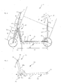
- FIG. 1 shows a first embodiment of a two-wheeled vehicle 2 according to the invention, which solves both the first and the second object of the present invention.
- the two-wheeled vehicle 2 includes a front wheel 4, a rear wheel 6, a handlebar 8 with which the two-wheeled vehicle is steered, a floor space 10, a seat 12, a pedal unit 14 with pedals 16 and a bottom bracket 18. Measured by the bottom bracket 18 the distance L1 to an axis of rotation 20 of the front wheel 4 is greater than the distance L2 of the bottom bracket 18 to a rotational axis 22 of the rear wheel 6.
- a driver can move the two-wheeled vehicle in several ways: he can stand on the standing surface 10 and then from the Repel floor with one leg to move forward or roll upright on standing surface 10. Such a movement is particularly advantageous when it comes quickly to the two-wheeled vehicle, such as a scooter, ascend and descend from it. Further, the driver can sit on the seat 12 and he can move the pedals 16 to drive the rear wheel 6. To increase ride comfort, it may be thought to provide a gearshift, such as a hub gear in the rear wheel 6 or, if the pedal unit 14 is connected to the rear wheel 6 via a drive chain 24, a derailleur with one or two derailleurs may also be used , Preferably, a single drive chain 24 is used.
- a gearshift such as a hub gear in the rear wheel 6 or, if the pedal unit 14 is connected to the rear wheel 6 via a drive chain 24, a derailleur with one or two derailleurs may also be used , Preferably, a single drive chain 24 is used.
- the pedal unit 14 which comprises the pedals 16 and the bottom bracket 18, arranged above the standing surface 10
- the driver can comfortably put his legs from the seat 12 on the pedals 16 and thus assume an ergonomic driving position.
- it can be thought of be provided with a chain guard 26, the pedal unit 14 and the drive chain 24, which on the one hand provides protection against contamination by the drive chain 24, but advantageously also adapted to serve as a footrest for the seated on the seat 12 driver.
- the pedal unit 14 is connected to the rear wheel 6 by a drive train 28 which comprises a drive chain 24, a drive gear 30 connected to the pedals 16, guide gears 32u and 32o, and a driven gear 34.
- the Umlenk leopardson 32u and 32o are part of a deflection 36, which divides the drive train 28 in a first portion, which extends from the rear wheel 6 to the deflection 36, and a second portion which extends from the deflection 36 up to the pedal unit 14.
- the term “up” in a as in FIG. 1 illustrated, ready to drive two-wheeled vehicle 2 'substantially "up” to understand.
- the upper idler gear 32o is associated with an upper leg 38o of the drive chain 24, and the lower idler gear 32u is associated with a lower leg 38u of the drive chain 24.
- the standing surface 10 or a frame element (not shown) running underneath is connected by means of an ascending tube 40 to the headset 42, which serves as a rotary bearing of the handlebar 8 with a handlebar 44 and a fork 46.
- the handlebar 44, and thus the handlebar 8 is preferably height adjustable.
- the pedal unit 14 and in particular the bottom bracket 18 is mounted at the height of the headset 42.
- the bottom bracket 18 is viewed from the seat 12 in front of the headset 42 and arranged in front of the handlebar 44.
- the diverting gears 32o, 32u may be mounted on a frame of the two-wheeled vehicle independently of a chain tensioner.
- the two-wheeled vehicle may include a chain tensioner which does not support one of the idler gears 32 o, 32 u, or the drive chain 24 may be tensioned by proper mounting of the rear wheel 6 alone.
- the deflection 36 has the distance L3 to the axis of rotation 20 of the front wheel and the deflection 36 has the distance L4 to the axis of rotation 22 of the rear wheel.
- L4 is greater than L3, so that the deflection is arranged closer to the front wheel than the rear wheel.
- the first portion of the drive train preferably extends substantially parallel to the standing surface, wherein it is preferred that the first portion of the drive train extends below the standing surface. This is preferably made possible by the fact that the height offset Hv of Umlenk leopard scholar 32u and 32o is smaller than twice the diameter D of the largest Umlenk leopardrades the Umlenk leopardweg 32u, 32o, more preferably smaller than the diameter D, most preferably less than 0.5 D.
- the height offset Hv in FIG. 1 chosen large, as are the Umlenk leopard scholar 32u and 32o in FIG. 1 the same size, but none of this information is to be considered as a restriction). Furthermore, in a preferred embodiment of the Height offset less than 10 cm, more preferably less than 5 cm, most preferably less than 1 cm.
- the arrangement of the Umlenk leopardson 32u, 32o is preferably selected so that the upper strand 38o of the drive chain 24 and the lower strand 38u of the drive chain 24, at least in sections, for example in a portion between the deflector 36 and the drive gear 30 or in a section between the Deflection 36 and the driven gear 34, substantially parallel to each other and preferably spaced apart.
- the first portion of the powertrain 28 is substantially parallel to a plane on which the two-wheeled vehicle is positioned, and thus substantially parallel to a flat connection of the rear wheel and front wheel support points (thus, the first portion of the powertrain preferably runs along a flat road essentially horizontal).
- the two-wheeled vehicle is equipped with a tread brake 50 on the rear wheel.
- a tread brake 50 on the rear wheel.
- a coaster brake as in FIG FIG. 1 shown first embodiment
- a disc brake or a rim brake on the rear wheel 6 is provided on the front wheel 4.
- a rim brake 52 may be provided with a brake lever 54 on the handlebar 8.
- the rim brake 52 may be a disc brake or a tread brake be replaced.
- the seat 12 can be adjusted in height in the direction of the double arrow h up and down in a, preferably provided with a clamping mechanism, seat tube 56 in conjunction with a seat post 58.
- the saddle 12 is preferably adjustable in and in the opposite direction of travel (in, direction of the double arrow I). This can be realized for example by a rail 60 with a clamp 62.
- the seat 12 is arranged substantially above the axis of rotation 22 of the rear wheel, which is also an axis of rotation of the rear wheel 6.
- FIG. 1 the two-wheeled vehicle is shown in its operating state. To be in the transport state (see Fig.
- the saddle 12 is preferably folded on a hinge 64 in the direction of the arrow K1 on the standing surface 10, the transition back to the operating state (the position of the seat 12 in the operating state is indicated by dashed lines) an oppositely directed movement is performed.
- the first hinge 64 is preferably secured in the operating state by a lock, for example a screw connection.
- the handlebar 8 can also be folded down on a second hinge 66.
- the handlebar 8 is folded in the direction of the arrow K2 on the standing surface 10 in the transition from the operating state to the transport state, the transition back to the operating state (the position of the handlebar 8 in the operating state is indicated by dashed lines) an oppositely directed movement is performed.
- the outer dimension Q2 in the direction Q of the two-wheeled vehicle 2 is reduced from the outer dimension Q1 of the two-wheeled vehicle 2 in the operating state.
- the height H2 (in the direction H) of the two-wheeled vehicle 2 in the transport state is less than the height H1 of the two-wheeled vehicle 2 in the operating state.
- the two-wheeled vehicle 2 is adapted to be moved by the driver by pushing off a ground, or to be driven by the driver sitting on the seat 12 by moving the pedals 14.
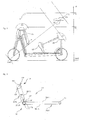
- the second embodiment of the two-wheeled vehicle according to the invention differs only by the configuration of a drive train of the first embodiment. In the following, only the differences from the first embodiment will be described. for the further construction and alternative construction of the second embodiment of the two-wheeled vehicle according to the invention, reference is expressly made to the first embodiment.
- the reference numerals for elements of the second embodiment are each provided with an apostrophe.
- FIGS. 4 . 5a and 5b Referring to the elements shown which are substantially the same as those of the first embodiment, their reference numerals are used from the first embodiment.
- a pedal unit 14 ' is connected to a rear wheel 6 by a drive train 28', which a first drive chain 24'a, a second drive chain 24'b, a pedestal 16 'connected to the drive gear 30', a double gear 68 ' and a driven gear 34 '.
- the first drive chain 24'a is preferably different from the second drive chain 24'b.
- the double gear 68 ' is part of a diverter 36' which extends the driveline 28 'into a first portion which extends from the rear wheel 6 to the diverter 36' and a second portion which extends from the diverter 36 'upwardly to the pedal unit 14' , divided.
- the arrangement of the diverter 26 'with respect to the two-wheeled vehicle in the second embodiment corresponds to the arrangement of the diverter 26 with respect to the two-wheeled vehicle in the first embodiment.
- the double gear 68 ' includes a first gear 70'a and a second gear 70'b.
- the first portion of the powertrain 28 ' includes the first gear 70'a, the driven gear 34' and the first drive chain 24'a connecting the first gear 70'a to the driven gear 34 '.
- the first gear 70'a and the second gear 70'b are offset from each other in the direction of a common axis of rotation and can be connected to each other in a separate embodiment via a connecting element 72 '.
- the double gear 68 ' may either be mounted directly on a frame of the second embodiment of the two-wheeled vehicle according to the invention, or double gear 68' may be mounted on a chain tensioner 48 'attached to this frame.
- the chain tensioner 48 ' includes a slot 74' to allow a particularly simple locking of the chain tensioner, for example with a screw, and also to allow a guide movement of at least a portion of the chain tensioner 48 '. Attachment of the chain tensioner 48 'preferably permits movement of the double gear 68' to simultaneously tension the first 24'a and second drive chains 24'b.
- the attachment of the chain tensioner 48 ' preferably permits movement of the double gear 68' which is neither parallel to a line connecting centers of the double gear 68 'and the driven gear 34' nor parallel to a line connecting centers of the double gear 68 'and the drive gear 30'. runs.
- the double gear 68 ' may extend along the direction of the slot 74' and thus at an angle of about 45 ° with respect to the line connecting the centers of the double gear 68 'and the driven gear 34' and at an angle of about 60 ° with respect to the connecting line the centers of the double gear 68 'and the drive gear 30' move.
- the size (the decisive for the implementation of a rotational movement of a gear in a drive chain movement diameter of the gear, with the same dimensions of the chain links of the first 24'a and second drive chain 24'b this corresponds to the number of a gear existing teeth for engagement with the drive chain) of the drive gear 30 ', the driven gear 34', the first gear 70'a and the second gear 70'b may be selected such that a desired relationship between the rotation of the drive gear 30 'and the driven gear 34 'is adjusted.
- the driven gear 34 'and the first gear 70'a can be made the same size so that the lower strand 38u'a and the upper strand 38o'a of the first drive chain 24'a are substantially parallel to each other, whereby the first portion of the Powertrain 28 'can be arranged to save space under the standing surface 10.
- the drive gear 30 ' may be selected to be larger than the second gear 70'b, wherein the lower strand 38u'b and the upper strand 38o'b of the second drive chain 24'b are substantially not parallel to each other.
- the first gear 70'a and the second gear 70'b may be of different sizes, but it is also possible to make them the same size.
- the Antribsgue by means of drive chains 24'a, 24'b and gears 30 ', 34', 70'a, 70'b be replaced by a drive concept by Antribsriemen and roles.
Landscapes
- Engineering & Computer Science (AREA)
- Mechanical Engineering (AREA)
- Chemical & Material Sciences (AREA)
- Combustion & Propulsion (AREA)
- Transportation (AREA)
- Automatic Cycles, And Cycles In General (AREA)
- Motorcycle And Bicycle Frame (AREA)
Applications Claiming Priority (1)
| Application Number | Priority Date | Filing Date | Title |
|---|---|---|---|
| DE201420000405 DE202014000405U1 (de) | 2014-01-16 | 2014-01-16 | Zweirädriges Fahrzeug |
Publications (2)
| Publication Number | Publication Date |
|---|---|
| EP2896552A2 true EP2896552A2 (fr) | 2015-07-22 |
| EP2896552A3 EP2896552A3 (fr) | 2015-09-30 |
Family
ID=50153846
Family Applications (1)
| Application Number | Title | Priority Date | Filing Date |
|---|---|---|---|
| EP15151427.0A Withdrawn EP2896552A3 (fr) | 2014-01-16 | 2015-01-16 | Véhicule à deux roues |
Country Status (2)
| Country | Link |
|---|---|
| EP (1) | EP2896552A3 (fr) |
| DE (1) | DE202014000405U1 (fr) |
Cited By (1)
| Publication number | Priority date | Publication date | Assignee | Title |
|---|---|---|---|---|
| WO2018013989A1 (fr) | 2016-07-15 | 2018-01-18 | Magna International Inc. | Ensemble essieu de torsion de véhicule |
Families Citing this family (1)
| Publication number | Priority date | Publication date | Assignee | Title |
|---|---|---|---|---|
| US20150210340A1 (en) * | 2014-01-29 | 2015-07-30 | Yao-Chin WANG | Folding vehicle |
Family Cites Families (9)
| Publication number | Priority date | Publication date | Assignee | Title |
|---|---|---|---|---|
| US2183534A (en) * | 1937-04-03 | 1939-12-19 | Adler H Bernier | Vehicle |
| DE828062C (de) * | 1950-10-20 | 1952-01-14 | Paul Kaetsch | Laufroller |
| DE29819701U1 (de) * | 1998-11-04 | 1999-01-21 | Far Great Plastics Industrial Co., Ltd., Kue-Jin Hsiang, Tainan | Doppelfunktions-Tretroller-Fahrrad |
| DE10030502A1 (de) * | 2000-06-21 | 2002-01-03 | Thomas Kretschmer | Fahrrad mit kettenlosem Vorderradantrieb |
| CH696438A5 (de) * | 2001-11-08 | 2007-06-15 | Bonanza Velos Ag | Radfahrzeug als Kombination Fahrrad/Tretroller/Laufrad. |
| US6832774B1 (en) * | 2002-11-13 | 2004-12-21 | Eric R. Zaccagnini | Vehicle convertible between a bicycle and a scooter |
| CN2594127Y (zh) * | 2002-11-29 | 2003-12-24 | 林雪 | 可骑式滑板车 |
| US20060049609A1 (en) * | 2004-09-08 | 2006-03-09 | Sicz Kenneth A | Scooter-bike |
| US20060232040A1 (en) * | 2005-04-13 | 2006-10-19 | Isaac Franco | Scooter Bike |
-
2014
- 2014-01-16 DE DE201420000405 patent/DE202014000405U1/de not_active Expired - Lifetime
-
2015
- 2015-01-16 EP EP15151427.0A patent/EP2896552A3/fr not_active Withdrawn
Non-Patent Citations (1)
| Title |
|---|
| None |
Cited By (1)
| Publication number | Priority date | Publication date | Assignee | Title |
|---|---|---|---|---|
| WO2018013989A1 (fr) | 2016-07-15 | 2018-01-18 | Magna International Inc. | Ensemble essieu de torsion de véhicule |
Also Published As
| Publication number | Publication date |
|---|---|
| DE202014000405U1 (de) | 2014-02-04 |
| EP2896552A3 (fr) | 2015-09-30 |
Similar Documents
| Publication | Publication Date | Title |
|---|---|---|
| EP2768722B1 (fr) | Bicyclette compacte pliable | |
| DE69011098T2 (de) | Stabilisierungsvorrichtung für fahrzeuge. | |
| EP2582570B1 (fr) | Trottinette pour le transport et /ou les charges | |
| DE20206816U1 (de) | Roller | |
| EP0000553A1 (fr) | Véhicule à deux roues du type bicyclette | |
| DE102020120818A1 (de) | Fahrradartiges Fahrzeug | |
| DE102020118623A1 (de) | Dreirädriges Fahrzeug mit mehrteiligem Rahmen | |
| EP2338773A1 (fr) | Trottinette pliable | |
| DE202014000405U1 (de) | Zweirädriges Fahrzeug | |
| EP0586754A1 (fr) | Cadres pour véhicules à voie unique, en particulière bicyclettes | |
| DE10358745B4 (de) | Multifunktionale Kinderbeförderungsvorrichtung | |
| DE4325274C2 (de) | Fahrrad | |
| DE19736266C2 (de) | Liegefahrrad mit Vorderradantrieb | |
| DE102011010909A1 (de) | Bewegliche Beinablagen zum Auf- und Abständern oder zur Sitzabsenkung eines kurvenneigbaren Zwei- oder Dreirades | |
| WO2001002240A1 (fr) | Bicyclette | |
| DE19852153A1 (de) | Tretmobil | |
| DE3727771A1 (de) | Fahrrad | |
| DE19841013A1 (de) | Vorrichtung zur Verhinderung des Herunterfallens für ein rolltreppentaugliches Fahrzeug sowie Fahrzeug mit derartiger Vorrichtung | |
| DE102004033810B4 (de) | Fahrradtandem | |
| AT507556B1 (de) | Tretroller | |
| DE10114121A1 (de) | Vorrichtung für die Sitzflächenanpassung von Fortbewegungsmitteln mit Pedalantrieb | |
| DE9104733U1 (de) | Tandem | |
| WO2015004039A1 (fr) | Trottinette à deux roues pourvue d'un marchepied | |
| DE19515905A1 (de) | Fortbewegungsvorrichtung | |
| DE10159989A1 (de) | Fahrrad |
Legal Events
| Date | Code | Title | Description |
|---|---|---|---|
| PUAI | Public reference made under article 153(3) epc to a published international application that has entered the european phase |
Free format text: ORIGINAL CODE: 0009012 |
|
| 17P | Request for examination filed |
Effective date: 20150116 |
|
| AK | Designated contracting states |
Kind code of ref document: A2 Designated state(s): AL AT BE BG CH CY CZ DE DK EE ES FI FR GB GR HR HU IE IS IT LI LT LU LV MC MK MT NL NO PL PT RO RS SE SI SK SM TR |
|
| AX | Request for extension of the european patent |
Extension state: BA ME |
|
| PUAL | Search report despatched |
Free format text: ORIGINAL CODE: 0009013 |
|
| AK | Designated contracting states |
Kind code of ref document: A3 Designated state(s): AL AT BE BG CH CY CZ DE DK EE ES FI FR GB GR HR HU IE IS IT LI LT LU LV MC MK MT NL NO PL PT RO RS SE SI SK SM TR |
|
| AX | Request for extension of the european patent |
Extension state: BA ME |
|
| RIC1 | Information provided on ipc code assigned before grant |
Ipc: B62K 3/00 20060101AFI20150827BHEP Ipc: B62K 21/16 20060101ALI20150827BHEP Ipc: B62L 1/04 20060101ALI20150827BHEP Ipc: B62K 15/00 20060101ALI20150827BHEP Ipc: B62M 1/36 20130101ALI20150827BHEP |
|
| STAA | Information on the status of an ep patent application or granted ep patent |
Free format text: STATUS: THE APPLICATION IS DEEMED TO BE WITHDRAWN |
|
| 18D | Application deemed to be withdrawn |
Effective date: 20160331 |