EP2896558B1 - Schiffsrudervorrichtung - Google Patents
Schiffsrudervorrichtung Download PDFInfo
- Publication number
- EP2896558B1 EP2896558B1 EP13836895.6A EP13836895A EP2896558B1 EP 2896558 B1 EP2896558 B1 EP 2896558B1 EP 13836895 A EP13836895 A EP 13836895A EP 2896558 B1 EP2896558 B1 EP 2896558B1
- Authority
- EP
- European Patent Office
- Prior art keywords
- steering shaft
- steering
- inversion control
- cylindrical portion
- control pin
- Prior art date
- Legal status (The legal status is an assumption and is not a legal conclusion. Google has not performed a legal analysis and makes no representation as to the accuracy of the status listed.)
- Active
Links
Images


Classifications
-
- G—PHYSICS
- G05—CONTROLLING; REGULATING
- G05G—CONTROL DEVICES OR SYSTEMS INSOFAR AS CHARACTERISED BY MECHANICAL FEATURES ONLY
- G05G5/00—Means for preventing, limiting or returning the movements of parts of a control mechanism, e.g. locking controlling member
- G05G5/04—Stops for limiting movement of members, e.g. adjustable stop
-
- B—PERFORMING OPERATIONS; TRANSPORTING
- B63—SHIPS OR OTHER WATERBORNE VESSELS; RELATED EQUIPMENT
- B63H—MARINE PROPULSION OR STEERING
- B63H20/00—Outboard propulsion units, e.g. outboard motors or Z-drives; Arrangements thereof on vessels
- B63H20/08—Means enabling movement of the position of the propulsion element, e.g. for trim, tilt or steering; Control of trim or tilt
- B63H20/12—Means enabling steering
-
- B—PERFORMING OPERATIONS; TRANSPORTING
- B63—SHIPS OR OTHER WATERBORNE VESSELS; RELATED EQUIPMENT
- B63H—MARINE PROPULSION OR STEERING
- B63H25/00—Steering; Slowing-down otherwise than by use of propulsive elements; Dynamic anchoring, i.e. positioning vessels by means of main or auxiliary propulsive elements
- B63H25/02—Initiating means for steering, for slowing down, otherwise than by use of propulsive elements, or for dynamic anchoring
-
- B—PERFORMING OPERATIONS; TRANSPORTING
- B63—SHIPS OR OTHER WATERBORNE VESSELS; RELATED EQUIPMENT
- B63H—MARINE PROPULSION OR STEERING
- B63H25/00—Steering; Slowing-down otherwise than by use of propulsive elements; Dynamic anchoring, i.e. positioning vessels by means of main or auxiliary propulsive elements
- B63H25/06—Steering by rudders
- B63H25/08—Steering gear
- B63H25/14—Steering gear power assisted; power driven, i.e. using steering engine
- B63H25/18—Transmitting of movement of initiating means to steering engine
- B63H25/24—Transmitting of movement of initiating means to steering engine by electrical means
-
- B—PERFORMING OPERATIONS; TRANSPORTING
- B63—SHIPS OR OTHER WATERBORNE VESSELS; RELATED EQUIPMENT
- B63H—MARINE PROPULSION OR STEERING
- B63H25/00—Steering; Slowing-down otherwise than by use of propulsive elements; Dynamic anchoring, i.e. positioning vessels by means of main or auxiliary propulsive elements
- B63H25/52—Parts for steering not otherwise provided for
-
- G—PHYSICS
- G05—CONTROLLING; REGULATING
- G05G—CONTROL DEVICES OR SYSTEMS INSOFAR AS CHARACTERISED BY MECHANICAL FEATURES ONLY
- G05G5/00—Means for preventing, limiting or returning the movements of parts of a control mechanism, e.g. locking controlling member
- G05G5/03—Means for enhancing the operator's awareness of arrival of the controlling member at a command or datum position; Providing feel, e.g. means for creating a counterforce
-
- B—PERFORMING OPERATIONS; TRANSPORTING
- B63—SHIPS OR OTHER WATERBORNE VESSELS; RELATED EQUIPMENT
- B63H—MARINE PROPULSION OR STEERING
- B63H25/00—Steering; Slowing-down otherwise than by use of propulsive elements; Dynamic anchoring, i.e. positioning vessels by means of main or auxiliary propulsive elements
- B63H25/02—Initiating means for steering, for slowing down, otherwise than by use of propulsive elements, or for dynamic anchoring
- B63H2025/022—Steering wheels; Posts for steering wheels
Definitions
- the present invention relates to an electric helm device for use in steering a boat, and particularly, to a helm device comprising a stop mechanism which can apply resistance to the turning of a steering wheel.
- a steering apparatus of an outboard motor there has been known a steering apparatus comprising a hydraulic pump and a hydraulic actuator.
- a hydraulic pump is provided in a steering wheel (helm).
- a hydraulic actuator is disposed in an outboard motor and is driven by the hydraulic pump.
- the direction of the outboard motor is changed by hydraulic pressure produced by the hydraulic pump.
- a mechanical steering apparatus is known. In the mechanical steering apparatus, rotary motion of a steering wheel is transmitted to an outboard motor via a push-pull cable. Either type of steering apparatus is operated manually (i.e., by the boat operator's power). Accordingly, conventional steering apparatuses leave room for improvement in that a relatively large control force is required depending on the boat handling conditions.
- An electric steering apparatus comprises a helm device comprising a sensor for detecting an operating angle of a steering wheel, and an actuator unit which is driven by electrical signals output from the helm device.
- a helm device comprising a sensor for detecting an operating angle of a steering wheel
- an actuator unit which is driven by electrical signals output from the helm device.
- the friction mechanism comprises a plurality of fixed disks, a plurality of rotatable disks, and an electromagnet.
- the fixed disks and the rotatable disks are overlapped on one another alternately.
- the disks are composed such that they are pressed against one another by the electromagnet. Tooth portions formed on an outer peripheral portion of each of the fixed disks engage with a fixed spline member. Tooth portions formed on an inner peripheral portion of each of the rotatable disks engage with a rotatable spline member which rotates together with a steering shaft.
- the steering wheel is locked by maximizing electric power to be supplied to the electromagnet to prevent the steering wheel from being turned further when it is operated to the maximum to the starboard or the port side.
- the aforementioned locked state must be cancelled. Accordingly, play is provided in an engagement portion between each tooth portion of the disk and the spline member.
- the present invention provides a helm device of a boat which can securely cancel the locked state in reversal of a steering shaft.
- the helm device of the present invention comprises a case secured to a hull (boat body), a steering shaft which is rotatably arranged in the case and on which a steering wheel is mounted, a sensor configured to detect rotation of the steering shaft, and a stop mechanism configured to stop rotation of the steering shaft when the steering wheel is turned to a maximum steering angle.
- the stop mechanism comprises a rotation member being attached to the steering shaft and comprising a cylindrical portion, the cylindrical portion being relatively rotatable with respect to the steering shaft in a circumferential direction.
- the stop mechanism comprises also a fixed disk accommodated in the case, a rotatable disk arranged to be opposed to the fixed disk and configured to rotate together with the rotation member, and an electromagnet which produces the frictional force by pressing the fixed disk and the rotatable disk against each other.
- the stop mechanism comprises further an elastic member which urges the steering shaft in a direction of the projecting outward from the case and an inversion control pin mechanism.
- the inversion control pin mechanism includes an inversion control pin and first and second pin receiving stopper walls provided at both ends of a slit.
- the inversion control pin is provided in a radial direction of the steering shaft, extending through both the cylindrical portion and the steering shaft, and is secured to one of the steering shaft and the cylindrical portion.
- the slit is formed in the other one of the steering shaft and the cylindrical portion, and through which the inversion control pin is inserted to be movable in the circumferential direction.
- the first pin receiving stopper wall is formed on one end of the slit in the circumferential direction, and when the steering shaft rotates in a first direction, the first pin receiving stopper wall contacts the inversion control pin, thereby rotating the cylindrical portion in the first direction, and when the steering shaft rotates in a second direction, the first pin receiving stopper wall is separated from the inversion control pin by an angle which is greater than or equal to a minimum detection angle detectable by the sensor.
- the second pin receiving stopper wall is formed on the other end of the slit in the circumferential direction, and when the steering shaft rotates in the second direction, the second pin receiving stopper wall contacts the inversion control pin, thereby rotating the cylindrical portion in the second direction, and when the steering shaft rotates in the first direction, the second pin receiving stopper wall is separated from the inversion control pin by an angle which is greater than or equal to the minimum detection angle detectable by the sensor.
- the inversion control pin is secured to the steering shaft, and the first and the second pin receiving stopper walls are formed on the cylindrical portion.
- the inversion control pin formed of a screw member is secured to the steering shaft, and the first and the second pin receiving stopper walls are formed on the cylindrical portion.
- the inversion control pin may be secured to the cylindrical portion, and the first and the second pin receiving stopper walls may be formed on the steering shaft.
- the inversion control pin formed of a screw member may be secured to the cylindrical portion, and the first and the second pin receiving stopper walls may be formed on the steering shaft.
- the inversion control pin moves from one of the pin receiving stopper walls to the other pin receiving stopper wall within the range of inversion allowance angle. Accordingly, reversal of the steering shaft can be detected by a sensor. The lock of the steering shaft by the stop mechanism can be cancelled.
- the inversion allowance angle can be adjusted by changing the diameter of the inversion control pin, or changing the distance between the first and second pin receiving stopper walls.
- a boat comprising a helm device according to a first embodiment will now be described with reference to FIGS. 1 to 10 .
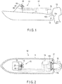
- FIGS. 1 and 2 illustrate an example of a boat 10.
- the boat 10 comprises a hull 11, an outboard motor 12, and a steering apparatus 13.
- the steering apparatus 13 comprises a helm device 16 comprising a steering wheel 15, an electric actuator unit 17 configured to change a steering angle of the outboard motor 12, and a control unit 18.
- the control unit 18 is electrically connected to the helm device 16 and the actuator unit 17.
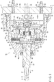
- FIG. 3 is a cross-sectional view showing an example of the helm device 16.
- the helm device 16 comprises a waterproof case 21, a steering shaft 22 inserted in the case 21, a stop mechanism 23 provided within the case 21, an assist spring 24, a sensor (helm sensor) 25 for detecting rotation of the steering shaft 22, etc.
- the case 21 comprises a first case member 21a and a second case member 21b.
- the second case member 21b is secured to the first case member 21a by a fixing member 30.
- a cover member 31 is inserted into the second case member 21b.
- the cover member 31 is secured to the second case member 21b by fixing members 32.
- the steering shaft 22 is rotatably supported by bearing members 38 and 39, and can be rotated in first direction A and second direction B about axis X 0 ( FIG. 3 ).
- a seal member 40 is provided between the steering shaft 22 and an inner peripheral surface of the hole 35.
- One of end portions of the steering shaft 22 is projected outward from the case 21. On this end portion of the steering shaft 22, a fitting portion 41 is formed. The steering wheel 15 is secured to the fitting portion 41. The other end portion of the steering shaft 22 is positioned inside the case 21. A magnet 45 for use as a member to be detected that constitutes a part of the sensor 25 is disposed on the other end portion.
- a circuit board 52 is accommodated in a recess 50 formed in the cover member 31.
- the circuit board 52 is secured to the cover member 31 by a fixing member 53.
- An element 55 for detecting the magnet 45 is disposed on the circuit board 52.
- the magnet 45 and the element 55 constitute the sensor (helm sensor) 25 for detecting the degree of rotation and the direction of rotation of the steering shaft 22.
- An electrical signal concerning the manipulated variable (operating angle) of the steering shaft 22 detected by the sensor 25 is output to the control unit 18 via a conducting member 56.
- the case 21 is secured to a helm mounting wall 60, which is a part of the hull 11, by means of a mounting bolt 61 and a nut 62.
- the mounting bolt 61 is provided in the case 21.
- the mounting bolt 61 projects from an end surface 63 of the case 21 into area S of the hull.
- the mounting bolt 61 is inserted into a through-hole 64 formed in the helm mounting wall 60.
- a through-hole 65 for passing through the conducting member 56 is formed.
- the steering shaft 22 is urged in the direction of projecting outward from the case 21 (i.e., the direction indicated by arrow H in FIG. 3 ) by the elastic member 70.
- the elastic member 70 also has the function of absorbing vibration, etc., in the direction of axis X 0 of the steering shaft 22 since the elastic member 70 deforms when it is subjected to a load input in the direction of axis X 0 .
- a holder member 71 is provided at the end portion of the steering shaft 22 positioned inside the case 21, a holder member 71 is provided.
- the holder member 71 is inserted into a recess 72 formed in a central part of the cover member 31.
- the holder member 71 is supported to be rotatable about axis X 0 of the steering shaft 22 by a support base 73.
- the magnet 45 On an end surface of the holder member 71, the magnet 45, which is an example of a member to be detected, is provided.
- the magnet 45 is located on an extended line of axis X 0 of the steering shaft 22.
- the sensor 25 On the circuit board 52, the sensor 25 comprising the element 55 is disposed.
- the element 55 of the sensor 25 detects a rotational position of the steering shaft 22 by magnetic force produced by the magnet 45.
- the holder member 71 is provided with a pin 75.
- the pin 75 extends in a radial direction of the holder member 71.
- the steering shaft 22 and the holder member 71 are connected to each other by the pin 75.
- the holder member 71 can be rotated with the steering shaft 22.
- the holder member 71 is movable relative to the steering shaft 22 in the direction of axis X 0 .
- a spring 76 formed of, for example, a compression coil spring is accommodated in the end portion of the steering shaft 22 in the end portion of the steering shaft 22 .
- the holder member 71 is constantly urged toward the sensor 25 from the steering shaft 22 by the spring 76. Accordingly, the holder 71 is maintained such that its position relative to the sensor 25 in the direction of axis X 0 is constant regardless of the position of the steering shaft 22 in the direction of axis X 0 . For this reason, even if the position of the steering shaft 22 is shifted in the direction of axis X 0 , a distance from the member to be detected (the magnet 31) to the sensor 25 can be kept constant. Accordingly, the sensor 25 can constantly output stable signals.
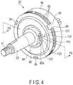
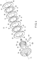
- FIG. 4 is a perspective view of the stop mechanism 23, and FIG. 5 is an exploded perspective view showing a part of the stop mechanism 23.
- FIG. 6 is a cross-sectional view taken along line F6-F6 of FIG. 4
- FIG. 7 is a partial side view of the stop mechanism 23.
- the stop mechanism 23 comprises a rotation member 80 attached to the steering shaft 22, a plurality of rotatable disks 81 which rotate together with the rotation member 80, a plurality of fixed disks 82 arranged to be opposed to the rotatable disks 81, an electromagnet 83, and an armature 84.
- the rotatable disks 81 and the fixed disks 82 are alternately arranged in a through-thickness direction.
- the stop mechanism 23 is in contact with the oil filled in the chamber 36.
- the rotation member 80 is allowed to perform relative rotation with respect to the steering shaft 22 within the range of inversion allowance angle ⁇ by an inversion control pin mechanism 125 which will be described later in detail.
- the rotation member 80 comprises a cylindrical portion 80a, and a disk mounting portion 80b having a larger diameter than the cylindrical portion 80a.
- a disk mounting portion 80b On an outer peripheral surface of the disk mounting portion 80b, splines 85 along axis X 0 are formed.
- tooth portions 86 On an inner peripheral portion of each rotatable disk 81, tooth portions 86 which engage with the splines 85 are formed. Consequently, the rotatable disks 81 are held to be movable on the rotation member 80 in the direction of axis X 0 , and can also rotate integrally with the rotation member 80.
- the electromagnet 83 comprises a yoke 90 and a coil 91. Electric power from a power source not shown is supplied to the coil 91 through the control unit 18. A seal member 92 is provided between an outer peripheral surface of the yoke 90 and an inner peripheral surface of the case 21.
- the armature 84 is movable in a direction along axis X 0 of the steering shaft 22. The armature 84 is attracted to the yoke 90 by magnetic force produced when electric power is supplied to the coil 91. That is, the armature 84 can be moved in the direction of pressing the rotatable disks 81 and the fixed disks 82 against one another.
- the yoke 90 is secured to the case 21 by fixing members 93. On the outer peripheral portion of the yoke 90, a protrusion 95 is formed. A recess 96 formed on an outer peripheral portion of each of the fixed disks 82 engages with the protrusion 95. That is, the fixed disks 82 held by the yoke 90 such that they are movable relative to the case 21 in the direction of axis X 0 of the steering shaft 22, and they do not rotate relative to the case 21.
- the assist spring 24 is positioned between the spring receiving surface 37 of the case 21 and the armature 84 in such a state that the spring 24 is deformed by application of an initial load.
- the armature 84 is constantly urged toward the yoke 90.
- the electromagnet 83 attracts the armature 84 only when electric power is supplied to the coil 91. In other words, when the electromagnet 83 is not energized, the rotatable disks 81 and the fixed disks 82 are sandwiched between the armature 84 and the yoke 90 by the repulsive load of the assist spring 24 and produce frictional force (friction).
- the electromagnet 83 produces magnetic force according to the magnitude of electric power supplied to the coil 91, thereby attracting the armature 84. Accordingly, when the electromagnet 83 is energized, the rotatable disks 81 and the fixed disks 82 are sandwiched between the armature 84 and the yoke 90 by force obtained by adding the repulsive load of the assist spring 24 and attractive force of the electromagnet 83. That is, according to the magnitude of electric power supplied to the electromagnet 83, frictional force of the stop mechanism 23 can be varied. Consequently, steering effort on the steering wheel 15 (resistance) can be varied.
- a computer program capable of changing electric power to be supplied to the coil 91 depending on the boat operator's desire or boat handling conditions is installed. For example, by operating an adjustment operation portion 98 arranged near a helm position (steering seat) of the boat 10, electric power to be supplied to the electromagnet 83 can be varied.
- the adjustment operation portion 98 When the resistance (steering effort) in operating the steering wheel 15 is to be increased, the adjustment operation portion 98 is operated in the direction of "high friction". In that case, the electric power supplied to the electromagnet 83 is increased, thereby increasing the magnetic field of the electromagnet 83. Accordingly, as the armature 84 is attracted with greater force, friction of the stop mechanism 23 is increased. Thus, the steering effort can be increased.
- the adjustment operation portion 98 is operated in the direction of "low friction". In that case, the electric power supplied to the electromagnet 83 is reduced and the magnetic field of the electromagnet 83 is reduced, so that steering effort is reduced as the friction of the stop mechanism 23 is reduced.
- control unit 18 has the function of locking the steering shaft 22 so that the steering wheel 15 does not turn further than the maximum steering angle when it is turned to the maximum steering angle from the neutral position. That is, when the steering wheel 15 is turned to the maximum to the starboard or the port side up to the number of steering wheel turns, the control unit 18 controls the electric power supplied to the electromagnet 83 to be maximum, and the magnetic field of the electromagnet 83 to be maximum. Accordingly, the rotatable disks 81 and the fixed disks 82 are locked to one other. The steering wheel 15 is thereby brought into a locked state, and prevented from being turned further.
- control unit 18 is equipped with a computer program as the means for supplying the electromagnet 83 with electric power which locks the disks 81 and 82 with one another when the number of turns of the steering wheel 15 (the amount of turn from the neutral position) reaches the preset number of steering wheel turns.
- a radial through-hole 100 is formed in the steering shaft 22. Further, an inversion control pin 110 is inserted into the through-hole 100.
- the inversion control pin 110 may be secured to the steering shaft 22 by, for example, being inserted into the through-hole 100 by press-fit. Both ends of the inversion control pin 110 protrude in a radial direction of the steering shaft 22 from an outer peripheral surface of the steering shaft 22.
- the rotation member 80 comprises the cylindrical portion 80a and the disk mounting portion 80b.
- the rotation member 80 can be relatively rotated with respect to the steering shaft 22 in a circumferential direction about axis X 0 .
- a pair of slits 120 is formed in symmetrical positions under a 180-degree rotation in a circumferential direction of the cylindrical portion 80a.
- These slits 120 are shaped to be elongated in the circumferential direction of the cylindrical portion 80a, and have elongated circular shapes as seen from a side surface of the cylindrical portion 80a.
- a first pin receiving stopper wall 121 is formed at one end of each of the slits 120 in the circumferential direction.
- a second pin receiving stopper wall 122 is formed at the other end of each of the slits 120 in the circumferential direction.
- the pin receiving stopper walls 121 and 122 are formed into semicircular shapes, respectively, corresponding to the shape (circular shape) of the outer peripheral surface of the inversion control pin 110 having a cylindrical form.
- Distance L1 ( FIG. 7 ) between inner surfaces 123 and 124 of each of the slits 120 is set to be slightly larger than the outer diameter of the inversion control pin 110. In this way, the inversion control pin 110 is prevented from moving in the direction of axis X 0 , while being allowed to move in the circumferential direction.
- the inversion control pin 110 extends in the radial direction of the steering shaft 22 and the cylindrical portion 80a.
- the inversion control pin 110 extends through the steering shaft 22 and the cylindrical portion 80a.
- both ends of the inversion control pin 110 are inserted to be movable in the circumferential direction.
- the inversion control pin 110 can be moved within the range of inversion allowance angle ⁇ between the first and the second pin receiving stopper walls 121 and 122.
- the rotation member 80 can be relatively rotated with respect to the steering shaft 22 within the range of inversion allowance angle ⁇ .
- Inversion allowance angle ⁇ is greater than the minimum detection angle detectable by the sensor 25.
- the inversion control pin 110, the slits 120 having the inner surfaces 123 and 124, the first and second pin receiving stopper walls 121 and 122, etc., constitute the inversion control pin mechanism 125.
- FIG. 8 shows a part of the outboard motor 12 and the actuator unit 17.
- the outboard motor 12 is supported on a rear wall 11a of the hull 11 by a bracket 130.
- FIG. 9 is a plan view of the actuator unit 17 and the bracket 130 as seen from above.
- the bracket 130 comprises fixed bracket portions 131a and 131b secured to the hull 11, and a movable bracket portion 133.
- the movable bracket portion 133 is movable upward and downward about a rotation axis 132 relative to the fixed bracket portions 131a and 131b.
- An example of the rotation axis 132 is a tilt axis which serves as the center when tilting up the outboard motor 12, and the rotation axis 132 extends transversely, that is, horizontally, relative to the hull 11.
- the outboard motor 12 is mounted on the movable bracket portion 133.
- the movable bracket portion 133 can be moved upward and downward between a tilt-down position and a tilt-up position by a tilt drive force such as a hydraulic actuator not shown. That is, the outboard motor 12 has a tilt-up function.
- the movable bracket portion 133 is provided with a steering arm 135 for changing a steering direction of the outboard motor 12.
- the steering arm 135 can be pivoted laterally (left and right) about a pivot 136 ( FIG. 9 ) provided on the movable bracket portion 133. By moving the steering arm 135 laterally, the outboard motor 12 can be moved in the starboard direction or the port direction with respect to the hull 11.
- FIG. 9 shows the state in which the steering arm 135 is in the neutral position.
- the steering arm 135 can be moved in the starboard direction or the port direction.
- the actuator unit 17 comprises a first support arm 140 and a second support arm 141.
- the first support arm 140 is secured to one end of the rotation axis (tilt axis) 132 by a fastener 142 such as a nut.
- the second support arm 141 is secured to the other end of the rotation axis 132 by a fastener 144 such as a nut.
- the actuator unit 17 comprises an electric actuator 150.
- the electric actuator 150 is secured to both ends of the rotation axis 132 via the first and the second support arms 140 and 141.
- FIG. 10 is a cross-sectional view taken along an axial direction of the electric actuator 150.
- the electric actuator 150 comprises a cylindrical cover member 151, a first electric motor 152, a second electric motor 153, a feed screw 154, a nut member 155, etc.
- the cover member 151 extends transversely relative to the hull 11.
- the first electric motor 152 is mounted on one end of the cover member 151.
- the second electric motor 153 is mounted on the other end of the cover member 151.
- the feed screw 154 rotates by the electric motors 152 and 153.
- a slit 151a is formed in the cover member 151 along axis X1.
- the first electric motor 152 comprises a motor body 156 and a rotor 157 configured to rotate by electric power.
- the motor body 156 is secured to the first support arm 140 by a fastener 158 such as a nut.
- the second electric motor 153 comprises a motor body 160 and a rotor 161 configured to rotate by electric power.
- the motor body 160 is secured to the second support arm 141 by a fastener 163 such as a nut.
- a plurality of (for example, four) connecting rods 165 are arranged parallel to one another between the motor body 156 of the first electric motor 152 and the motor body 160 of the second electric motor 153. These connecting rods 165 are disposed outside the cover member 151, and extend along axis X1 ( FIG. 10 ) of the cover member 151. The motor body 156 of the first electric motor 152 and the motor body 160 of the second electric motor 153 are connected to each other by these connecting rods 165.
- the feed screw 154 is arranged inside the cover member 151.
- the feed screw 154 is disposed along axis X1 of the cover member 151.
- the feed screw 154 can be rotated in first direction R1 and second direction R2 ( FIG. 10 ) by the torques produced by the first electric motor 152 and the second electric motor 153.
- the nut member 155 is accommodated within the cover member 151.
- the nut member 155 is threadably mounted on the feed screw 154 to be rotatatable. When the feed screw 154 is relatively rotated with respect to the nut member 155, the nut member 155 reciprocate in first direction F1 or second direction F2 ( FIG. 10 ) along axis X1 within the cover member 151.
- the nut member 155 is provided with a drive arm 171.
- the drive arm 171 moves integrally with the nut member 155 in first direction F1 or second direction F2 along the slit 151a.
- a long hole 172 is formed in the drive arm 171.
- An engagement member 173 is inserted into the long hole 172.
- the engagement member 173 is movable longitudinally relative to the drive arm 171 along the long hole 172, but its lateral movement is restricted.
- the engagement member 173 is connected to the receiving portion 139 of the steering arm 135.
- the drive arm 171 is moved in first direction F1 or second direction F2
- the engagement member 173 is moved in the same direction as the drive arm 171.
- the steering arm 135 is moved in the starboard direction or the port direction.
- the feed screw 154 is covered by protective boots 180 and 181 which can expand and contract in the direction of axis X1.
- the actuator unit 17 comprises a neutral position detection sensor 190, and a steering angle sensor 191.
- the neutral position detection sensor 190 has the function of detecting whether the steering arm 135 is in the neutral position.
- the steering sensor 191 has the function of detecting the steering angle of the steering arm 135. When the steering arm 135 is in the neutral position, a signal indicative of the neutral position is output from the neutral position detection sensor 190 to the control unit 18.
- the degree of rotation (steering angle) of the steering wheel 15 is detected by the sensor 25, and electrical signals regarding the direction of steering and the magnitude of the steering angle are transmitted to the control unit 18.
- the control unit 18 rotates the first and the second electric motors 152 and 153 such that a target steering angle output from the sensor 25 to the control unit 18 agrees with the actual steering angle of the outboard motor 12 detected by the steering angle sensor 191.
- the control unit 18 assumes the neutral position of the steering arm 135 detected by the neutral position detection sensor 190 as a reference position in the steering angle. Further, the control unit 18 controls the electric motors 152 and 153 such that the actual steering angle of the steering arm 135 detected by the steering angle sensor 191 agrees with the output (target steering angle) of the steering wheel 15.
- the motors 152 and 153 rotate in first direction R1 ( FIG. 10 ). Accordingly, the drive arm 171 is moved in first direction F1, and the steering arm 135 is moved toward a starboard position shown as Q1 in FIG. 9 .
- the motors 152 and 153 stop and the drive arm 171 also stops.
- the motors 152 and 153 rotate in second direction R2. Accordingly, the drive arm 171 is moved in second direction F2 ( FIG. 10 ), and the steering arm 135 is moved toward a port position shown as Q2 in FIG. 9 .
- the motors 152 and 153 stop and the drive arm 171 also stops.
- the electromagnet 83 of the stop mechanism 23 which is provided in the helm device 16 is controlled by the control unit 18. Further, as the boat operator operates the adjustment operation portion 98, control force on the steering wheel 15 (resistance) can be adjusted. Also, by automatically controlling the electromagnet 83 based on signals from various sensors input to the control unit 18, the helm device 16 can be adjusted to provide a suitable state for boat handling conditions.
- the inversion control pin 110 In steering, when the steering shaft 22 is rotated in first direction A ( FIGS. 3 and 6 ) by the steering wheel 15, the inversion control pin 110 contacts the first pin receiving stopper wall 121. Accordingly, the rotation member 80 rotates integrally with the steering shaft 22 in first direction A. At this time, the inversion control pin 110 is separated from the second pin receiving stopper wall 122 by an angle which is greater than or equal to the minimum detection angle detectable by the sensor 25.
- the control unit 18 maximizes the electric power to be supplied to the electromagnet 83. Thus, the disks 81 and 82 are locked to one other.
- the inversion control pin 110 contacts the second pin receiving stopper wall 122. Accordingly, the rotation member 80 rotates integrally with the steering shaft 22 in second direction B. At this time, the inversion control pin 110 is separated from the first pin receiving stopper wall 121 by an angle which is greater than or equal to the minimum detection angle detectable by the sensor 25.
- the control unit 18 maximizes the electric power to be supplied to the electromagnet 83. Thus, the disks 81 and 82 are locked to one other.
- the steering shaft 22 can be relatively rotated with respect to the rotation member 80 within the range of inversion allowance angle ⁇ . Accordingly, even in a state where the disks 81 and 82 are locked to one another by the electromagnet 83 at the maximum steering angle position, the steering shaft 22 can rotate in the opposite direction within the range of inversion allowance angle ⁇ exceeding the minimum detection angle (the detection resolution) of the sensor 25. Thus, the sensor 25 can output a signal for cancelling the locking.
- the inversion allowance angle ⁇ can be easily adjusted by changing the diameter (thickness) of the inversion control pin 110, or changing the distance between the pin receiving stopper walls 121 and 122.
- FIG. 11 illustrates a stop mechanism 23A according to a second embodiment.
- An inversion control pin mechanism 125 of the stop mechanism 23A comprises a pair of inversion control pins 110' each formed of a screw member. These inversion control pins 110' are screwed into both sides of a steering shaft 22 to be secured.
- a pair of slits 120 is formed in a cylindrical portion 80a of a rotation member 80.
- a first pin receiving stopper wall 121 and a second pin receiving stopper wall 122 are formed in each of the slits 120.
- the inversion control pins 110' are inserted into the slits 120, respectively.
- the steering shaft 22 can be relatively rotated with respect to the rotation member 80 within the range of inversion allowance angle ⁇ .
- FIG. 12 illustrates a stop mechanism 23B according to a third embodiment.
- this stop mechanism 23B for parts which are in common with the parts of the stop mechanism 23 ( FIGS. 3 to 7 ) of the first embodiment, the same reference numbers as those of the stop mechanism 23 of the first embodiment are added, and explanations of them are omitted.
- An inversion control pin 110 of the stop mechanism 23B is secured to a cylindrical portion 80a of a rotation member 80.
- a slit 120 into which the inversion control pin 110 is inserted is formed in a steering shaft 22. At both ends of the slit 120, first and second pin receiving stopper walls 121 and 122 are formed.
- the steering shaft 22 can be relatively rotated with respect to the rotation member 80 within the range of inversion allowance angle ⁇ .
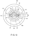
- FIG. 13 illustrates a stop mechanism 23C according to a fourth embodiment.
- An inversion control pin mechanism 125 of the stop mechanism 23C comprises a pair of inversion control pins 110' each formed of a screw member. These inversion control pins 110' are secured by being screwed into both sides of a cylindrical portion 80a of a rotation member 80. A pair of slits 120 is formed in a steering shaft 22.
- a first pin receiving stopper wall 121 and a second pin receiving stopper wall 122 are formed in each of the slits 120.
- the inversion control pins 110' are inserted into the slits 120, respectively.
- the steering shaft 22 can be relatively rotated with respect to the rotation member 80 within the range of inversion allowance angle ⁇ .
- each member which constitutes the helm device such as the case or the steering shaft of the helm device, and the disks, electromagnet, inversion control pin, slit, and first and second pin receiving stopper walls of the stop mechanism, may be modified variously.
- the present invention can be applied to not only a helm device for use in steering a boat, but also an electric helm device for various apparatuses comprising a steering apparatus.
Landscapes
- Engineering & Computer Science (AREA)
- Chemical & Material Sciences (AREA)
- Combustion & Propulsion (AREA)
- Mechanical Engineering (AREA)
- Ocean & Marine Engineering (AREA)
- Physics & Mathematics (AREA)
- General Physics & Mathematics (AREA)
- Automation & Control Theory (AREA)
- Power Steering Mechanism (AREA)
Claims (5)
- Steuerrudervorrichtung eines Boots, dadurch gekennzeichnet, dass sie umfasst:ein Gehäuse (21), das an einem Bootsrumpf befestigt ist;eine Lenkwelle (22), die drehbeweglich im Gehäuse (21) angeordnet ist, und an der ein Lenkrad (15) angebracht ist;einen Sensor (25), der dazu ausgelegt ist, eine Drehung der Lenkwelle (22) zu erfassen; undeinen Stoppmechanismus (23, 23A, 23B, 23C), der dazu ausgelegt ist, eine Drehung der Lenkwelle (22) zu stoppen, wenn das Lenkrad (15) auf einen maximalen Lenkwinkel gedreht ist,wobei der Stoppmechanismus (23, 23A, 23B, 23C) umfasst:ein Drehteil (80), das an der Lenkwelle (22) befestigt ist und einen zylindrischen Abschnitt (80a) umfasst, wobei der zylindrische Abschnitt (80a) in einer Umfangsrichtung in Bezug auf die Lenkwelle (22) relativ drehbeweglich ist;eine feststehende Scheibe (82), die im Gehäuse (21) aufgenommen ist;eine drehbewegliche Scheibe (81), die der feststehenden Scheibe (82) gegenüberliegend angeordnet und dazu ausgelegt ist, sich zusammen mit dem Drehteil (80) zu drehen; undeinen Elektromagneten (83), der die Reibungskraft durch Aneinanderdrücken der feststehenden Scheibe (82) und der drehbeweglichen Scheibe (81) erzeugt,dadurch gekennzeichnet, dass die Steuerrudervorrichtung darüber hinaus umfasst:ein elastisches Teil (70), das die Lenkwelle (22) in eine aus dem Gehäuse (21) nach außen vorstehende Richtung drückt,einen Umkehrungssteuerstift (110, 110'), der in einer radialen Richtung der Lenkwelle (22) sich sowohl durch den zylindrischen Abschnitt (80a) als auch die Lenkwelle (22) erstreckend vorgesehen ist, wobei der Umkehrungssteuerstift (110, 110') an der Lenkwelle (22) oder dem zylindrischen Abschnitt (80a) befestigt ist;einen Schlitz (120), der im jeweils anderen Element, der Lenkwelle (22) oder dem zylindrischen Abschnitt (80a) ausgebildet ist, und durch den der Umkehrungssteuerstift (110, 110') in der Umfangsrichtung beweglich eingesetzt ist, wobei der Schlitz (120) ein Paar Innenflächen (123, 124) umfasst, die verhindern, dass sich der Umkehrungssteuerstift (110, 110') in einer Richtung einer Achse (X0) der Lenkwelle (22) bewegt;eine erste Stiftaufnahmeanschlagwand (121), die an einem Ende des Schlitzes (120) in der Umfangsrichtung ausgebildet ist, wobei, wenn sich die Lenkwelle (22) in einer ersten Richtung (A) dreht, die erste Stiftaufnahmeanschlagwand (121) den Umkehrungssteuerstift (110, 110') berührt, wodurch der zylindrische Abschnitt (80a) in der ersten Richtung (A) gedreht wird, und wenn sich die Lenkwelle (22) in einer zweiten Richtung (B) dreht, die erste Stiftaufnahmeanschlagwand (121) vom Umkehrungssteuerstift (110, 110') um einen Winkel getrennt ist, der größer als ein oder gleich einem durch den Sensor (25) erfassbaren Mindesterfassungswinkel ist; undeine zweite Stiftaufnahmeanschlagwand (122), die am anderen Ende des Schlitzes (120) in der Umfangsrichtung ausgebildet ist, wobei, wenn sich die Lenkwelle (22) in der zweiten Richtung (B) dreht, die zweite Stiftaufnahmeanschlagwand (122) den Umkehrungssteuerstift (110, 110') berührt, wodurch der zylindrische Abschnitt (80a) in der zweiten Richtung (B) gedreht wird, und wenn sich die Lenkwelle (22) in der ersten Richtung (A) dreht, die zweite Stiftaufnahmeanschlagwand (122) vom Umkehrungssteuerstift (110, 110') um einen Winkel getrennt ist, der größer als ein oder gleich einem durch den Sensor (25) erfassbaren Mindesterfassungswinkel ist.
- Steuerrudervorrichtung nach Anspruch 1, dadurch gekennzeichnet, dass der Umkehrungssteuerstift (110') an der Lenkwelle (22) befestigt ist und die erste und zweite Stiftaufnahmeanschlagwand (121, 122) auf dem zylindrischen Abschnitt (80a) ausgebildet sind.
- Steuerrudervorrichtung nach Anspruch 1, dadurch gekennzeichnet, dass der aus einem Schraubenteil gebildete Umkehrungssteuerstift (110') an der Lenkwelle (22) befestigt ist und die erste und zweite Stiftaufnahmeanschlagwand (121, 122) auf dem zylindrischen Abschnitt (80a) ausgebildet sind.
- Steuerrudervorrichtung nach Anspruch 1, dadurch gekennzeichnet, dass der Umkehrungssteuerstift (110) am zylindrischen Abschnitt (80a) befestigt ist und die erste und zweite Stiftaufnahmeanschlagwand (121, 122) auf der Lenkwelle (22) ausgebildet sind.
- Steuerrudervorrichtung nach Anspruch 1, dadurch gekennzeichnet, dass der aus einem Schraubenteil gebildete Umkehrungssteuerstift (110') am zylindrischen Abschnitt (80a) befestigt ist und die erste und zweite Stiftaufnahmeanschlagwand (121, 122) auf der Lenkwelle (22) ausgebildet sind.
Applications Claiming Priority (2)
| Application Number | Priority Date | Filing Date | Title |
|---|---|---|---|
| JP2012202018A JP5945783B2 (ja) | 2012-09-13 | 2012-09-13 | 船舶のヘルム装置 |
| PCT/JP2013/074392 WO2014042154A1 (ja) | 2012-09-13 | 2013-09-10 | 船舶のヘルム装置 |
Publications (3)
| Publication Number | Publication Date |
|---|---|
| EP2896558A1 EP2896558A1 (de) | 2015-07-22 |
| EP2896558A4 EP2896558A4 (de) | 2016-05-11 |
| EP2896558B1 true EP2896558B1 (de) | 2019-05-29 |
Family
ID=50278265
Family Applications (1)
| Application Number | Title | Priority Date | Filing Date |
|---|---|---|---|
| EP13836895.6A Active EP2896558B1 (de) | 2012-09-13 | 2013-09-10 | Schiffsrudervorrichtung |
Country Status (4)
| Country | Link |
|---|---|
| US (1) | US9389634B2 (de) |
| EP (1) | EP2896558B1 (de) |
| JP (1) | JP5945783B2 (de) |
| WO (1) | WO2014042154A1 (de) |
Families Citing this family (8)
| Publication number | Priority date | Publication date | Assignee | Title |
|---|---|---|---|---|
| US20170029084A1 (en) * | 2015-07-28 | 2017-02-02 | Steering Solutions Ip Holding Corporation | Column based electric assist marine power steering |
| KR102021343B1 (ko) * | 2018-07-25 | 2019-09-16 | 하이쎈주식회사 | 선박용 조타 장치 |
| TWI692625B (zh) * | 2019-05-10 | 2020-05-01 | 德川機械股份有限公司 | 測量背隙的方法、感測裝置及具有該感測裝置的分度盤裝置 |
| JP7203327B2 (ja) * | 2020-07-30 | 2023-01-13 | 日本発條株式会社 | ヘルム装置 |
| KR102357882B1 (ko) * | 2020-08-19 | 2022-02-07 | (주)대성이앤티 | 소형 선박용 유압식 방향타 제어장치 |
| KR102424300B1 (ko) * | 2021-01-15 | 2022-07-25 | 동의과학대학교 산학협력단 | 소형 선박용 유압식 조타시스템 |
| CN114056535B (zh) * | 2021-12-23 | 2024-02-06 | 宁波海伯集团有限公司 | 一种船舶推进器的转向装置 |
| WO2025050293A1 (zh) * | 2023-09-05 | 2025-03-13 | 广东逸动科技有限公司 | 电动转向装置及其控制方法、推进器和水域可移动设备 |
Family Cites Families (14)
| Publication number | Priority date | Publication date | Assignee | Title |
|---|---|---|---|---|
| JPH0281298U (de) * | 1988-12-12 | 1990-06-22 | ||
| JP3763911B2 (ja) * | 1996-11-20 | 2006-04-05 | 株式会社キッツ | バルブ用電動アクチュエータ |
| US6845826B1 (en) * | 2003-02-14 | 2005-01-25 | Noble Drilling Services Inc. | Saver sub for a steering tool |
| US6857484B1 (en) * | 2003-02-14 | 2005-02-22 | Noble Drilling Services Inc. | Steering tool power generating system and method |
| US6892662B2 (en) * | 2003-03-03 | 2005-05-17 | Kayaba Industry Co., Ltd. | Power steering device for boat with outboard motor |
| CA2438981C (en) | 2003-08-29 | 2010-01-12 | Teleflex Canada Incorporated | Steer by wire helm |
| DE10354410A1 (de) * | 2003-11-21 | 2005-06-23 | Still Wagner Gmbh & Co Kg | Lenkvorrichtung für ein Flurförderzeug |
| JP4331628B2 (ja) * | 2004-01-29 | 2009-09-16 | ヤマハ発動機株式会社 | 船舶推進装置の操舵装置および船舶 |
| JP2005231383A (ja) * | 2004-02-17 | 2005-09-02 | Kayaba Ind Co Ltd | 小型船舶用操舵装置 |
| JP2006088853A (ja) * | 2004-09-22 | 2006-04-06 | Showa Corp | 船舶推進機用操舵装置 |
| JP4767028B2 (ja) * | 2006-01-31 | 2011-09-07 | 株式会社ジェイテクト | 航行用操舵装置 |
| AU2010301924B2 (en) * | 2009-09-30 | 2014-03-20 | Honda Motor Co., Ltd. | Power steering device for small-size ship |
| JP5100740B2 (ja) * | 2009-12-02 | 2012-12-19 | 本田技研工業株式会社 | 車両用ステアリング装置 |
| JP5019404B2 (ja) * | 2010-08-19 | 2012-09-05 | 日本発條株式会社 | 船外機の操舵装置 |
-
2012
- 2012-09-13 JP JP2012202018A patent/JP5945783B2/ja active Active
-
2013
- 2013-09-10 WO PCT/JP2013/074392 patent/WO2014042154A1/ja not_active Ceased
- 2013-09-10 EP EP13836895.6A patent/EP2896558B1/de active Active
-
2015
- 2015-02-26 US US14/632,765 patent/US9389634B2/en active Active
Non-Patent Citations (1)
| Title |
|---|
| None * |
Also Published As
| Publication number | Publication date |
|---|---|
| US9389634B2 (en) | 2016-07-12 |
| WO2014042154A1 (ja) | 2014-03-20 |
| EP2896558A4 (de) | 2016-05-11 |
| US20150166161A1 (en) | 2015-06-18 |
| JP5945783B2 (ja) | 2016-07-05 |
| EP2896558A1 (de) | 2015-07-22 |
| JP2014054961A (ja) | 2014-03-27 |
Similar Documents
| Publication | Publication Date | Title |
|---|---|---|
| EP2896558B1 (de) | Schiffsrudervorrichtung | |
| JP5019404B2 (ja) | 船外機の操舵装置 | |
| JP5880953B2 (ja) | 車両用操舵装置 | |
| EP2604508B1 (de) | Lenksystem für einen aussenbordmotor | |
| JP7192619B2 (ja) | センサ装置 | |
| US10647399B2 (en) | Electric actuator for a marine vessel | |
| EP3680149B1 (de) | Sensor | |
| JP2023157170A (ja) | ステアバイワイヤ方式の操舵装置 | |
| US11794870B2 (en) | Helm device | |
| JP6129276B1 (ja) | 非接触式回転角度検出装置 | |
| US20050268975A1 (en) | Valve for a hydraulic power steering | |
| JP4788215B2 (ja) | 車両用操舵装置 | |
| US20170106961A1 (en) | Marine electric power assist steering rack and pinion | |
| JP3856638B2 (ja) | 車両用操舵装置 | |
| US7490590B1 (en) | Electronic throttle | |
| JP2024127311A (ja) | ステアバイワイヤ方式の操舵装置 | |
| JP2025127211A (ja) | クラッチユニットおよびステアバイワイヤ方式の操舵装置 | |
| JP2023157173A (ja) | ステアリング装置 | |
| JP2024030869A (ja) | ステアバイワイヤ式操舵装置 | |
| JP2007161210A (ja) | ステアリングシステム | |
| JP2007176255A (ja) | 車両用ステアリング装置 |
Legal Events
| Date | Code | Title | Description |
|---|---|---|---|
| PUAI | Public reference made under article 153(3) epc to a published international application that has entered the european phase |
Free format text: ORIGINAL CODE: 0009012 |
|
| 17P | Request for examination filed |
Effective date: 20150226 |
|
| AK | Designated contracting states |
Kind code of ref document: A1 Designated state(s): AL AT BE BG CH CY CZ DE DK EE ES FI FR GB GR HR HU IE IS IT LI LT LU LV MC MK MT NL NO PL PT RO RS SE SI SK SM TR |
|
| AX | Request for extension of the european patent |
Extension state: BA ME |
|
| DAX | Request for extension of the european patent (deleted) | ||
| RA4 | Supplementary search report drawn up and despatched (corrected) |
Effective date: 20160413 |
|
| RIC1 | Information provided on ipc code assigned before grant |
Ipc: B63H 20/12 20060101ALN20160407BHEP Ipc: B63H 25/24 20060101AFI20160407BHEP Ipc: B63H 25/02 20060101ALI20160407BHEP |
|
| RIC1 | Information provided on ipc code assigned before grant |
Ipc: B63H 25/24 20060101AFI20180814BHEP Ipc: B63H 20/12 20060101ALN20180814BHEP Ipc: B63H 25/02 20060101ALI20180814BHEP |
|
| GRAP | Despatch of communication of intention to grant a patent |
Free format text: ORIGINAL CODE: EPIDOSNIGR1 |
|
| STAA | Information on the status of an ep patent application or granted ep patent |
Free format text: STATUS: GRANT OF PATENT IS INTENDED |
|
| RIC1 | Information provided on ipc code assigned before grant |
Ipc: B63H 20/12 20060101ALN20181112BHEP Ipc: B63H 25/24 20060101AFI20181112BHEP Ipc: B63H 25/02 20060101ALI20181112BHEP |
|
| RIC1 | Information provided on ipc code assigned before grant |
Ipc: B63H 25/02 20060101ALI20181119BHEP Ipc: B63H 25/24 20060101AFI20181119BHEP Ipc: B63H 20/12 20060101ALN20181119BHEP |
|
| INTG | Intention to grant announced |
Effective date: 20181213 |
|
| GRAS | Grant fee paid |
Free format text: ORIGINAL CODE: EPIDOSNIGR3 |
|
| GRAA | (expected) grant |
Free format text: ORIGINAL CODE: 0009210 |
|
| STAA | Information on the status of an ep patent application or granted ep patent |
Free format text: STATUS: THE PATENT HAS BEEN GRANTED |
|
| AK | Designated contracting states |
Kind code of ref document: B1 Designated state(s): AL AT BE BG CH CY CZ DE DK EE ES FI FR GB GR HR HU IE IS IT LI LT LU LV MC MK MT NL NO PL PT RO RS SE SI SK SM TR |
|
| REG | Reference to a national code |
Ref country code: GB Ref legal event code: FG4D |
|
| REG | Reference to a national code |
Ref country code: CH Ref legal event code: EP |
|
| REG | Reference to a national code |
Ref country code: AT Ref legal event code: REF Ref document number: 1138099 Country of ref document: AT Kind code of ref document: T Effective date: 20190615 |
|
| REG | Reference to a national code |
Ref country code: DE Ref legal event code: R096 Ref document number: 602013056068 Country of ref document: DE |
|
| REG | Reference to a national code |
Ref country code: IE Ref legal event code: FG4D |
|
| REG | Reference to a national code |
Ref country code: NL Ref legal event code: MP Effective date: 20190529 |
|
| REG | Reference to a national code |
Ref country code: LT Ref legal event code: MG4D |
|
| PG25 | Lapsed in a contracting state [announced via postgrant information from national office to epo] |
Ref country code: AL Free format text: LAPSE BECAUSE OF FAILURE TO SUBMIT A TRANSLATION OF THE DESCRIPTION OR TO PAY THE FEE WITHIN THE PRESCRIBED TIME-LIMIT Effective date: 20190529 Ref country code: FI Free format text: LAPSE BECAUSE OF FAILURE TO SUBMIT A TRANSLATION OF THE DESCRIPTION OR TO PAY THE FEE WITHIN THE PRESCRIBED TIME-LIMIT Effective date: 20190529 Ref country code: NO Free format text: LAPSE BECAUSE OF FAILURE TO SUBMIT A TRANSLATION OF THE DESCRIPTION OR TO PAY THE FEE WITHIN THE PRESCRIBED TIME-LIMIT Effective date: 20190829 Ref country code: SE Free format text: LAPSE BECAUSE OF FAILURE TO SUBMIT A TRANSLATION OF THE DESCRIPTION OR TO PAY THE FEE WITHIN THE PRESCRIBED TIME-LIMIT Effective date: 20190529 Ref country code: LT Free format text: LAPSE BECAUSE OF FAILURE TO SUBMIT A TRANSLATION OF THE DESCRIPTION OR TO PAY THE FEE WITHIN THE PRESCRIBED TIME-LIMIT Effective date: 20190529 Ref country code: HR Free format text: LAPSE BECAUSE OF FAILURE TO SUBMIT A TRANSLATION OF THE DESCRIPTION OR TO PAY THE FEE WITHIN THE PRESCRIBED TIME-LIMIT Effective date: 20190529 Ref country code: PT Free format text: LAPSE BECAUSE OF FAILURE TO SUBMIT A TRANSLATION OF THE DESCRIPTION OR TO PAY THE FEE WITHIN THE PRESCRIBED TIME-LIMIT Effective date: 20190930 Ref country code: ES Free format text: LAPSE BECAUSE OF FAILURE TO SUBMIT A TRANSLATION OF THE DESCRIPTION OR TO PAY THE FEE WITHIN THE PRESCRIBED TIME-LIMIT Effective date: 20190529 |
|
| PG25 | Lapsed in a contracting state [announced via postgrant information from national office to epo] |
Ref country code: LV Free format text: LAPSE BECAUSE OF FAILURE TO SUBMIT A TRANSLATION OF THE DESCRIPTION OR TO PAY THE FEE WITHIN THE PRESCRIBED TIME-LIMIT Effective date: 20190529 Ref country code: RS Free format text: LAPSE BECAUSE OF FAILURE TO SUBMIT A TRANSLATION OF THE DESCRIPTION OR TO PAY THE FEE WITHIN THE PRESCRIBED TIME-LIMIT Effective date: 20190529 Ref country code: BG Free format text: LAPSE BECAUSE OF FAILURE TO SUBMIT A TRANSLATION OF THE DESCRIPTION OR TO PAY THE FEE WITHIN THE PRESCRIBED TIME-LIMIT Effective date: 20190829 Ref country code: GR Free format text: LAPSE BECAUSE OF FAILURE TO SUBMIT A TRANSLATION OF THE DESCRIPTION OR TO PAY THE FEE WITHIN THE PRESCRIBED TIME-LIMIT Effective date: 20190830 |
|
| REG | Reference to a national code |
Ref country code: AT Ref legal event code: MK05 Ref document number: 1138099 Country of ref document: AT Kind code of ref document: T Effective date: 20190529 |
|
| PG25 | Lapsed in a contracting state [announced via postgrant information from national office to epo] |
Ref country code: CZ Free format text: LAPSE BECAUSE OF FAILURE TO SUBMIT A TRANSLATION OF THE DESCRIPTION OR TO PAY THE FEE WITHIN THE PRESCRIBED TIME-LIMIT Effective date: 20190529 Ref country code: RO Free format text: LAPSE BECAUSE OF FAILURE TO SUBMIT A TRANSLATION OF THE DESCRIPTION OR TO PAY THE FEE WITHIN THE PRESCRIBED TIME-LIMIT Effective date: 20190529 Ref country code: SK Free format text: LAPSE BECAUSE OF FAILURE TO SUBMIT A TRANSLATION OF THE DESCRIPTION OR TO PAY THE FEE WITHIN THE PRESCRIBED TIME-LIMIT Effective date: 20190529 Ref country code: DK Free format text: LAPSE BECAUSE OF FAILURE TO SUBMIT A TRANSLATION OF THE DESCRIPTION OR TO PAY THE FEE WITHIN THE PRESCRIBED TIME-LIMIT Effective date: 20190529 Ref country code: EE Free format text: LAPSE BECAUSE OF FAILURE TO SUBMIT A TRANSLATION OF THE DESCRIPTION OR TO PAY THE FEE WITHIN THE PRESCRIBED TIME-LIMIT Effective date: 20190529 Ref country code: AT Free format text: LAPSE BECAUSE OF FAILURE TO SUBMIT A TRANSLATION OF THE DESCRIPTION OR TO PAY THE FEE WITHIN THE PRESCRIBED TIME-LIMIT Effective date: 20190529 Ref country code: NL Free format text: LAPSE BECAUSE OF FAILURE TO SUBMIT A TRANSLATION OF THE DESCRIPTION OR TO PAY THE FEE WITHIN THE PRESCRIBED TIME-LIMIT Effective date: 20190529 |
|
| PG25 | Lapsed in a contracting state [announced via postgrant information from national office to epo] |
Ref country code: IT Free format text: LAPSE BECAUSE OF FAILURE TO SUBMIT A TRANSLATION OF THE DESCRIPTION OR TO PAY THE FEE WITHIN THE PRESCRIBED TIME-LIMIT Effective date: 20190529 Ref country code: SM Free format text: LAPSE BECAUSE OF FAILURE TO SUBMIT A TRANSLATION OF THE DESCRIPTION OR TO PAY THE FEE WITHIN THE PRESCRIBED TIME-LIMIT Effective date: 20190529 |
|
| REG | Reference to a national code |
Ref country code: DE Ref legal event code: R097 Ref document number: 602013056068 Country of ref document: DE |
|
| PG25 | Lapsed in a contracting state [announced via postgrant information from national office to epo] |
Ref country code: TR Free format text: LAPSE BECAUSE OF FAILURE TO SUBMIT A TRANSLATION OF THE DESCRIPTION OR TO PAY THE FEE WITHIN THE PRESCRIBED TIME-LIMIT Effective date: 20190529 |
|
| PLBE | No opposition filed within time limit |
Free format text: ORIGINAL CODE: 0009261 |
|
| STAA | Information on the status of an ep patent application or granted ep patent |
Free format text: STATUS: NO OPPOSITION FILED WITHIN TIME LIMIT |
|
| PG25 | Lapsed in a contracting state [announced via postgrant information from national office to epo] |
Ref country code: PL Free format text: LAPSE BECAUSE OF FAILURE TO SUBMIT A TRANSLATION OF THE DESCRIPTION OR TO PAY THE FEE WITHIN THE PRESCRIBED TIME-LIMIT Effective date: 20190529 |
|
| 26N | No opposition filed |
Effective date: 20200303 |
|
| PG25 | Lapsed in a contracting state [announced via postgrant information from national office to epo] |
Ref country code: SI Free format text: LAPSE BECAUSE OF FAILURE TO SUBMIT A TRANSLATION OF THE DESCRIPTION OR TO PAY THE FEE WITHIN THE PRESCRIBED TIME-LIMIT Effective date: 20190529 Ref country code: MC Free format text: LAPSE BECAUSE OF FAILURE TO SUBMIT A TRANSLATION OF THE DESCRIPTION OR TO PAY THE FEE WITHIN THE PRESCRIBED TIME-LIMIT Effective date: 20190529 |
|
| REG | Reference to a national code |
Ref country code: CH Ref legal event code: PL |
|
| PG25 | Lapsed in a contracting state [announced via postgrant information from national office to epo] |
Ref country code: IE Free format text: LAPSE BECAUSE OF NON-PAYMENT OF DUE FEES Effective date: 20190910 Ref country code: CH Free format text: LAPSE BECAUSE OF NON-PAYMENT OF DUE FEES Effective date: 20190930 Ref country code: LI Free format text: LAPSE BECAUSE OF NON-PAYMENT OF DUE FEES Effective date: 20190930 Ref country code: LU Free format text: LAPSE BECAUSE OF NON-PAYMENT OF DUE FEES Effective date: 20190910 |
|
| REG | Reference to a national code |
Ref country code: BE Ref legal event code: MM Effective date: 20190930 |
|
| PG25 | Lapsed in a contracting state [announced via postgrant information from national office to epo] |
Ref country code: BE Free format text: LAPSE BECAUSE OF NON-PAYMENT OF DUE FEES Effective date: 20190930 |
|
| GBPC | Gb: european patent ceased through non-payment of renewal fee |
Effective date: 20190910 |
|
| PG25 | Lapsed in a contracting state [announced via postgrant information from national office to epo] |
Ref country code: GB Free format text: LAPSE BECAUSE OF NON-PAYMENT OF DUE FEES Effective date: 20190910 |
|
| PG25 | Lapsed in a contracting state [announced via postgrant information from national office to epo] |
Ref country code: CY Free format text: LAPSE BECAUSE OF FAILURE TO SUBMIT A TRANSLATION OF THE DESCRIPTION OR TO PAY THE FEE WITHIN THE PRESCRIBED TIME-LIMIT Effective date: 20190529 |
|
| PG25 | Lapsed in a contracting state [announced via postgrant information from national office to epo] |
Ref country code: IS Free format text: LAPSE BECAUSE OF FAILURE TO SUBMIT A TRANSLATION OF THE DESCRIPTION OR TO PAY THE FEE WITHIN THE PRESCRIBED TIME-LIMIT Effective date: 20190929 |
|
| PG25 | Lapsed in a contracting state [announced via postgrant information from national office to epo] |
Ref country code: HU Free format text: LAPSE BECAUSE OF FAILURE TO SUBMIT A TRANSLATION OF THE DESCRIPTION OR TO PAY THE FEE WITHIN THE PRESCRIBED TIME-LIMIT; INVALID AB INITIO Effective date: 20130910 Ref country code: MT Free format text: LAPSE BECAUSE OF FAILURE TO SUBMIT A TRANSLATION OF THE DESCRIPTION OR TO PAY THE FEE WITHIN THE PRESCRIBED TIME-LIMIT Effective date: 20190529 |
|
| PG25 | Lapsed in a contracting state [announced via postgrant information from national office to epo] |
Ref country code: MK Free format text: LAPSE BECAUSE OF FAILURE TO SUBMIT A TRANSLATION OF THE DESCRIPTION OR TO PAY THE FEE WITHIN THE PRESCRIBED TIME-LIMIT Effective date: 20190529 |
|
| P01 | Opt-out of the competence of the unified patent court (upc) registered |
Effective date: 20230515 |
|
| PGFP | Annual fee paid to national office [announced via postgrant information from national office to epo] |
Ref country code: DE Payment date: 20250730 Year of fee payment: 13 |
|
| PGFP | Annual fee paid to national office [announced via postgrant information from national office to epo] |
Ref country code: FR Payment date: 20250808 Year of fee payment: 13 |