EP2896801A1 - Vorrichtung zum feststellen der verschlechterung eines katalysators zur selektiven reduktion von stickstoffoxiden - Google Patents
Vorrichtung zum feststellen der verschlechterung eines katalysators zur selektiven reduktion von stickstoffoxiden Download PDFInfo
- Publication number
- EP2896801A1 EP2896801A1 EP14199675.1A EP14199675A EP2896801A1 EP 2896801 A1 EP2896801 A1 EP 2896801A1 EP 14199675 A EP14199675 A EP 14199675A EP 2896801 A1 EP2896801 A1 EP 2896801A1
- Authority
- EP
- European Patent Office
- Prior art keywords
- nox
- temperature
- nox catalyst
- catalyst
- purification rate
- Prior art date
- Legal status (The legal status is an assumption and is not a legal conclusion. Google has not performed a legal analysis and makes no representation as to the accuracy of the status listed.)
- Granted
Links
Images




Classifications
-
- G—PHYSICS
- G01—MEASURING; TESTING
- G01N—INVESTIGATING OR ANALYSING MATERIALS BY DETERMINING THEIR CHEMICAL OR PHYSICAL PROPERTIES
- G01N31/00—Investigating or analysing non-biological materials by the use of the chemical methods specified in the subgroup; Apparatus specially adapted for such methods
- G01N31/10—Investigating or analysing non-biological materials by the use of the chemical methods specified in the subgroup; Apparatus specially adapted for such methods using catalysis
-
- F—MECHANICAL ENGINEERING; LIGHTING; HEATING; WEAPONS; BLASTING
- F01—MACHINES OR ENGINES IN GENERAL; ENGINE PLANTS IN GENERAL; STEAM ENGINES
- F01N—GAS-FLOW SILENCERS OR EXHAUST APPARATUS FOR MACHINES OR ENGINES IN GENERAL; GAS-FLOW SILENCERS OR EXHAUST APPARATUS FOR INTERNAL-COMBUSTION ENGINES
- F01N11/00—Monitoring or diagnostic devices for exhaust-gas treatment apparatus
-
- F—MECHANICAL ENGINEERING; LIGHTING; HEATING; WEAPONS; BLASTING
- F01—MACHINES OR ENGINES IN GENERAL; ENGINE PLANTS IN GENERAL; STEAM ENGINES
- F01N—GAS-FLOW SILENCERS OR EXHAUST APPARATUS FOR MACHINES OR ENGINES IN GENERAL; GAS-FLOW SILENCERS OR EXHAUST APPARATUS FOR INTERNAL-COMBUSTION ENGINES
- F01N11/00—Monitoring or diagnostic devices for exhaust-gas treatment apparatus
- F01N11/002—Monitoring or diagnostic devices for exhaust-gas treatment apparatus the diagnostic devices measuring or estimating temperature or pressure in, or downstream of the exhaust apparatus
-
- F—MECHANICAL ENGINEERING; LIGHTING; HEATING; WEAPONS; BLASTING
- F01—MACHINES OR ENGINES IN GENERAL; ENGINE PLANTS IN GENERAL; STEAM ENGINES
- F01N—GAS-FLOW SILENCERS OR EXHAUST APPARATUS FOR MACHINES OR ENGINES IN GENERAL; GAS-FLOW SILENCERS OR EXHAUST APPARATUS FOR INTERNAL-COMBUSTION ENGINES
- F01N3/00—Exhaust or silencing apparatus having means for purifying, rendering innocuous, or otherwise treating exhaust
- F01N3/08—Exhaust or silencing apparatus having means for purifying, rendering innocuous, or otherwise treating exhaust for rendering innocuous
- F01N3/10—Exhaust or silencing apparatus having means for purifying, rendering innocuous, or otherwise treating exhaust for rendering innocuous by thermal or catalytic conversion of noxious components of exhaust
- F01N3/18—Exhaust or silencing apparatus having means for purifying, rendering innocuous, or otherwise treating exhaust for rendering innocuous by thermal or catalytic conversion of noxious components of exhaust characterised by methods of operation; Control
- F01N3/20—Exhaust or silencing apparatus having means for purifying, rendering innocuous, or otherwise treating exhaust for rendering innocuous by thermal or catalytic conversion of noxious components of exhaust characterised by methods of operation; Control specially adapted for catalytic conversion
- F01N3/206—Adding periodically or continuously substances to exhaust gases for promoting purification, e.g. catalytic material in liquid form, NOx reducing agents
-
- F—MECHANICAL ENGINEERING; LIGHTING; HEATING; WEAPONS; BLASTING
- F01—MACHINES OR ENGINES IN GENERAL; ENGINE PLANTS IN GENERAL; STEAM ENGINES
- F01N—GAS-FLOW SILENCERS OR EXHAUST APPARATUS FOR MACHINES OR ENGINES IN GENERAL; GAS-FLOW SILENCERS OR EXHAUST APPARATUS FOR INTERNAL-COMBUSTION ENGINES
- F01N3/00—Exhaust or silencing apparatus having means for purifying, rendering innocuous, or otherwise treating exhaust
- F01N3/08—Exhaust or silencing apparatus having means for purifying, rendering innocuous, or otherwise treating exhaust for rendering innocuous
- F01N3/10—Exhaust or silencing apparatus having means for purifying, rendering innocuous, or otherwise treating exhaust for rendering innocuous by thermal or catalytic conversion of noxious components of exhaust
- F01N3/18—Exhaust or silencing apparatus having means for purifying, rendering innocuous, or otherwise treating exhaust for rendering innocuous by thermal or catalytic conversion of noxious components of exhaust characterised by methods of operation; Control
- F01N3/20—Exhaust or silencing apparatus having means for purifying, rendering innocuous, or otherwise treating exhaust for rendering innocuous by thermal or catalytic conversion of noxious components of exhaust characterised by methods of operation; Control specially adapted for catalytic conversion
- F01N3/206—Adding periodically or continuously substances to exhaust gases for promoting purification, e.g. catalytic material in liquid form, NOx reducing agents
- F01N3/2066—Selective catalytic reduction [SCR]
-
- F—MECHANICAL ENGINEERING; LIGHTING; HEATING; WEAPONS; BLASTING
- F01—MACHINES OR ENGINES IN GENERAL; ENGINE PLANTS IN GENERAL; STEAM ENGINES
- F01N—GAS-FLOW SILENCERS OR EXHAUST APPARATUS FOR MACHINES OR ENGINES IN GENERAL; GAS-FLOW SILENCERS OR EXHAUST APPARATUS FOR INTERNAL-COMBUSTION ENGINES
- F01N2550/00—Monitoring or diagnosing the deterioration of exhaust systems
- F01N2550/02—Catalytic activity of catalytic converters
-
- F—MECHANICAL ENGINEERING; LIGHTING; HEATING; WEAPONS; BLASTING
- F01—MACHINES OR ENGINES IN GENERAL; ENGINE PLANTS IN GENERAL; STEAM ENGINES
- F01N—GAS-FLOW SILENCERS OR EXHAUST APPARATUS FOR MACHINES OR ENGINES IN GENERAL; GAS-FLOW SILENCERS OR EXHAUST APPARATUS FOR INTERNAL-COMBUSTION ENGINES
- F01N2560/00—Exhaust systems with means for detecting or measuring exhaust gas components or characteristics
- F01N2560/02—Exhaust systems with means for detecting or measuring exhaust gas components or characteristics the means being an exhaust gas sensor
- F01N2560/021—Exhaust systems with means for detecting or measuring exhaust gas components or characteristics the means being an exhaust gas sensor for measuring or detecting ammonia NH3
-
- F—MECHANICAL ENGINEERING; LIGHTING; HEATING; WEAPONS; BLASTING
- F01—MACHINES OR ENGINES IN GENERAL; ENGINE PLANTS IN GENERAL; STEAM ENGINES
- F01N—GAS-FLOW SILENCERS OR EXHAUST APPARATUS FOR MACHINES OR ENGINES IN GENERAL; GAS-FLOW SILENCERS OR EXHAUST APPARATUS FOR INTERNAL-COMBUSTION ENGINES
- F01N2560/00—Exhaust systems with means for detecting or measuring exhaust gas components or characteristics
- F01N2560/02—Exhaust systems with means for detecting or measuring exhaust gas components or characteristics the means being an exhaust gas sensor
- F01N2560/026—Exhaust systems with means for detecting or measuring exhaust gas components or characteristics the means being an exhaust gas sensor for measuring or detecting NOx
-
- F—MECHANICAL ENGINEERING; LIGHTING; HEATING; WEAPONS; BLASTING
- F01—MACHINES OR ENGINES IN GENERAL; ENGINE PLANTS IN GENERAL; STEAM ENGINES
- F01N—GAS-FLOW SILENCERS OR EXHAUST APPARATUS FOR MACHINES OR ENGINES IN GENERAL; GAS-FLOW SILENCERS OR EXHAUST APPARATUS FOR INTERNAL-COMBUSTION ENGINES
- F01N2560/00—Exhaust systems with means for detecting or measuring exhaust gas components or characteristics
- F01N2560/06—Exhaust systems with means for detecting or measuring exhaust gas components or characteristics the means being a temperature sensor
-
- F—MECHANICAL ENGINEERING; LIGHTING; HEATING; WEAPONS; BLASTING
- F01—MACHINES OR ENGINES IN GENERAL; ENGINE PLANTS IN GENERAL; STEAM ENGINES
- F01N—GAS-FLOW SILENCERS OR EXHAUST APPARATUS FOR MACHINES OR ENGINES IN GENERAL; GAS-FLOW SILENCERS OR EXHAUST APPARATUS FOR INTERNAL-COMBUSTION ENGINES
- F01N2560/00—Exhaust systems with means for detecting or measuring exhaust gas components or characteristics
- F01N2560/14—Exhaust systems with means for detecting or measuring exhaust gas components or characteristics having more than one sensor of one kind
-
- F—MECHANICAL ENGINEERING; LIGHTING; HEATING; WEAPONS; BLASTING
- F01—MACHINES OR ENGINES IN GENERAL; ENGINE PLANTS IN GENERAL; STEAM ENGINES
- F01N—GAS-FLOW SILENCERS OR EXHAUST APPARATUS FOR MACHINES OR ENGINES IN GENERAL; GAS-FLOW SILENCERS OR EXHAUST APPARATUS FOR INTERNAL-COMBUSTION ENGINES
- F01N2610/00—Adding substances to exhaust gases
- F01N2610/02—Adding substances to exhaust gases the substance being ammonia or urea
-
- F—MECHANICAL ENGINEERING; LIGHTING; HEATING; WEAPONS; BLASTING
- F01—MACHINES OR ENGINES IN GENERAL; ENGINE PLANTS IN GENERAL; STEAM ENGINES
- F01N—GAS-FLOW SILENCERS OR EXHAUST APPARATUS FOR MACHINES OR ENGINES IN GENERAL; GAS-FLOW SILENCERS OR EXHAUST APPARATUS FOR INTERNAL-COMBUSTION ENGINES
- F01N2900/00—Details of electrical control or of the monitoring of the exhaust gas treating apparatus
- F01N2900/06—Parameters used for exhaust control or diagnosing
- F01N2900/16—Parameters used for exhaust control or diagnosing said parameters being related to the exhaust apparatus, e.g. particulate filter or catalyst
- F01N2900/1602—Temperature of exhaust gas apparatus
-
- F—MECHANICAL ENGINEERING; LIGHTING; HEATING; WEAPONS; BLASTING
- F01—MACHINES OR ENGINES IN GENERAL; ENGINE PLANTS IN GENERAL; STEAM ENGINES
- F01N—GAS-FLOW SILENCERS OR EXHAUST APPARATUS FOR MACHINES OR ENGINES IN GENERAL; GAS-FLOW SILENCERS OR EXHAUST APPARATUS FOR INTERNAL-COMBUSTION ENGINES
- F01N2900/00—Details of electrical control or of the monitoring of the exhaust gas treating apparatus
- F01N2900/06—Parameters used for exhaust control or diagnosing
- F01N2900/16—Parameters used for exhaust control or diagnosing said parameters being related to the exhaust apparatus, e.g. particulate filter or catalyst
- F01N2900/1621—Catalyst conversion efficiency
-
- Y—GENERAL TAGGING OF NEW TECHNOLOGICAL DEVELOPMENTS; GENERAL TAGGING OF CROSS-SECTIONAL TECHNOLOGIES SPANNING OVER SEVERAL SECTIONS OF THE IPC; TECHNICAL SUBJECTS COVERED BY FORMER USPC CROSS-REFERENCE ART COLLECTIONS [XRACs] AND DIGESTS
- Y02—TECHNOLOGIES OR APPLICATIONS FOR MITIGATION OR ADAPTATION AGAINST CLIMATE CHANGE
- Y02T—CLIMATE CHANGE MITIGATION TECHNOLOGIES RELATED TO TRANSPORTATION
- Y02T10/00—Road transport of goods or passengers
- Y02T10/10—Internal combustion engine [ICE] based vehicles
- Y02T10/12—Improving ICE efficiencies
-
- Y—GENERAL TAGGING OF NEW TECHNOLOGICAL DEVELOPMENTS; GENERAL TAGGING OF CROSS-SECTIONAL TECHNOLOGIES SPANNING OVER SEVERAL SECTIONS OF THE IPC; TECHNICAL SUBJECTS COVERED BY FORMER USPC CROSS-REFERENCE ART COLLECTIONS [XRACs] AND DIGESTS
- Y02—TECHNOLOGIES OR APPLICATIONS FOR MITIGATION OR ADAPTATION AGAINST CLIMATE CHANGE
- Y02T—CLIMATE CHANGE MITIGATION TECHNOLOGIES RELATED TO TRANSPORTATION
- Y02T10/00—Road transport of goods or passengers
- Y02T10/10—Internal combustion engine [ICE] based vehicles
- Y02T10/40—Engine management systems
Definitions
- the present invention relates to a deterioration detection apparatus for detecting deterioration of an NOx selective reduction catalyst provided in an exhaust passage of an internal combustion engine.
- NOx catalyst an NOx selective reduction catalyst
- the NOx catalyst has the function of reducing NOx contained in the exhaust gas mainly using ammonia as a reducing agent.
- Various techniques for detecting deterioration of the NOx catalyst have been developed.
- an abnormality of the NOx catalyst is determined based on the difference between the NOx purification rate at a time when the activity of the NOx catalyst is relatively low and the NOx purification rate at a time when the activity of the NOx catalyst is sufficiently high.
- reducing agent is supplied to the NOx catalyst until ammonia leaks to the exhaust passage downstream of the NOx catalyst at a time when the temperature of the NOx catalyst is in a predetermined temperature range that is lower than the NOx removal temperature range and included in the ammonia absorption temperature range.
- a determination as to whether the NOx catalyst is deteriorated or not is made based on the total amount of reducing agent supplied to the NOx catalyst.
- An object of the present invention is to detect deterioration of an NOx selective reduction catalyst provided in an exhaust passage of an internal combustion engine with improved accuracy.
- a determination as to deterioration of an NOx catalyst is made based on the NOx purification rate in the NOx catalyst at a time when the temperature of the NOx catalyst is not lower than a temperature at which the NOx purification rate starts to decrease with a rise in the temperature of the NOx catalyst if the degree of deterioration of the NOx catalyst is at the upper limit of an allowable range.
- an apparatus for detecting deterioration of NOx selective reduction catalyst is an apparatus that detects deterioration of an NOx selective reduction catalyst provided in an exhaust passage of an internal combustion engine and comprises:
- the NOx purification rate mentioned here refers to the rate of the quantity of NOx reduced by the NOx catalyst to the quantity of NOx flowing into the NOx catalyst.
- the determination unit determines that the NOx catalyst is deteriorated if the degree of deterioration of the NOx catalyst is higher than the upper limit of an allowable range.
- the allowable range of the degree of deterioration of the NOx catalyst can be determined in advance based on, for example, an experiment.
- the NOx catalyst has the function of reducing NOx using ammonia as a reducing agent and also has the function of oxidizing ammonia.
- the NOx reducing ability and the ammonia oxidizing ability of the NOx catalyst are both enhanced as the temperature of the NOx catalyst rises.
- the temperature of the NOx catalyst is relatively low, the NOx reducing ability is higher than the ammonia oxidizing ability.
- the ammonia oxidizing ability is higher than the NOx reducing ability.
- the oxidation of ammonia generates NOx.
- the ammonia oxidizing ability of the NOx catalyst becomes higher than the NOx reducing ability, the NOx purification rate in the NOx catalyst decreases. Therefore, when the temperature of the NOx catalyst reaches a certain temperature, the NOx purification rate starts to decrease with a rise in the temperature of the NOx catalyst.
- the NOx reducing ability of the NOx catalyst is degraded as the deterioration of the NOx catalyst progresses.
- the ammonia oxidizing ability of the NOx catalyst is hard to be degraded even if the deterioration of the NOx catalyst progresses. Consequently, as the degree of deterioration of the NOx catalyst increases, the temperature of the NOx catalyst at which the ammonia oxidizing ability exceeds the NOx reducing ability becomes lower, namely the temperature (which will be herein after referred to as the NOx purification rate decrease temperature) at which the NOx purification rate starts to decrease with a rise in the temperature of the NOx catalyst becomes lower.
- the determination unit determines whether the NOx catalyst is deteriorated or not based on the NOx purification rate at a time when the temperature of the NOx catalyst is higher than a predetermined temperature, which is the NOx purification rate decrease temperature with the NOx catalyst of which the decree of deterioration is at the upper limit of the allowable range (or the NOx purification rate decrease temperature that the NOx catalyst will have when the degree of deterioration thereof is at the upper limit of the allowable range).
- the determination unit may determine that the NOx catalyst is deteriorated if the NOx purification rate is lower than a predetermined threshold value.
- the predetermined threshold in this case may be the NOx purification rate in the NOx catalyst of which the degree of deterioration is at the upper limit of the allowable range.
- the temperature of the NOx catalyst is higher than the aforementioned predetermined temperature, the difference between the NOx purification rate in the NOx catalyst in a normal condition and the NOx purification rate in the NOx catalyst in a deteriorated condition becomes larger. Therefore, deterioration of the NOx catalyst can be detected with higher accuracy according to the present invention.
- the determination unit may make a determination as to deterioration of the NOX catalyst at a time when the temperature of the NOx catalyst is equal to the NOx purification rate decrease temperature with the NOx catalyst in an initial condition.
- the initial condition mentioned here refers to a condition in which the degree of deterioration of the NOx catalyst is substantially equal to that at the time when the NOx catalyst is installed in the vehicle, namely a condition in which heat deterioration of the NOx catalyst has progressed little.
- the NOx purification rate decrease temperature with the NOx catalyst in the initial condition is higher than the aforementioned predetermined temperature.
- the difference between the NOx purification rate in the NOx catalyst in a normal condition and the NOx purification rate in the NOx catalyst in a deteriorated condition gradually decreases as the temperature of the NOx catalyst rises.
- the determination as to deterioration of the NOx catalyst is performed at a time when the temperature of the NOx catalyst is equal to the NOx purification rate decrease temperature with the NOx catalyst that is in the initial condition (or the NOx purification rate decrease temperature that the NOx catalyst will have when it is in the initial condition)
- the determination as to deterioration of the NOx catalyst can be performed at the time when the difference between the NOx purification rate in the NOx catalyst in a normal condition and the NOx purification rate in the NOx catalyst in a deteriorated condition is as large as possible.
- the determination unit may make a determination as to deterioration of the NOx catalyst at a time when the temperature of the NOx catalyst is higher than the aforementioned predetermined temperature and not higher than a temperature at which the NOx purification rate in the NOx catalyst will become zero if the degree of deterioration of the NOx catalyst is at the upper limit of the allowable range.
- the NOx purification rate decreases with the rise in the temperature. Eventually, the NOx purification rate becomes zero when the temperature of the NOx catalyst reaches a certain temperature. In the temperature range higher than the temperature at which the NOx purification rate in the NOx catalyst of which the degree of deterioration is at the upper limit of the allowable range will become zero, the NOx purification rate is zero if the NOx catalyst is deteriorated.
- the NOx purification rate starts to decrease with a rise in the temperature of the NOx catalyst as the temperature of the NOx catalyst rises beyond the aforementioned predetermined temperature to reach the NOx purification rate decrease temperature corresponding to the degree of deterioration.
- the NOx purification rate In the temperature range in which the NOx purification rate is zero when the degree of deterioration of the NOx catalyst is higher than the upper limit of the allowable range (namely, when the NOx catalyst is deteriorated), and the NOx purification rate decreases with a rise in the temperature of the NOx catalyst when the degree of deterioration of the NOx catalyst is lower than the upper limit of the allowable range (namely, when the NOx catalyst is in a normal condition), the difference between the NOx purification rate in the NOx catalyst in a normal condition and the NOx purification rate in the NOx catalyst in a deteriorated condition gradually decreases as the temperature of the NOx catalyst rises.
- the determination as to deterioration of the NOx catalyst is performed at a time when the temperature of the NOx catalyst is higher than the aforementioned predetermined temperature and not higher than the temperature at which the NOx purification rate in the NOx catalyst of which the degree of deterioration is at the upper limit of the allowable range will become zero, the determination as to deterioration of the NOx catalyst can be performed at the time when the difference between the NOx purification rate in the NOx catalyst in a normal condition and the NOx purification rate in the NOx catalyst in a deteriorated condition is as large as possible.
- a determination as to deterioration of an NOx catalyst is performed based on the NOx purification rate decrease temperature.
- an apparatus for detecting deterioration of an NOx selective reduction catalyst according to the present invention comprises:
- the predetermined temperature mentioned above may be the NOx purification rate decrease temperature with the NOx catalyst of which the degree of deterioration is at the upper limit of the allowable range.
- deterioration of an NOx catalyst can be detected with improved accuracy.
- deterioration of an NOx selective reduction catalyst provided in an exhaust passage of an internal combustion engine can be detected with improved accuracy.
- Fig. 1 is a diagram showing the general configuration of an internal combustion engine according to this embodiment and its exhaust system.
- the internal combustion engine 1 is a diesel engine for driving a vehicle.
- the internal combustion engine to which the present invention is applied is not limited to a diesel engine but it may be a gasoline or other type of engine.
- An exhaust passage 2 is connected to the internal combustion engine 1.
- a particulate filter (which will be hereinafter referred to as the filter) 4 is provided in the exhaust passage 2.
- the filter 4 traps particulate matter (PM) in the exhaust gas.
- An oxidation catalyst 3 is provided as a precatalyst in the exhaust passage 2 upstream of the filter 4.
- the precatalyst is not limited to an oxidation catalyst, but it may be any catalyst having an oxidizing function (e.g. an NOx storage reduction catalyst).
- a fuel addition valve 6 is provided in the exhaust passage 2 upstream of the oxidation catalyst 3. The fuel addition valve 6 adds fuel to the exhaust gas.
- An NOx selective reduction catalyst (which will be hereinafter referred to as the NOx catalyst) 5 is provided in the exhaust passage 2 downstream of the filter 4.
- a urea addition valve 7 and a temperature sensor 8 are provided downstream of the filter 4 and upstream of the NOx catalyst 5.
- the urea addition valve 7 adds aqueous solution of urea to the exhaust gas.
- ammonia which functions as a reducing agent, is supplied to the NOx catalyst 5.
- the temperature sensor 8 measures the temperature of the exhaust gas flowing into the NOx catalyst 5.
- a catalyst for oxidizing ammonia may be provided in the exhaust passage 2 downstream of the NOx catalyst 5.
- An NOx sensor 9 is provided in the exhaust passage 2 downstream of the NOx catalyst 5.
- the NOx sensor 9 measures the NOx concentration in the exhaust gas flowing out of the NOx catalyst 5.
- An electronic control unit (ECU) 10 for controlling the internal combustion engine 1 is annexed to the internal combustion engine 1.
- a crank position sensor 11 and an accelerator opening degree sensor 12 are electrically connected to the ECU 10.
- the crank position sensor 11 measures the crank angle of the internal combustion engine 1.
- the accelerator opening degree sensor 12 measures the accelerator opening degree of the vehicle on which the internal combustion engine 1 is mounted. Signals output from these sensors are input to the ECU 10.
- the ECU 10 calculates the engine speed of the internal combustion engine 1 based on a signal output from the crank position sensor 11.
- the ECU 10 also calculates the engine load of the internal combustion engine 1 based on a signal output from the accelerator opening degree sensor 12.
- the fuel addition valve 6 and the urea addition valve 7 are electrically connected to the ECU 10. The operations of these appliances are controlled by the ECU 10.
- the NOx purification rate refers to the rate of the quantity of NOx reduced by the NOx catalyst 5 to the quantity of NOx flowing into the NOx catalyst 5.
- the allowable range of the degree of deterioration of the NOx catalyst 5 can be determined in advance based on, for example, an experiment.
- the NOx catalyst 5 has not only the function of reducing NOx but also the function of oxidizing ammonia.
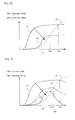
- Fig. 2 is a graph showing the relationship between the temperature of the NOx catalyst 5 versus the NOx reducing ability and the ammonia oxidizing ability of the NOx catalyst 5.
- the horizontal axis represents the temperature Tc of the NOx catalyst 5
- the vertical axis represents the NOx reducing ability or the ammonia oxidizing ability of the NOx catalyst 5.
- solid curves L1 and L2 represent the NOx reducing ability of the NOx catalyst 5.
- Solid curve L1 represents the NOx reducing ability of the NOx catalyst 5 in an initial condition.
- Solid curve L2 represents the NOx reducing ability of the NOx catalyst 5 in a deteriorated condition.
- the initial condition refers to a condition in which the degree of deterioration of the NOx catalyst 5 is substantially equal to that at the time when the NOx catalyst was installed in the vehicle, namely a condition in which heat deterioration of the NOx catalyst 5 has progressed little.
- the arrow in Fig. 2 indicates the direction of shift of the NOx reducing ability with the progress of the deterioration of the NOx catalyst 5.
- Broken curve L3 in Fig. 2 represents the ammonia oxidizing ability of the NOx catalyst 5.
- Fig. 3 is a graph showing the relationship between the temperature of the NOx catalyst 5 versus the NOx purification rate in the NOx catalyst 5.
- the horizontal axis represents the temperature Tc of the NOx catalyst 5
- the vertical axis represents the NOx purification rate in the NOx catalyst 5 or the ammonia oxidation ability of the NOx catalyst 5.
- solid curves L4, L5 and the chain double-dashed curve L0 represents the NOx purification rate in the NOx catalyst 5.
- Solid curve L1 represents the NOx purification rate in the NOx catalyst 5 in the initial condition.
- Solid curve L2 represents the NOx purification rate in the NOx catalyst 5 in a deteriorated condition.
- Chain double-dashed curve L0 represents the NOx purification rate in a condition in which the degree of deterioration of the NOx catalyst 5 is at the upper limit of the allowable range.
- the arrow in Fig. 3 indicates the direction of shift of the NOx purification rate with the progress in the deterioration of the NOx catalyst 5.
- Broken curve L3 in Fig. 3 represents the ammonia oxidizing ability of the NOx catalyst 5 as with that in Fig. 2 .
- the NOx reducing ability and the ammonia oxidizing ability of the NOx catalyst 5 are both enhanced as the temperature of the NOx catalyst 5 rises. While the temperature of the NOx catalyst 5 is relatively low, the NOx reducing ability is higher than the ammonia oxidizing ability. When the temperature of the NOx catalyst 5 exceeds a certain temperature, the ammonia oxidizing ability becomes higher than the NOx reducing ability.
- the NOx reducing ability of the NOx catalyst 5 is degraded as the deterioration of the NOx catalyst 5 progresses.
- the NOx reducing ability of the NOx catalyst 5 is lower when the degree of deterioration of the NOx catalyst 5 is high than when the degree of deterioration of the NOx catalyst 5 is low.
- the NOx reducing ability of the NOx catalyst 5 in relation to the temperature shifts in the direction indicated by the arrow in Fig. 2 (i.e. in the direction from solid curve L1 to solid curve L2) in accordance with the increase in the degree of deterioration of the NOx catalyst 5.
- the ammonia oxidizing ability of the NOx catalyst 5 is hard to be degraded even if the deterioration of the NOx catalyst 5 progresses. Therefore, provided that the temperature of the NOx catalyst 5 is the same, the ammonia oxidizing ability of the NOx catalyst 5 will be the same irrespective of the degree of deterioration of the NOx catalyst 5. In consequence, even when the deterioration of the NOx catalyst 5 progresses, the relationship between the temperature of the NOx catalyst 5 and the ammonia oxidizing ability of the NOx catalyst 5 represented by broken curve L3 in Fig. 2 is maintained.
- the oxidation of ammonia generates NOx. Therefore, if the ammonia oxidizing ability of the NOx catalyst 5 becomes higher than its NOx reducing ability, the quantity of NOx flowing out of the NOx catalyst 5 will increase, namely the NOx purification rate in the NOx catalyst 5 will decrease. Consequently, when the temperature of the NOx catalyst 5 reaches the temperature at which the ammonia oxidizing ability exceeds the NOx reducing ability, the NOx purification rate starts to decrease with a rise in the temperature of the NOx catalyst.
- the temperature of the NOx catalyst at which the ammonia oxidizing ability exceeds the NOx reducing ability is Tc1. If the NOx catalyst 5 is deteriorated, the temperature of the NOx catalyst at which the ammonia oxidizing ability exceeds the NOx reducing ability is Tc2. Therefore, if the NOx catalyst 5 is in the initial condition, the NOx purification rate starts to decrease as the temperature of the NOx catalyst 5 reaches Tc1, as will be seen from Fig. 3 . On the other hand, if the NOx catalyst 5 is deteriorated, the NOx purification rate starts to decrease as the temperature of the NOx catalyst 5 reaches Tc2.
- temperature Tc2 is lower than temperature Tc1. Therefore, the higher the degree of deterioration of the NOx catalyst 5 is, the lower the temperature (which will be hereinafter referred to as the NOx purification rate decrease temperature) at which the NOx purification rate starts to decrease with a rise in the temperature of the NOx catalyst 5 is.
- the NOx catalyst 5 is deteriorated if the degree of deterioration of the NOx catalyst 5 is higher than the upper limit of the allowable range.
- Tc0 be the NOx purification rate decrease temperature in the case where the degree of deterioration of the NOx catalyst 5 is at the upper limit of the allowable range, as shown in Fig. 3 .
- a determination is made as to whether the NOx catalyst 5 is deteriorated or not based on the NOx purification rate in the NOx catalyst 5 at a time when the temperature of the NOx catalyst 5 is higher than Tc0.
- the difference between the NOx purification rate at that time (i.e. the NOx purification rate in the NOx catalyst 5 in a deteriorated condition) and the NOx purification rate in the NOx catalyst 5 in a normal condition is larger than that at times when the temperature of the NOx catalyst 5 is not higher than the NOx purification rate decrease temperature corresponding to the degree of deterioration at the time.
- determination errors can be prevented by making a determination as to deterioration of the NOx catalyst 5 based on the NOx purification rate at a time when the temperature of the NOx catalyst 5 falls within a temperature range in which the difference between the NOx purification rate in the NOx catalyst 5 in a normal condition and the NOx purification rate in the NOx catalyst 5 in a deteriorated condition is relatively large.
- the method of detecting deterioration of the NOx catalyst according to this embodiment can provide more accurate detection of deterioration of the NOx catalyst 5.
- This process is stored in the ECU 10 in advance and executed repeatedly by the ECU 10 at regular intervals while aqueous solution of urea is added through the urea addition valve 7.
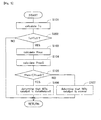
- step S101 the temperature Tc of the NOx catalyst 5 is calculated.
- the temperature of he NOx catalyst 5 can be calculated based on the measurement value of the temperature sensor 8.
- the temperature of the NOx catalyst 5 may be estimated based on the operation state (the engine load and engine speed etc.) of the internal combustion engine 1.
- the temperature of the NOx catalyst 5 can be calculated based on the measurement value of this temperature sensor.
- a temperature sensor may be provided in the NOx catalyst 5, and the temperature of the NOx catalyst 5 may be measured by this temperature sensor.
- step S102 it is determined whether or not the temperature Tc of the NOx catalyst 5 is higher than the NOx purification rate decrease temperature Tc0 with the NOx catalyst 5 of which the degree of deterioration is at the upper limit of the allowable range (or the NOx purification rate decrease temperature Tc0 that the NOx catalyst 5 will have when the degree of deterioration thereof is at the upper limit of the allowable range).
- the NOx purification rate decrease temperature Tc0 with the NOx catalyst 5 of which the degree of deterioration is at the upper limit of the allowable range has been obtained in advance by, for example, an experiment and stored in the ECU 10.
- step S102 determines whether the NOx purification rate Pnox in the NOx catalyst 5 is calculated next in step S103.
- the NOx purification rate Pnox in the NOx catalyst 5 is calculated based on the NOx concentration in the exhaust gas flowing into the NOx catalyst 5 and the NOx concentration in the exhaust gas flowing out of the NOx catalyst 5.
- the NOx concentration in the exhaust gas flowing into the NOx catalyst 5 can be estimated based on the operation state of the internal combustion engine 1.
- an NOx sensor may be provided in the exhaust passage 2 upstream of the NOx catalyst 5, and the NOx concentration in the exhaust gas flowing into the NOx catalyst 5 may be measured by this NOx sensor.
- the NOx concentration of the exhaust gas flowing out of the NOx catalyst 5 can be measured by the NOx sensor 9.
- step S104 the NOx purification rate at the time when the degree of deterioration of the NOx catalyst 5 is at the upper limit of the allowable range and the NOx catalyst 5 has the temperature Tc calculated in step S101 is calculated, namely the threshold value of the NOx purification rate Pnox0 (which will be hereinafter referred to as the normality determination threshold value) that allows the determination that the NOx catalyst 5 is in a normal condition is calculated.
- the relationship between the NOx purification rate and the temperature of the NOx catalyst 5 at the time when the degree of deterioration of the NOx catalyst 5 is at the upper limit of the allowable range is stored in the ECU 10 in advance as a map like that shown in Fig. 3 (the chain double-dashed curve in Fig. 3 ) or as a function.
- the normality determination threshold value Pnox0 is calculated using this map or function.
- step S105 it is determined whether or not the NOx purification rate Pnox calculated in step S103 is lower than the normality determination threshold value Pnox0 calculated in step S104. If the determination in step S105 is affirmative, it is determined next in step S106 that the NOx catalyst 5 is deteriorated. On the other hand, if the determination in step S105 is negative, it is determined next in step S107 that the NOx catalyst 5 is in a normal condition.
- the NOx purification rate decreases with a rise in the temperature of the NOx catalyst 5 when the temperature of the NOx catalyst 5 exceeds the NOx purification rate decrease temperature Tc1 with the NOx catalyst 5 that is in the initial condition. Consequently, the difference between the NOx purification rate in the NOx catalyst 5 in a normal condition and the NOx purification rate in the NOx catalyst 5 in a deteriorated condition decreases gradually with a rise in the temperature of the NOx catalyst 5.
- the determination as to deterioration of the NOx catalyst 5 is performed at a time when the temperature of the NOx catalyst 5 is equal to the NOx purification rate decrease temperature Tc1 with the NOx catalyst 5 that is in the initial condition, the determination as to deterioration of the NOx catalyst 5 can be performed at the time when the difference between the NOx purification rate in the NOx catalyst 5 in a normal condition and the NOx purification rate in the NOx catalyst 5 in a deteriorated condition is as large as possible. In consequence, deterioration of the NOx catalyst 5 can be detected with improved accuracy.
- step S202 it is determined whether or not the temperature Tc of the NOx catalyst 5 is equal to the NOx purification rate decrease temperature Tc1 with the NOx catalyst 5 that is in the initial condition.
- the NOx purification rate decrease temperature Tc1 with the NOx catalyst 5 that is in the initial condition has been determined in advance by, for example, an experiment and stored in the ECU 10.
- step S202 determines whether the execution of this process is once terminated. If the determination in step S202 is affirmative, the processing of step S103 is executed next.
- the NOx purification rate decreases with the rise in the temperature.
- the NOx purification rate becomes zero when the temperature of the NOx catalyst 5 reaches a certain temperature Tc3.
- the NOx purification rate is zero if the NOx catalyst 5 is deteriorated.
- the NOx purification rate starts to decrease with a rise in the temperature of the NOx catalyst 5 as the temperature of the NOx catalyst 5 rises beyond the NOx purification rate decrease temperature Tc0 with the NOx catalyst 5 of which the degree of deterioration is at the upper limit of the allowable range to reach the NOx purification rate decrease temperature corresponding to the actual degree of deterioration of the NOx catalyst 5.
- the NOx purification rate In the temperature range in which the NOx purification rate is zero when the degree of deterioration of the NOx catalyst is higher than the upper limit of the allowable range (namely, when the NOx catalyst is deteriorated), and the NOx purification rate decreases with a rise in the temperature of the NOx catalyst 5 when the degree of deterioration of the NOx catalyst 5 is lower than the upper limit of the allowable range (namely, when the NOx catalyst is in a normal condition), namely in the range of the temperature of the NOx catalyst 5 higher than Tc3, the difference between the NOx purification rate in the NOx catalyst 5 in a normal condition and the NOx purification rate in the NOx catalyst 5 in a deteriorated condition gradually decreases as the temperature of the NOx catalyst 5 rises.
- the determination as to deterioration of the NOx catalyst 5 is performed at a time when the temperature of the NOx catalyst 5 is higher than the NOx purification rate decrease temperature Tc0 with the NOx catalyst 5 of which the degree of deterioration is at the upper limit of the allowable range and not higher than the temperature Tc3 at which the NOx purification rate in the NOx catalyst 5 of which the degree of deterioration is at the upper limit of the allowable range will become zero, the determination as to deterioration of the NOx catalyst 5 can be performed at the time when the difference between the NOx purification rate in the NOx catalyst 5 in a normal condition and the NOx purification rate in the NOx catalyst 5 in a deteriorated condition is as large as possible. In consequence, deterioration of the NOx catalyst 5 can be detected with improved accuracy.
- step S303 it is determined whether or not the temperature of the NOx catalyst 5 is equal to or lower than the temperature Tc3 at which the NOx purification rate in the NOx catalyst 5 of which the degree of deterioration is at the upper limit of the allowable range will become zero.
- the temperature Tc3 at which the NOx purification rate in the NOx catalyst 5 of which the degree of deterioration is at the upper limit of the allowable range will become zero has been obtained in advance based on, for example, an experiment and stored in the ECU10.
- step S303 determines whether the execution of this process is once terminated. If the determination in step S303 is negative, the execution of this process is once terminated. On the other hand, if the determination in step S303 is affirmative, namely if the temperature of the NOx catalyst 5 is higher than Tc0 and not higher than Tc3, the processing of step S103 is executed next.
- the basic configuration of the exhaust system of the internal combustion engine according to this embodiment is the same as that in embodiment 1.
- the method of detecting deterioration of the NOx catalyst according to this embodiment will be described.
- a determination as to whether the NOx catalyst 5 is deteriorated or not is made based on the NOx purification rate decrease temperature. Specifically, if the NOx purification rate decrease temperature is lower than the NOx purification rate decrease temperature Tc0 with the NOx catalyst 5 of which the degree of deterioration is at the upper limit of the allowable range, it is determined that the NOx catalyst 5 is deteriorated.
- the NOx purification rate in the NOx catalyst 5 is calculated based on the NOx concentration in the exhaust gas flowing into the NOx catalyst 5 and the NOx concentration in the exhaust gas flowing out of the NOx catalyst 5.
- the NOx concentration in the exhaust gas flowing into the NOx catalyst 5 is estimated based on the operation state of the internal combustion engine 1.
- an NOx sensor may be provided in the exhaust passage 2 upstream of the NOx catalyst 5, and the NOx concentration in the exhaust gas flowing into the NOx catalyst 5 may be measured by this NOx sensor.
- the NOx concentration of the exhaust gas flowing out of the NOx catalyst 5 is measured by the NOx sensor 9.
- the value of the NOx purification rate calculated based on the NOx concentration will also have an error.
- the value of the NOx purification rate decrease temperature obtained based on the change in the NOx purification rate with the change in the temperature of the NOx catalyst 5 will not vary. Therefore, the determination of deterioration of the NOx catalyst 5 based on the NOx purification rate decrease temperature can provide more accurate detection of deterioration of the NOx catalyst 5.
- step S401 the temperature Tc of the NOx catalyst 5 is calculated in the manner same as step S101 in the process shown in Fig. 4 .
- step S402 the NOx purification rate Pnox in the NOx catalyst 5 is calculated in the same manner as step S103 in the process shown in Fig. 4 .
- the NOx purification rate Pnox calculated in step S402 is associated with the temperature Tc of the NOx catalyst 5 calculated in step S401 and stored in the ECU 10.
- the temperature Tc of the NOx catalyst 5 changes with the change in the temperature of the exhaust gas flowing into the NOx catalyst 5. Therefore, the relationship between the temperature Tc of the NOx catalyst 5 and the NOx purification rate Pnox like that shown in Fig. 3 can be obtained by calculating the temperature Tc of the NOx catalyst 5 and the NOx purification rate Pnox associated with the temperature and storing them for a certain period of time.
- the relationship between the temperature Tc of the NOx catalyst 5 and the NOx purification rate Pnox may be obtained by forcedly varying the temperature Tc of the NOx catalyst 5 and calculating NOx purification rates Pnox associated with different temperatures.
- step S403 the NOx purification rate decrease temperature Tcd is obtained based on the relationship between the temperature Tc of the NOx catalyst 5 and the NOx purification rate Pnox.
- the NOx purification rate decrease temperature Tcd obtained in this step is the NOx purification rate decrease temperature corresponding to the degree of deterioration of the NOx catalyst 5 at the time.
- step S404 it is determined whether or not the NOx purification rate decrease temperature Tcd obtained in step S403 is lower than the NOx purification rate decrease temperature Tc0 with the NOx catalyst 5 of which the degree of deterioration is at the upper limit of the allowable range.
- the NOx purification rate decrease temperature Tc0 with the NOx catalyst 5 of which the degree of deterioration is at the upper limit of the allowable range has been obtained in advance by, for example, an experiment and stored in the ECU 10.
- step S404 determines whether the NOx catalyst 5 is deteriorated. If the determination in step S404 is negative, it is determined next in step S406 that the NOx catalyst 5 is in a normal condition.
Landscapes
- Engineering & Computer Science (AREA)
- Chemical & Material Sciences (AREA)
- Chemical Kinetics & Catalysis (AREA)
- Combustion & Propulsion (AREA)
- Mechanical Engineering (AREA)
- General Engineering & Computer Science (AREA)
- Health & Medical Sciences (AREA)
- Toxicology (AREA)
- Life Sciences & Earth Sciences (AREA)
- Molecular Biology (AREA)
- Physics & Mathematics (AREA)
- Analytical Chemistry (AREA)
- Biochemistry (AREA)
- General Health & Medical Sciences (AREA)
- General Physics & Mathematics (AREA)
- Immunology (AREA)
- Pathology (AREA)
- Exhaust Gas After Treatment (AREA)
- Exhaust Gas Treatment By Means Of Catalyst (AREA)
Priority Applications (1)
| Application Number | Priority Date | Filing Date | Title |
|---|---|---|---|
| EP14199675.1A EP2896801B1 (de) | 2011-04-12 | 2011-04-12 | Vorrichtung zum Feststellen des Verschleisses eines Katalysators zur selektiven Reduktion von Stickstoffoxiden |
Applications Claiming Priority (3)
| Application Number | Priority Date | Filing Date | Title |
|---|---|---|---|
| EP11863657.0A EP2698513B1 (de) | 2011-04-12 | 2011-04-12 | Vorrichtung zum feststellen des verschleisses eines nox katalysators vom typ scr |
| PCT/JP2011/059092 WO2012140739A1 (ja) | 2011-04-12 | 2011-04-12 | 選択還元型NOx触媒の劣化検出装置 |
| EP14199675.1A EP2896801B1 (de) | 2011-04-12 | 2011-04-12 | Vorrichtung zum Feststellen des Verschleisses eines Katalysators zur selektiven Reduktion von Stickstoffoxiden |
Related Parent Applications (2)
| Application Number | Title | Priority Date | Filing Date |
|---|---|---|---|
| EP11863657.0A Division-Into EP2698513B1 (de) | 2011-04-12 | 2011-04-12 | Vorrichtung zum feststellen des verschleisses eines nox katalysators vom typ scr |
| EP11863657.0A Division EP2698513B1 (de) | 2011-04-12 | 2011-04-12 | Vorrichtung zum feststellen des verschleisses eines nox katalysators vom typ scr |
Publications (3)
| Publication Number | Publication Date |
|---|---|
| EP2896801A1 true EP2896801A1 (de) | 2015-07-22 |
| EP2896801A8 EP2896801A8 (de) | 2015-10-28 |
| EP2896801B1 EP2896801B1 (de) | 2017-02-22 |
Family
ID=47008946
Family Applications (2)
| Application Number | Title | Priority Date | Filing Date |
|---|---|---|---|
| EP11863657.0A Not-in-force EP2698513B1 (de) | 2011-04-12 | 2011-04-12 | Vorrichtung zum feststellen des verschleisses eines nox katalysators vom typ scr |
| EP14199675.1A Not-in-force EP2896801B1 (de) | 2011-04-12 | 2011-04-12 | Vorrichtung zum Feststellen des Verschleisses eines Katalysators zur selektiven Reduktion von Stickstoffoxiden |
Family Applications Before (1)
| Application Number | Title | Priority Date | Filing Date |
|---|---|---|---|
| EP11863657.0A Not-in-force EP2698513B1 (de) | 2011-04-12 | 2011-04-12 | Vorrichtung zum feststellen des verschleisses eines nox katalysators vom typ scr |
Country Status (5)
| Country | Link |
|---|---|
| US (1) | US9594065B2 (de) |
| EP (2) | EP2698513B1 (de) |
| JP (1) | JP5673803B2 (de) |
| CN (1) | CN103703221B (de) |
| WO (1) | WO2012140739A1 (de) |
Families Citing this family (6)
| Publication number | Priority date | Publication date | Assignee | Title |
|---|---|---|---|---|
| JP5892047B2 (ja) * | 2012-11-15 | 2016-03-23 | トヨタ自動車株式会社 | Scrシステムの劣化診断装置 |
| CN104884754B (zh) * | 2012-12-13 | 2017-11-14 | 丰田自动车株式会社 | 排气净化装置的故障诊断装置 |
| AT518521B1 (de) * | 2016-07-18 | 2017-11-15 | Avl List Gmbh | Verfahren zur erkennung einer undichten stelle in einem wärmerückgewinnungssystem |
| JP6520971B2 (ja) * | 2017-03-02 | 2019-05-29 | トヨタ自動車株式会社 | 内燃機関の排気浄化装置 |
| JP6536623B2 (ja) * | 2017-05-26 | 2019-07-03 | トヨタ自動車株式会社 | NOx吸蔵還元触媒の劣化診断装置 |
| JP6729542B2 (ja) * | 2017-12-27 | 2020-07-22 | トヨタ自動車株式会社 | 排気浄化装置の異常診断システム |
Citations (5)
| Publication number | Priority date | Publication date | Assignee | Title |
|---|---|---|---|---|
| FR2883922A1 (fr) * | 2005-03-31 | 2006-10-06 | Bosch Gmbh Robert | Procede de gestion d'un moteur a combustion interne et dispositif pour la mise en oeuvre du procede |
| JP2008144711A (ja) | 2006-12-12 | 2008-06-26 | Toyota Motor Corp | NOx触媒の異常診断装置及び異常診断方法 |
| JP2009127496A (ja) | 2007-11-21 | 2009-06-11 | Toyota Motor Corp | NOx浄化装置における診断方法および診断装置 |
| EP2108793A1 (de) * | 2007-02-02 | 2009-10-14 | Bosch Corporation | Versagensdiagnosevorrichtung für abgasreinigungssystem und versagensdiagnoseverfahren für abgasreinigungssystem |
| US20110061372A1 (en) * | 2009-09-14 | 2011-03-17 | Gm Global Technology Operations, Inc. | Intrusive scr efficency testing systems and methods for vehicles with low temperature exhaust gas |
Family Cites Families (8)
| Publication number | Priority date | Publication date | Assignee | Title |
|---|---|---|---|---|
| JPH10259713A (ja) * | 1997-03-18 | 1998-09-29 | Denso Corp | 内燃機関の排気浄化装置 |
| JP4729518B2 (ja) * | 2007-03-07 | 2011-07-20 | トヨタ自動車株式会社 | NOx触媒の劣化診断装置 |
| JP4665923B2 (ja) * | 2007-03-13 | 2011-04-06 | トヨタ自動車株式会社 | 触媒劣化判定装置 |
| JP4767218B2 (ja) * | 2007-06-08 | 2011-09-07 | 本田技研工業株式会社 | 内燃機関の排ガス浄化装置 |
| JP4274270B2 (ja) * | 2007-06-26 | 2009-06-03 | いすゞ自動車株式会社 | NOx浄化システム及びNOx浄化システムの制御方法 |
| JP4412399B2 (ja) * | 2007-12-06 | 2010-02-10 | トヨタ自動車株式会社 | 内燃機関の異常検出装置 |
| CN101918686B (zh) * | 2009-03-31 | 2012-12-26 | 丰田自动车株式会社 | 催化剂劣化判定装置及催化剂劣化判定方法 |
| JP5182200B2 (ja) * | 2009-04-10 | 2013-04-10 | トヨタ自動車株式会社 | 触媒劣化判定装置及び触媒劣化判定方法 |
-
2011
- 2011-04-12 CN CN201180070057.3A patent/CN103703221B/zh not_active Expired - Fee Related
- 2011-04-12 EP EP11863657.0A patent/EP2698513B1/de not_active Not-in-force
- 2011-04-12 WO PCT/JP2011/059092 patent/WO2012140739A1/ja not_active Ceased
- 2011-04-12 JP JP2013509696A patent/JP5673803B2/ja not_active Expired - Fee Related
- 2011-04-12 US US14/110,636 patent/US9594065B2/en not_active Expired - Fee Related
- 2011-04-12 EP EP14199675.1A patent/EP2896801B1/de not_active Not-in-force
Patent Citations (5)
| Publication number | Priority date | Publication date | Assignee | Title |
|---|---|---|---|---|
| FR2883922A1 (fr) * | 2005-03-31 | 2006-10-06 | Bosch Gmbh Robert | Procede de gestion d'un moteur a combustion interne et dispositif pour la mise en oeuvre du procede |
| JP2008144711A (ja) | 2006-12-12 | 2008-06-26 | Toyota Motor Corp | NOx触媒の異常診断装置及び異常診断方法 |
| EP2108793A1 (de) * | 2007-02-02 | 2009-10-14 | Bosch Corporation | Versagensdiagnosevorrichtung für abgasreinigungssystem und versagensdiagnoseverfahren für abgasreinigungssystem |
| JP2009127496A (ja) | 2007-11-21 | 2009-06-11 | Toyota Motor Corp | NOx浄化装置における診断方法および診断装置 |
| US20110061372A1 (en) * | 2009-09-14 | 2011-03-17 | Gm Global Technology Operations, Inc. | Intrusive scr efficency testing systems and methods for vehicles with low temperature exhaust gas |
Also Published As
| Publication number | Publication date |
|---|---|
| JP5673803B2 (ja) | 2015-02-18 |
| JPWO2012140739A1 (ja) | 2014-07-28 |
| EP2698513B1 (de) | 2016-10-19 |
| US9594065B2 (en) | 2017-03-14 |
| EP2896801B1 (de) | 2017-02-22 |
| EP2896801A8 (de) | 2015-10-28 |
| US20140050623A1 (en) | 2014-02-20 |
| EP2698513A4 (de) | 2015-03-18 |
| WO2012140739A1 (ja) | 2012-10-18 |
| CN103703221A (zh) | 2014-04-02 |
| EP2698513A1 (de) | 2014-02-19 |
| CN103703221B (zh) | 2016-03-16 |
Similar Documents
| Publication | Publication Date | Title |
|---|---|---|
| EP2415983B1 (de) | Vorrichtung zur bestimmung des verschleisses eines katalysators und verfahren zur bestimmung des verschleisses eines katalysators | |
| US9550149B2 (en) | Exhaust gas purification apparatus for internal combustion engine | |
| EP2851530B1 (de) | Abgassteuerungsvorrichtung und Steuerungsverfahren für Abgassteuerungsvorrichtung | |
| US8201397B2 (en) | Exhaust gas purification device of internal combustion engine | |
| EP2896801B1 (de) | Vorrichtung zum Feststellen des Verschleisses eines Katalysators zur selektiven Reduktion von Stickstoffoxiden | |
| EP2878782A1 (de) | Vorrichtung zur diagnose von anomalien und abgasreinigungsvorrichtung eines verbrennungsmotors | |
| EP2730759A1 (de) | Abgasreinigungsvorrichtung für einen verbrennungsmotor | |
| US8806928B2 (en) | Catalyst deterioration detection apparatus and catalyst deterioration detection method for internal combustion engine | |
| US9056278B2 (en) | Exhaust gas purification apparatus for an internal combustion engine | |
| JP5182200B2 (ja) | 触媒劣化判定装置及び触媒劣化判定方法 | |
| EP2759684B1 (de) | Abgasreinigungsvorrichtung für einen verbrennungsmotor | |
| US9382830B2 (en) | Exhaust gas purification apparatus for an internal combustion engine | |
| EP2865857B1 (de) | Abgasreinigungsvorrichtung für einen verbrennungsmotor | |
| JP2014181668A (ja) | 内燃機関の排気浄化システム | |
| JP2012233463A (ja) | 排気浄化システムの故障検出装置 | |
| JP2012112318A (ja) | 内燃機関の触媒劣化検出装置 | |
| JP2013087652A (ja) | 内燃機関の排気浄化装置 |
Legal Events
| Date | Code | Title | Description |
|---|---|---|---|
| PUAI | Public reference made under article 153(3) epc to a published international application that has entered the european phase |
Free format text: ORIGINAL CODE: 0009012 |
|
| 17P | Request for examination filed |
Effective date: 20141222 |
|
| AC | Divisional application: reference to earlier application |
Ref document number: 2698513 Country of ref document: EP Kind code of ref document: P |
|
| AK | Designated contracting states |
Kind code of ref document: A1 Designated state(s): AL AT BE BG CH CY CZ DE DK EE ES FI FR GB GR HR HU IE IS IT LI LT LU LV MC MK MT NL NO PL PT RO RS SE SI SK SM TR |
|
| RAP1 | Party data changed (applicant data changed or rights of an application transferred) |
Owner name: TOYOTA JIDOSHA KABUSHIKI KAISHA |
|
| RIN1 | Information on inventor provided before grant (corrected) |
Inventor name: HAGIMOTO, TAIGA Inventor name: SHIBATA, DAISUKE |
|
| RIN1 | Information on inventor provided before grant (corrected) |
Inventor name: SHIBATA, DAISUKE Inventor name: HAGIMOTO, TAIGA |
|
| 17P | Request for examination filed |
Effective date: 20160122 |
|
| RBV | Designated contracting states (corrected) |
Designated state(s): AL AT BE BG CH CY CZ DE DK EE ES FI FR GB GR HR HU IE IS IT LI LT LU LV MC MK MT NL NO PL PT RO RS SE SI SK SM TR |
|
| GRAP | Despatch of communication of intention to grant a patent |
Free format text: ORIGINAL CODE: EPIDOSNIGR1 |
|
| INTG | Intention to grant announced |
Effective date: 20160805 |
|
| STAA | Information on the status of an ep patent application or granted ep patent |
Free format text: STATUS: GRANT OF PATENT IS INTENDED |
|
| GRAS | Grant fee paid |
Free format text: ORIGINAL CODE: EPIDOSNIGR3 |
|
| GRAA | (expected) grant |
Free format text: ORIGINAL CODE: 0009210 |
|
| STAA | Information on the status of an ep patent application or granted ep patent |
Free format text: STATUS: THE PATENT HAS BEEN GRANTED |
|
| AC | Divisional application: reference to earlier application |
Ref document number: 2698513 Country of ref document: EP Kind code of ref document: P |
|
| AK | Designated contracting states |
Kind code of ref document: B1 Designated state(s): AL AT BE BG CH CY CZ DE DK EE ES FI FR GB GR HR HU IE IS IT LI LT LU LV MC MK MT NL NO PL PT RO RS SE SI SK SM TR |
|
| REG | Reference to a national code |
Ref country code: GB Ref legal event code: FG4D |
|
| REG | Reference to a national code |
Ref country code: CH Ref legal event code: EP |
|
| REG | Reference to a national code |
Ref country code: AT Ref legal event code: REF Ref document number: 869456 Country of ref document: AT Kind code of ref document: T Effective date: 20170315 |
|
| REG | Reference to a national code |
Ref country code: IE Ref legal event code: FG4D |
|
| REG | Reference to a national code |
Ref country code: FR Ref legal event code: PLFP Year of fee payment: 7 |
|
| REG | Reference to a national code |
Ref country code: DE Ref legal event code: R096 Ref document number: 602011035336 Country of ref document: DE |
|
| REG | Reference to a national code |
Ref country code: LT Ref legal event code: MG4D |
|
| REG | Reference to a national code |
Ref country code: NL Ref legal event code: MP Effective date: 20170222 |
|
| REG | Reference to a national code |
Ref country code: AT Ref legal event code: MK05 Ref document number: 869456 Country of ref document: AT Kind code of ref document: T Effective date: 20170222 |
|
| PG25 | Lapsed in a contracting state [announced via postgrant information from national office to epo] |
Ref country code: FI Free format text: LAPSE BECAUSE OF FAILURE TO SUBMIT A TRANSLATION OF THE DESCRIPTION OR TO PAY THE FEE WITHIN THE PRESCRIBED TIME-LIMIT Effective date: 20170222 Ref country code: LT Free format text: LAPSE BECAUSE OF FAILURE TO SUBMIT A TRANSLATION OF THE DESCRIPTION OR TO PAY THE FEE WITHIN THE PRESCRIBED TIME-LIMIT Effective date: 20170222 Ref country code: GR Free format text: LAPSE BECAUSE OF FAILURE TO SUBMIT A TRANSLATION OF THE DESCRIPTION OR TO PAY THE FEE WITHIN THE PRESCRIBED TIME-LIMIT Effective date: 20170523 Ref country code: NO Free format text: LAPSE BECAUSE OF FAILURE TO SUBMIT A TRANSLATION OF THE DESCRIPTION OR TO PAY THE FEE WITHIN THE PRESCRIBED TIME-LIMIT Effective date: 20170522 Ref country code: HR Free format text: LAPSE BECAUSE OF FAILURE TO SUBMIT A TRANSLATION OF THE DESCRIPTION OR TO PAY THE FEE WITHIN THE PRESCRIBED TIME-LIMIT Effective date: 20170222 |
|
| PG25 | Lapsed in a contracting state [announced via postgrant information from national office to epo] |
Ref country code: AT Free format text: LAPSE BECAUSE OF FAILURE TO SUBMIT A TRANSLATION OF THE DESCRIPTION OR TO PAY THE FEE WITHIN THE PRESCRIBED TIME-LIMIT Effective date: 20170222 Ref country code: RS Free format text: LAPSE BECAUSE OF FAILURE TO SUBMIT A TRANSLATION OF THE DESCRIPTION OR TO PAY THE FEE WITHIN THE PRESCRIBED TIME-LIMIT Effective date: 20170222 Ref country code: PT Free format text: LAPSE BECAUSE OF FAILURE TO SUBMIT A TRANSLATION OF THE DESCRIPTION OR TO PAY THE FEE WITHIN THE PRESCRIBED TIME-LIMIT Effective date: 20170622 Ref country code: BG Free format text: LAPSE BECAUSE OF FAILURE TO SUBMIT A TRANSLATION OF THE DESCRIPTION OR TO PAY THE FEE WITHIN THE PRESCRIBED TIME-LIMIT Effective date: 20170522 Ref country code: ES Free format text: LAPSE BECAUSE OF FAILURE TO SUBMIT A TRANSLATION OF THE DESCRIPTION OR TO PAY THE FEE WITHIN THE PRESCRIBED TIME-LIMIT Effective date: 20170222 Ref country code: LV Free format text: LAPSE BECAUSE OF FAILURE TO SUBMIT A TRANSLATION OF THE DESCRIPTION OR TO PAY THE FEE WITHIN THE PRESCRIBED TIME-LIMIT Effective date: 20170222 Ref country code: NL Free format text: LAPSE BECAUSE OF FAILURE TO SUBMIT A TRANSLATION OF THE DESCRIPTION OR TO PAY THE FEE WITHIN THE PRESCRIBED TIME-LIMIT Effective date: 20170222 Ref country code: SE Free format text: LAPSE BECAUSE OF FAILURE TO SUBMIT A TRANSLATION OF THE DESCRIPTION OR TO PAY THE FEE WITHIN THE PRESCRIBED TIME-LIMIT Effective date: 20170222 |
|
| PG25 | Lapsed in a contracting state [announced via postgrant information from national office to epo] |
Ref country code: CZ Free format text: LAPSE BECAUSE OF FAILURE TO SUBMIT A TRANSLATION OF THE DESCRIPTION OR TO PAY THE FEE WITHIN THE PRESCRIBED TIME-LIMIT Effective date: 20170222 Ref country code: EE Free format text: LAPSE BECAUSE OF FAILURE TO SUBMIT A TRANSLATION OF THE DESCRIPTION OR TO PAY THE FEE WITHIN THE PRESCRIBED TIME-LIMIT Effective date: 20170222 Ref country code: RO Free format text: LAPSE BECAUSE OF FAILURE TO SUBMIT A TRANSLATION OF THE DESCRIPTION OR TO PAY THE FEE WITHIN THE PRESCRIBED TIME-LIMIT Effective date: 20170222 Ref country code: SK Free format text: LAPSE BECAUSE OF FAILURE TO SUBMIT A TRANSLATION OF THE DESCRIPTION OR TO PAY THE FEE WITHIN THE PRESCRIBED TIME-LIMIT Effective date: 20170222 |
|
| REG | Reference to a national code |
Ref country code: DE Ref legal event code: R097 Ref document number: 602011035336 Country of ref document: DE |
|
| PG25 | Lapsed in a contracting state [announced via postgrant information from national office to epo] |
Ref country code: PL Free format text: LAPSE BECAUSE OF FAILURE TO SUBMIT A TRANSLATION OF THE DESCRIPTION OR TO PAY THE FEE WITHIN THE PRESCRIBED TIME-LIMIT Effective date: 20170222 Ref country code: SM Free format text: LAPSE BECAUSE OF FAILURE TO SUBMIT A TRANSLATION OF THE DESCRIPTION OR TO PAY THE FEE WITHIN THE PRESCRIBED TIME-LIMIT Effective date: 20170222 Ref country code: DK Free format text: LAPSE BECAUSE OF FAILURE TO SUBMIT A TRANSLATION OF THE DESCRIPTION OR TO PAY THE FEE WITHIN THE PRESCRIBED TIME-LIMIT Effective date: 20170222 |
|
| REG | Reference to a national code |
Ref country code: CH Ref legal event code: PL |
|
| PLBE | No opposition filed within time limit |
Free format text: ORIGINAL CODE: 0009261 |
|
| STAA | Information on the status of an ep patent application or granted ep patent |
Free format text: STATUS: NO OPPOSITION FILED WITHIN TIME LIMIT |
|
| REG | Reference to a national code |
Ref country code: DE Ref legal event code: R084 Ref document number: 602011035336 Country of ref document: DE |
|
| GBPC | Gb: european patent ceased through non-payment of renewal fee |
Effective date: 20170522 |
|
| REG | Reference to a national code |
Ref country code: IE Ref legal event code: MM4A |
|
| 26N | No opposition filed |
Effective date: 20171123 |
|
| PG25 | Lapsed in a contracting state [announced via postgrant information from national office to epo] |
Ref country code: MC Free format text: LAPSE BECAUSE OF FAILURE TO SUBMIT A TRANSLATION OF THE DESCRIPTION OR TO PAY THE FEE WITHIN THE PRESCRIBED TIME-LIMIT Effective date: 20170222 |
|
| PG25 | Lapsed in a contracting state [announced via postgrant information from national office to epo] |
Ref country code: LU Free format text: LAPSE BECAUSE OF NON-PAYMENT OF DUE FEES Effective date: 20170412 Ref country code: LI Free format text: LAPSE BECAUSE OF NON-PAYMENT OF DUE FEES Effective date: 20170430 Ref country code: SI Free format text: LAPSE BECAUSE OF FAILURE TO SUBMIT A TRANSLATION OF THE DESCRIPTION OR TO PAY THE FEE WITHIN THE PRESCRIBED TIME-LIMIT Effective date: 20170222 Ref country code: CH Free format text: LAPSE BECAUSE OF NON-PAYMENT OF DUE FEES Effective date: 20170430 |
|
| REG | Reference to a national code |
Ref country code: FR Ref legal event code: PLFP Year of fee payment: 8 |
|
| REG | Reference to a national code |
Ref country code: BE Ref legal event code: MM Effective date: 20170430 |
|
| PG25 | Lapsed in a contracting state [announced via postgrant information from national office to epo] |
Ref country code: GB Free format text: LAPSE BECAUSE OF NON-PAYMENT OF DUE FEES Effective date: 20170522 Ref country code: IE Free format text: LAPSE BECAUSE OF NON-PAYMENT OF DUE FEES Effective date: 20170412 |
|
| PG25 | Lapsed in a contracting state [announced via postgrant information from national office to epo] |
Ref country code: BE Free format text: LAPSE BECAUSE OF NON-PAYMENT OF DUE FEES Effective date: 20170430 |
|
| PG25 | Lapsed in a contracting state [announced via postgrant information from national office to epo] |
Ref country code: MT Free format text: LAPSE BECAUSE OF NON-PAYMENT OF DUE FEES Effective date: 20170412 |
|
| PGFP | Annual fee paid to national office [announced via postgrant information from national office to epo] |
Ref country code: FR Payment date: 20190313 Year of fee payment: 9 |
|
| PG25 | Lapsed in a contracting state [announced via postgrant information from national office to epo] |
Ref country code: HU Free format text: LAPSE BECAUSE OF FAILURE TO SUBMIT A TRANSLATION OF THE DESCRIPTION OR TO PAY THE FEE WITHIN THE PRESCRIBED TIME-LIMIT; INVALID AB INITIO Effective date: 20110412 |
|
| PGFP | Annual fee paid to national office [announced via postgrant information from national office to epo] |
Ref country code: DE Payment date: 20190402 Year of fee payment: 9 Ref country code: IT Payment date: 20190419 Year of fee payment: 9 |
|
| PG25 | Lapsed in a contracting state [announced via postgrant information from national office to epo] |
Ref country code: CY Free format text: LAPSE BECAUSE OF FAILURE TO SUBMIT A TRANSLATION OF THE DESCRIPTION OR TO PAY THE FEE WITHIN THE PRESCRIBED TIME-LIMIT Effective date: 20170222 |
|
| PG25 | Lapsed in a contracting state [announced via postgrant information from national office to epo] |
Ref country code: MK Free format text: LAPSE BECAUSE OF FAILURE TO SUBMIT A TRANSLATION OF THE DESCRIPTION OR TO PAY THE FEE WITHIN THE PRESCRIBED TIME-LIMIT Effective date: 20170222 |
|
| PG25 | Lapsed in a contracting state [announced via postgrant information from national office to epo] |
Ref country code: TR Free format text: LAPSE BECAUSE OF FAILURE TO SUBMIT A TRANSLATION OF THE DESCRIPTION OR TO PAY THE FEE WITHIN THE PRESCRIBED TIME-LIMIT Effective date: 20170222 |
|
| PG25 | Lapsed in a contracting state [announced via postgrant information from national office to epo] |
Ref country code: AL Free format text: LAPSE BECAUSE OF FAILURE TO SUBMIT A TRANSLATION OF THE DESCRIPTION OR TO PAY THE FEE WITHIN THE PRESCRIBED TIME-LIMIT Effective date: 20170222 Ref country code: IS Free format text: LAPSE BECAUSE OF FAILURE TO SUBMIT A TRANSLATION OF THE DESCRIPTION OR TO PAY THE FEE WITHIN THE PRESCRIBED TIME-LIMIT Effective date: 20170622 |
|
| REG | Reference to a national code |
Ref country code: DE Ref legal event code: R119 Ref document number: 602011035336 Country of ref document: DE |
|
| PG25 | Lapsed in a contracting state [announced via postgrant information from national office to epo] |
Ref country code: FR Free format text: LAPSE BECAUSE OF NON-PAYMENT OF DUE FEES Effective date: 20200430 Ref country code: DE Free format text: LAPSE BECAUSE OF NON-PAYMENT OF DUE FEES Effective date: 20201103 |
|
| PG25 | Lapsed in a contracting state [announced via postgrant information from national office to epo] |
Ref country code: IT Free format text: LAPSE BECAUSE OF NON-PAYMENT OF DUE FEES Effective date: 20200412 |