EP2897009A1 - Procédé d'optimisation de séquence de production et système d'optimisation de séquence de production - Google Patents
Procédé d'optimisation de séquence de production et système d'optimisation de séquence de production Download PDFInfo
- Publication number
- EP2897009A1 EP2897009A1 EP12884735.7A EP12884735A EP2897009A1 EP 2897009 A1 EP2897009 A1 EP 2897009A1 EP 12884735 A EP12884735 A EP 12884735A EP 2897009 A1 EP2897009 A1 EP 2897009A1
- Authority
- EP
- European Patent Office
- Prior art keywords
- feeders
- group
- production
- resources
- electronic component
- Prior art date
- Legal status (The legal status is an assumption and is not a legal conclusion. Google has not performed a legal analysis and makes no representation as to the accuracy of the status listed.)
- Granted
Links
Images




Classifications
-
- G—PHYSICS
- G05—CONTROLLING; REGULATING
- G05B—CONTROL OR REGULATING SYSTEMS IN GENERAL; FUNCTIONAL ELEMENTS OF SUCH SYSTEMS; MONITORING OR TESTING ARRANGEMENTS FOR SUCH SYSTEMS OR ELEMENTS
- G05B19/00—Program-control systems
- G05B19/02—Program-control systems electric
- G05B19/418—Total factory control, i.e. centrally controlling a plurality of machines, e.g. direct or distributed numerical control [DNC], flexible manufacturing systems [FMS], integrated manufacturing systems [IMS] or computer integrated manufacturing [CIM]
- G05B19/41865—Total factory control, i.e. centrally controlling a plurality of machines, e.g. direct or distributed numerical control [DNC], flexible manufacturing systems [FMS], integrated manufacturing systems [IMS] or computer integrated manufacturing [CIM] characterised by job scheduling, process planning, material flow
-
- G—PHYSICS
- G06—COMPUTING OR CALCULATING; COUNTING
- G06F—ELECTRIC DIGITAL DATA PROCESSING
- G06F9/00—Arrangements for program control, e.g. control units
- G06F9/06—Arrangements for program control, e.g. control units using stored programs, i.e. using an internal store of processing equipment to receive or retain programs
- G06F9/46—Multiprogramming arrangements
- G06F9/48—Program initiating; Program switching, e.g. by interrupt
- G06F9/4806—Task transfer initiation or dispatching
- G06F9/4843—Task transfer initiation or dispatching by program, e.g. task dispatcher, supervisor, operating system
- G06F9/4881—Scheduling strategies for dispatcher, e.g. round robin, multi-level priority queues
-
- G—PHYSICS
- G06—COMPUTING OR CALCULATING; COUNTING
- G06F—ELECTRIC DIGITAL DATA PROCESSING
- G06F9/00—Arrangements for program control, e.g. control units
- G06F9/06—Arrangements for program control, e.g. control units using stored programs, i.e. using an internal store of processing equipment to receive or retain programs
- G06F9/46—Multiprogramming arrangements
- G06F9/50—Allocation of resources, e.g. of the central processing unit [CPU]
- G06F9/5005—Allocation of resources, e.g. of the central processing unit [CPU] to service a request
- G06F9/5027—Allocation of resources, e.g. of the central processing unit [CPU] to service a request the resource being a machine, e.g. CPUs, Servers, Terminals
- G06F9/5044—Allocation of resources, e.g. of the central processing unit [CPU] to service a request the resource being a machine, e.g. CPUs, Servers, Terminals considering hardware capabilities
-
- H—ELECTRICITY
- H05—ELECTRIC TECHNIQUES NOT OTHERWISE PROVIDED FOR
- H05K—PRINTED CIRCUITS; CASINGS OR CONSTRUCTIONAL DETAILS OF ELECTRIC APPARATUS; MANUFACTURE OF ASSEMBLAGES OF ELECTRICAL COMPONENTS
- H05K13/00—Apparatus or processes specially adapted for manufacturing or adjusting assemblages of electric components
- H05K13/08—Monitoring manufacture of assemblages
-
- H—ELECTRICITY
- H05—ELECTRIC TECHNIQUES NOT OTHERWISE PROVIDED FOR
- H05K—PRINTED CIRCUITS; CASINGS OR CONSTRUCTIONAL DETAILS OF ELECTRIC APPARATUS; MANUFACTURE OF ASSEMBLAGES OF ELECTRICAL COMPONENTS
- H05K13/00—Apparatus or processes specially adapted for manufacturing or adjusting assemblages of electric components
- H05K13/08—Monitoring manufacture of assemblages
- H05K13/085—Production planning, e.g. of allocation of products to machines, of mounting sequences at machine or facility level
-
- G—PHYSICS
- G05—CONTROLLING; REGULATING
- G05B—CONTROL OR REGULATING SYSTEMS IN GENERAL; FUNCTIONAL ELEMENTS OF SUCH SYSTEMS; MONITORING OR TESTING ARRANGEMENTS FOR SUCH SYSTEMS OR ELEMENTS
- G05B2219/00—Program-control systems
-
- G—PHYSICS
- G05—CONTROLLING; REGULATING
- G05B—CONTROL OR REGULATING SYSTEMS IN GENERAL; FUNCTIONAL ELEMENTS OF SUCH SYSTEMS; MONITORING OR TESTING ARRANGEMENTS FOR SUCH SYSTEMS OR ELEMENTS
- G05B2219/00—Program-control systems
- G05B2219/30—Nc systems
- G05B2219/32—Operator till task planning
- G05B2219/32264—Setup time
-
- G—PHYSICS
- G05—CONTROLLING; REGULATING
- G05B—CONTROL OR REGULATING SYSTEMS IN GENERAL; FUNCTIONAL ELEMENTS OF SUCH SYSTEMS; MONITORING OR TESTING ARRANGEMENTS FOR SUCH SYSTEMS OR ELEMENTS
- G05B2219/00—Program-control systems
- G05B2219/30—Nc systems
- G05B2219/32—Operator till task planning
- G05B2219/32283—Machine scheduling, several machines, several jobs
-
- G—PHYSICS
- G05—CONTROLLING; REGULATING
- G05B—CONTROL OR REGULATING SYSTEMS IN GENERAL; FUNCTIONAL ELEMENTS OF SUCH SYSTEMS; MONITORING OR TESTING ARRANGEMENTS FOR SUCH SYSTEMS OR ELEMENTS
- G05B2219/00—Program-control systems
- G05B2219/30—Nc systems
- G05B2219/32—Operator till task planning
- G05B2219/32291—Task sequence optimization
-
- G—PHYSICS
- G05—CONTROLLING; REGULATING
- G05B—CONTROL OR REGULATING SYSTEMS IN GENERAL; FUNCTIONAL ELEMENTS OF SUCH SYSTEMS; MONITORING OR TESTING ARRANGEMENTS FOR SUCH SYSTEMS OR ELEMENTS
- G05B2219/00—Program-control systems
- G05B2219/30—Nc systems
- G05B2219/32—Operator till task planning
- G05B2219/32298—Designate at least two group of articles, first with priority, reschedule second
-
- G—PHYSICS
- G05—CONTROLLING; REGULATING
- G05B—CONTROL OR REGULATING SYSTEMS IN GENERAL; FUNCTIONAL ELEMENTS OF SUCH SYSTEMS; MONITORING OR TESTING ARRANGEMENTS FOR SUCH SYSTEMS OR ELEMENTS
- G05B2219/00—Program-control systems
- G05B2219/30—Nc systems
- G05B2219/45—Nc applications
- G05B2219/45026—Circuit board, pcb
-
- Y—GENERAL TAGGING OF NEW TECHNOLOGICAL DEVELOPMENTS; GENERAL TAGGING OF CROSS-SECTIONAL TECHNOLOGIES SPANNING OVER SEVERAL SECTIONS OF THE IPC; TECHNICAL SUBJECTS COVERED BY FORMER USPC CROSS-REFERENCE ART COLLECTIONS [XRACs] AND DIGESTS
- Y02—TECHNOLOGIES OR APPLICATIONS FOR MITIGATION OR ADAPTATION AGAINST CLIMATE CHANGE
- Y02P—CLIMATE CHANGE MITIGATION TECHNOLOGIES IN THE PRODUCTION OR PROCESSING OF GOODS
- Y02P90/00—Enabling technologies with a potential contribution to greenhouse gas [GHG] emissions mitigation
- Y02P90/02—Total factory control, e.g. smart factories, flexible manufacturing systems [FMS] or integrated manufacturing systems [IMS]
Definitions
- the present invention relates to a production sequence optimizing method and a production sequence optimizing system that optimize the execution order of a plurality of production programs used to produce a board.
- a production line a plurality of types of boards are continuously produced.
- the production sequence of respective boards that is, the execution order of a production program is determined by an editing application in a production planning phase.
- the editing application determines the execution order of the production programs, without considering the number of resources held in stock. Therefore, in some cases, it takes a lot of time for the setup operation.
- the electronic components are arranged on a tape.
- the tape is replaceably mounted in the feeder.
- the first type of board that is, when the first production program is executed, seven feeders are required.
- the second type of board that is, when the second production program is executed, eight feeders are required.
- two feeders can be used in common. Therefore, in the setup operation, among the eight feeders used by the second production program, it is necessary to newly arrange six feeders except for two feeders which can be used in common.
- tapes (electronic components) for the second production program be mounted in six feeders in advance outside the production line while the first production program is being executed.
- paragraphs [0097] and [0098] of PTL 1 disclose a method which adjusts the number of cassettes used by a single production program, depending on the number of cassettes held in stock.
- the method disclosed in PTL 1 does not assume the use of a plurality of production programs. Therefore, PTL 1 does not disclose and suggest the problem regarding a lack of resources between successive production programs.
- an object of the invention is to provide a production sequence optimizing method and a production sequence optimizing system which can reduce downtime caused by a setup operation.
- the resource is a reference when the resources are allocated to each group in the resource allocation step which is the subsequent step.
- Fig. 1 is a schematic diagram illustrating a production line management system according to this embodiment.
- a production sequence optimizing system 9 according to this embodiment includes a production line L and a host computer 8.
- the host computer 8 includes the concept of a "control device" according to the invention.
- the production line L includes four electronic component mounting machines 1a to 1d which are arranged in a line.
- the structure of the electronic component mounting machine 1a will be described as a representative example of the structure of the four electronic component mounting machines 1a to 1d.
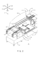
- Fig. 2 is a perspective view illustrating the electronic component mounting machine of the production sequence optimizing system according to this embodiment.
- a housing 36 is transparently shown.
- the electronic component mounting machine 1a includes a base 2, a module 3, a plurality of component supply devices 4, and a device pallet 5.
- the base 2 is arranged on the floor F of a factory.
- the module 3 is detachably provided on the upper surface of the base 2.
- the module 3 includes a board transfer unit 30, an XY robot 31, a mounting head 32, a nozzle stocker 33, and the housing 36.
- the housing 36 forms the outer shell of the module 3.
- the board transfer unit 30 includes a pair of front and rear wall portions 300. Conveyer belts 301 are provided on the rear surface of the front wall portion 300 and the front surface of the rear wall portion 300. A board 90 is provided on the pair of front and rear conveyer belts 301.
- the XY robot 31 includes a Y-direction slider 310, an X-direction slider 311, a pair of left and right Y-direction guide rails 312, and a pair of upper and lower X-direction guide rails 313.
- the pair of left and right Y-direction guide rails 312 are provided on the lower surface of the upper wall of the housing 36.
- the Y-direction slider 310 is attached to the pair of left and right Y-direction guide rails 312 so as to be slidable in the front-rear direction.
- the pair of upper and lower X-direction guide rails 313 are provided on the front surface of the Y-direction slider 310.
- the X-direction slider 311 is attached to the pair of upper and lower X-direction guide rails 313 so as to be slidable in the left-right direction.
- the mounting head 32 is attached to the X-direction slider 311. Therefore, the mounting head 32 can be moved in the front-rear direction and the left-right direction by the XY robot 31.
- a nozzle 320 is attached on the lower side of the mounting head 32 so as to be replaceable.
- the nozzle stocker 33 is detachably provided on the front side of the board transfer unit 30.
- a plurality of nozzles 320 are provided in the nozzle stocker 33.
- the mounting head 32 can replace the nozzle 320 used in the nozzle stocker 33.
- Fig. 3 is a perspective view illustrating the device pallet. As shown in Fig. 3 , the device pallet 5 includes a plurality of slots 50.
- the component supply device 4 includes a tape 40, a reel 41, and a feeder 42.
- a plurality of electronic components are arranged on the tape 40 at predetermined intervals in the longitudinal direction. The same type of electronic components are arranged on a single tape 40.
- the tape 40 is wound around the reel 41.
- the reel 41 is detachably accommodated in the feeder 42.
- the leading end of the tape 40 is drawn from the reel 41 to the rear side.
- the electronic component is picked up from the leading end of the tape 40 with the nozzle 320 shown in Fig. 2 .
- the electronic component which is picked up is transferred to the board 90 by the mounting head 32 and the XY robot 31 and is then mounted at a predetermined mounting position.
- the host computer 8 is electrically connected to all of the electronic component mounting machines 1a to 1d through a network N.
- the host computer 8 includes an arithmetic unit 80, a storage unit 81, an input unit 82, and a monitor 83.
- the arithmetic unit 80 is a central processing unit (CPU).
- the storage unit 81 includes a read only memory (ROM) and a random access memory (RAM).
- the input unit 82 is used by the operator to input instructions to each operating machine provided in the production line L or to input data. The state of the host computer 8 or each operating machine provided in the production line L is displayed on the monitor 83.
- a method for replacing the feeders 42 that is, the electronic components in the electronic component mounting machine 1a
- there are two methods that is, a method for individually replacing the feeders 42 and a method for collectively replacing all feeders 42.
- the feeders 42 are individually replaced, the feeders 42 are mounted one by one in the slots 50 of the device pallet 5 attached to the electronic component mounting machine 1a.
- a pallet change unit (PCU) is used.
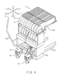
- Fig. 4 is a perspective view illustrating the PCU.
- a PCU 6 includes a unit body 60, four casters 61, and two handles 62.
- a plurality of feeders 42 for each device pallet 5 are mounted to the unit body 60.
- the plurality of feeders 42 for each device pallet 5 are mounted to the electronic component mounting machine 1a.
- the same production line L is used to continuously produce a first type of boards 90 and a second type of boards 90. It is preferable to prepare for the production of the second type of boards 90 while the first type of boards 90 are being produced, in order to reduce downtime caused by a setup operation.
- the reel 41 around which the tape 40 including the electronic components required to produce the second type of boards 90 is wound, can be provided in advance in the feeder 42 which is not used to produce the first type of boards 90, as shown in Fig. 3 .
- the reel 41 around which the tape 40 including the electronic components required to produce the second type of boards 90 is wound, can be provided in advance in the feeder 42 which is not used to produce the first type of boards 90 and the feeders 42 for each device pallet 5 can be mounted to the PCU 6 in advance, as shown in Fig. 4 .
- a method for collectively replacing all nozzles 320 as a method for replacing the nozzles 320 in the electronic component mounting machine 1a.
- the same production line L is used to continuously produce the first type of boards 90 and the second type of boards 90.
- the nozzle 320 which is not used to produce the first type of boards 90 and is used to produce the second type of boards 90 can be inserted in advance into the nozzle stocker 33 which is not used to produce the first type of boards 90.
- the production sequence optimizing method according to this embodiment includes a production program selection step, a priority setting step, a resource counting step, a setup method selection step, a reference optimization step, and a resource allocation step.
- Fig. 5 is a flowchart illustrating the production sequence optimizing method according to this embodiment.
- the arithmetic unit 80 of the host computer 8 shown in Fig. 1 selects a plurality of production programs which are continuously executed using the production line L among a plurality of production programs (corresponding to the types of boards 90) stored in the storage unit 81.
- the arithmetic unit 80 sets priorities for the selected plurality of production programs. That is, the arithmetic unit 80 sets the priorities on the basis of, for example, the number of boards 90 produced or the degree of importance of the board 90.
- the operator inputs the number of all feeders 42 held in stock to the input unit 82 of the host computer 8 shown in Fig. 1 for each type of feeder 42.
- the operator inputs the number of all nozzles 320 held in stock to the input unit 82 for each type of nozzle 320.
- the input number of feeders 42 and the input number of nozzles 320 are stored in the storage unit 81.
- the operator inputs a method for replacing the feeder 42 during setup to the input unit 82. That is, as described above, the methods for replacing the feeder 42 include a method for individually replacing the feeders 42 and a method for collectively replacing all feeders 42. In this step, the operator selects one of the replacement methods during setup.
- the arithmetic unit 80 optimizes the production program with the highest priority which is set in the priority setting step (S2). That is, first, the arithmetic unit 80 allocates the number of feeders 42 for each type of feeder 42 and the number of nozzles 320 for each type of nozzle 320 to the production program with the highest priority such that the cycle time is minimized when the board 90 is produced.
- the arithmetic unit 80 extracts another production program which can share the feeders 42 and the nozzles 320 with the optimized production program from the production programs selected in the production program selection step (S1). Then, the arithmetic unit 80 sets one group (hereinafter, referred to as a reference group) including the optimized production program and the extracted production program.
- the arithmetic unit 80 allocates the number of feeders 42 and the number of nozzles 320 to another production program on the basis of the number of feeders 42 and the number of nozzles 320 allocated to the production program (that is, the reference group) with the highest priority in the reference optimization step (S5).
- the arithmetic unit 80 allocates the number of feeders 42 for each type of feeder 42 and the number of nozzles 320 for each type of nozzle 320 to all the production programs selected in the production program selection step (S1).
- the arithmetic unit 80 allocates the feeders 42 to each group using the following Expression (1) (S11): X ⁇ 0 - X ⁇ 1 + X ⁇ 3 ⁇ X ⁇ 2 (where X0 is the number of all feeders 42 of an arbitrary type, X1 is the number of feeders 42 required for an N-th (N is a natural number) group, X2 is the number of feeders 42 required for an (N+1) -th group, and X3 is the number of feeders 42 shared by the N-th group and the (N+1)-th group).
- Expression (1) (S11): X ⁇ 0 - X ⁇ 1 + X ⁇ 3 ⁇ X ⁇ 2 (where X0 is the number of all feeders 42 of an arbitrary type, X1 is the number of feeders 42 required for an N-th (N is a natural number) group, X2 is the number of feeders 42 required for an (N+1) -th group, and X3
- Fig. 6 is a schematic diagram illustrating a feeder allocation operation when the method for individually replacing the feeders is selected.
- the feeders 42 of type #1 there are 100 feeders 42 held in stock (S3). Therefore, in Expression (1), X0 is 100.
- the number of feeders 42 is set such that Expression (1) is established between group 1 and group 2, between group 2 and group 3, and between group 3 and group 4.
- Expression (1) is established between group 1 and group 2, between group 2 and group 3, and between group 3 and group 4.
- the reels 41 that is, the tapes 40
- the reels 41 for group 2 can be arranged in the 50 feeders 42 used in group 2 in advance outside the production line L.
- 30 feeders 42 can be used to produce group 2. Therefore, it is possible to perform the setup operation in a short amount of time when production is switched from group 1 to group 2. That is, it is possible to reduce downtime.
- the reference group is not limited to the first group 1.
- the arithmetic unit 80 allocates other feeders 42 of type #2 to each of groups 1 to 4, similarly to the feeders 42 of type #1.
- the arithmetic unit 80 allocates the feeders 42 to each group using the following Expression (2) (S7): X ⁇ 1 + X ⁇ 2 ⁇ X ⁇ 0 (where X0 is the number of all feeders 42 of an arbitrary type, X1 is the number of feeders 42 required for an N-th group, and X2 is the number of feeders 42 required for an (N+1) -th group).
- Fig. 7 is a schematic diagram illustrating a feeder allocation operation when the method for collectively replacing all feeders is selected.
- the feeders 42 of type #1 there are 100 feeders 42 held in stock (S3). Therefore, in Expression (2), X0 is 100.
- the number of feeders 42 is set such that Expression (2) is established between group 1 and group 2, between group 2 and group 3, and between group 3 and group 4.
- Expression (2) is established between group 1 and group 2, between group 2 and group 3, and between group 3 and group 4.
- the 50 feeders 42 used in group 2 can be mounted in the PCU 6 in advance outside the production line L. Therefore, it is possible to perform the setup operation in a short amount of time when production is switched from group 1 to group 2. That is, it is possible to reduce downtime.
- the reference group is not limited to the first group 1.
- the arithmetic unit 80 allocates other feeders 42 of type #2 to each of groups 1 to 4, similarly to the feeders 42 of type #1.
- the arithmetic unit 80 allocates the nozzles 320 to each group using the following Expression (3) (S8): Y ⁇ 1 + Y ⁇ 2 ⁇ Y ⁇ 0 (where Y0 is the number of all nozzles 320 of an arbitrary type, Y1 is the number of nozzles 320 required for an N-th group, and Y2 is the number of nozzles 320 required for an (N+1)-th group).
- Fig. 8 is a schematic diagram illustrating a nozzle allocation operation.
- the number of nozzles 320 held in stock is 50 (S3). Therefore, in Expression (3), Y0 is 50.
- the number of nozzles 320 is set such that Expression (3) is established between group 1 and group 2, between group 2 and group 3, and between group 3 and group 4.
- Expression (3) is established between group 1 and group 2, between group 2 and group 3, and between group 3 and group 4.
- Fig. 8 when group 1 is being produced, 25 nozzles 320 are used for production. However, among the 50 nozzles 320 held in stock, 25 nozzles 320 are not used and remain. Therefore, as shown in Fig. 2 , the 25 nozzles 320 used in group 2 can be inserted into the nozzle stocker 33 in advance outside the production line L. Therefore, it is possible to perform the setup operation in a short amount of time when production is switched from group 1 to group 2. That is, it is possible to reduce downtime.
- the reference group is not limited to the first group 1.
- the arithmetic unit 80 allocates other nozzles 320 of type #2 to each of groups 1 to 4, similarly to the nozzles 320 of type #1.
- the arithmetic unit 80 optimizes all of the production programs to be executed (S9). When the optimization result is appropriate, the process ends (S10).
- the arithmetic unit 80 reduces the number of feeders 42 and the number of nozzles 320 arranged in the group having the production program with the highest priority (S12) .
- the arithmetic unit 80 reduces the number of feeders 42 arranged and the number of nozzles 320 arranged. Then, the arithmetic unit 80 performs the reference optimization step (S5) again.
- the production sequence optimizing method and the production sequence optimizing system 9 of this embodiment it is possible to optimize the execution order of a plurality of production programs, considering the number of feeders 42 held in stock and the number of nozzles 320 held in stock, as shown in Fig. 5 . That is, when production is switched from the N-th group to the (N+1)-th group, the feeders 42 and the nozzles 320 are allocated to each group such that the setup operation is performed outside the production line if possible. Therefore, according to the production sequence optimizing method and the production sequence optimizing system 9 of this embodiment, it is possible to reduce downtime caused by the setup operation.
- the feeders 42 and the nozzles 320 can be first allocated to the production program with the highest priority, as shown in Fig. 5 . Then, it is possible to allocate the feeders 42 and the nozzles 320 to each group on the basis of the production program.
- the type of resources is not particularly limited.
- the resources may be trays on which the electronic components are mounted.
- a method for allocating the resources is not particularly limited.
- Fig. 9 is a flowchart illustrating another embodiment of the production sequence optimizing method according to the invention.
- components corresponding to those shown in Fig. 5 are denoted by the same reference numerals.
- the number of feeders 42 and the number of nozzles 320 arranged in the group with the highest priority are reduced (S12).
- the number of production programs in one group may be reduced (S13). That is, it is preferable to maximize the number of production programs included in the same group, in order to improve the efficiency of the setup operation.
- the number of feeders 42 and the number of nozzles 320 required for one group increase. Therefore, when the optimization result is not appropriate, the number of production programs in one group may be reduced and the reference optimization step (S5) may be performed again.
Landscapes
- Engineering & Computer Science (AREA)
- Manufacturing & Machinery (AREA)
- Physics & Mathematics (AREA)
- General Engineering & Computer Science (AREA)
- General Physics & Mathematics (AREA)
- Software Systems (AREA)
- Theoretical Computer Science (AREA)
- Operations Research (AREA)
- Microelectronics & Electronic Packaging (AREA)
- Quality & Reliability (AREA)
- Automation & Control Theory (AREA)
- Supply And Installment Of Electrical Components (AREA)
- General Factory Administration (AREA)
- Management, Administration, Business Operations System, And Electronic Commerce (AREA)
Applications Claiming Priority (1)
| Application Number | Priority Date | Filing Date | Title |
|---|---|---|---|
| PCT/JP2012/073353 WO2014041640A1 (fr) | 2012-09-12 | 2012-09-12 | Procédé d'optimisation de séquence de production et système d'optimisation de séquence de production |
Publications (3)
| Publication Number | Publication Date |
|---|---|
| EP2897009A1 true EP2897009A1 (fr) | 2015-07-22 |
| EP2897009A4 EP2897009A4 (fr) | 2015-08-26 |
| EP2897009B1 EP2897009B1 (fr) | 2023-03-01 |
Family
ID=50277795
Family Applications (1)
| Application Number | Title | Priority Date | Filing Date |
|---|---|---|---|
| EP12884735.7A Active EP2897009B1 (fr) | 2012-09-12 | 2012-09-12 | Procédé d'optimisation de séquence de production et système d'optimisation de séquence de production |
Country Status (5)
| Country | Link |
|---|---|
| US (1) | US10139813B2 (fr) |
| EP (1) | EP2897009B1 (fr) |
| JP (1) | JP5955971B2 (fr) |
| CN (1) | CN104620187B (fr) |
| WO (1) | WO2014041640A1 (fr) |
Cited By (1)
| Publication number | Priority date | Publication date | Assignee | Title |
|---|---|---|---|---|
| EP3267782A4 (fr) * | 2015-03-05 | 2018-03-21 | Fuji Machine Mfg. Co., Ltd. | Dispositif de gestion de montage |
Families Citing this family (20)
| Publication number | Priority date | Publication date | Assignee | Title |
|---|---|---|---|---|
| JP6732038B2 (ja) * | 2016-11-09 | 2020-07-29 | 株式会社Fuji | 部品実装ラインの生産管理システム及び生産管理方法 |
| EP3544400B1 (fr) * | 2016-11-17 | 2021-04-21 | Fuji Corporation | Dispositif de prise en charge de réglages |
| CN106774196B (zh) * | 2016-11-30 | 2019-02-15 | 京东方科技集团股份有限公司 | 在制品管控方法和在制品管控系统 |
| US10925201B2 (en) * | 2017-02-09 | 2021-02-16 | Fuji Corporation | Optimization device for production line |
| JP6965603B2 (ja) * | 2017-07-06 | 2021-11-10 | 富士通株式会社 | 設計支援装置、設計支援方法および設計支援プログラム |
| EP3474650B1 (fr) | 2017-10-19 | 2020-12-09 | Sick Ag | Procédé d'élaboration d'un ensemble d'adaptation pour une machine de montage de composants |
| CN112292919B (zh) * | 2018-05-28 | 2021-10-08 | 株式会社富士 | 单元更换装置 |
| US11765876B2 (en) * | 2018-06-12 | 2023-09-19 | Fuji Corporation | Exchange device |
| US11723184B2 (en) * | 2018-06-26 | 2023-08-08 | Fuji Corporation | Component supply unit arrangement determination method and component mounting system |
| WO2020039495A1 (fr) * | 2018-08-21 | 2020-02-27 | 株式会社Fuji | Système de montage de composants |
| EP3843516B1 (fr) * | 2018-08-23 | 2023-03-22 | Fuji Corporation | Dispositif de gestion de travail mobile, système de montage et procédé de gestion de travail mobile |
| US12063744B2 (en) * | 2018-08-23 | 2024-08-13 | Fuji Corporation | Moving work management device, moving work device, mounting system, and management method |
| CN112567901B (zh) * | 2018-08-23 | 2022-07-22 | 株式会社富士 | 移动作业管理装置、移动型作业装置、安装系统及移动作业管理方法 |
| US11943873B2 (en) * | 2019-02-06 | 2024-03-26 | Fuji Corporation | Management device, movable work device, mounting system, and management method |
| EP3927133B1 (fr) * | 2019-02-15 | 2024-01-03 | Fuji Corporation | Système de montage de composants et dispositif de création de données |
| WO2020170305A1 (fr) * | 2019-02-18 | 2020-08-27 | 株式会社Fuji | Dispositif de réglage de tâches de changement de configuration |
| JPWO2021010033A1 (fr) * | 2019-07-18 | 2021-01-21 | ||
| CN111479404B (zh) * | 2020-05-09 | 2021-06-01 | 宁波智能装备研究院有限公司 | 一种基于混合遗传算法的led贴片机拾贴路径优化方法 |
| JP7474862B2 (ja) * | 2020-11-06 | 2024-04-25 | 株式会社Fuji | 部品実装システム |
| CN114879611B (zh) * | 2022-03-23 | 2025-12-23 | 浙江大豪科技有限公司 | 设备控制方法、装置及设备 |
Family Cites Families (11)
| Publication number | Priority date | Publication date | Assignee | Title |
|---|---|---|---|---|
| US5155679A (en) * | 1989-12-18 | 1992-10-13 | Hewlett-Packard Company | Set-up optimization for flexible manufacturing systems |
| JP2966082B2 (ja) * | 1990-11-06 | 1999-10-25 | 株式会社日立製作所 | 実装順序決定方法及びその実装方法 |
| JPH05257918A (ja) * | 1992-03-11 | 1993-10-08 | Nec Corp | 部品割付決定装置 |
| JP3447008B2 (ja) | 2001-05-17 | 2003-09-16 | 松下電器産業株式会社 | 部品実装順序最適化方法、その装置及び部品実装機 |
| JP2003101294A (ja) * | 2001-09-20 | 2003-04-04 | Fuji Mach Mfg Co Ltd | 電気部品供給方法および電気部品装着システム |
| JP3589658B2 (ja) * | 2001-09-28 | 2004-11-17 | 松下電器産業株式会社 | 最適化装置、装着装置及び電子部品装着システム |
| JP4162930B2 (ja) * | 2002-06-25 | 2008-10-08 | 富士機械製造株式会社 | 電子部品実装装置における基板搬送装置 |
| US6829514B2 (en) * | 2003-01-17 | 2004-12-07 | Motorola, Inc. | Balancing workloads in an electronics assembly factory |
| JP2004287540A (ja) * | 2003-03-19 | 2004-10-14 | Kawasaki Heavy Ind Ltd | 設備のグルーピング方法およびグルーピング装置 |
| JP4545115B2 (ja) * | 2005-07-05 | 2010-09-15 | パナソニック株式会社 | 生産条件決定方法、生産条件決定装置、部品実装機およびプログラム |
| JP4943299B2 (ja) * | 2007-02-09 | 2012-05-30 | Juki株式会社 | 部品実装装置のフィーダ配置方法 |
-
2012
- 2012-09-12 WO PCT/JP2012/073353 patent/WO2014041640A1/fr not_active Ceased
- 2012-09-12 JP JP2014535287A patent/JP5955971B2/ja active Active
- 2012-09-12 US US14/427,410 patent/US10139813B2/en active Active
- 2012-09-12 CN CN201280075745.3A patent/CN104620187B/zh active Active
- 2012-09-12 EP EP12884735.7A patent/EP2897009B1/fr active Active
Cited By (2)
| Publication number | Priority date | Publication date | Assignee | Title |
|---|---|---|---|---|
| EP3267782A4 (fr) * | 2015-03-05 | 2018-03-21 | Fuji Machine Mfg. Co., Ltd. | Dispositif de gestion de montage |
| US11006558B2 (en) | 2015-03-05 | 2021-05-11 | Fuji Corporation | Mounting management device |
Also Published As
| Publication number | Publication date |
|---|---|
| JP5955971B2 (ja) | 2016-07-20 |
| EP2897009B1 (fr) | 2023-03-01 |
| WO2014041640A1 (fr) | 2014-03-20 |
| EP2897009A4 (fr) | 2015-08-26 |
| US20150248314A1 (en) | 2015-09-03 |
| US10139813B2 (en) | 2018-11-27 |
| CN104620187B (zh) | 2017-08-29 |
| CN104620187A (zh) | 2015-05-13 |
| JPWO2014041640A1 (ja) | 2016-08-12 |
Similar Documents
| Publication | Publication Date | Title |
|---|---|---|
| EP2897009A1 (fr) | Procédé d'optimisation de séquence de production et système d'optimisation de séquence de production | |
| EP2894528B1 (fr) | Procédé de gestion de chaînes de production et système de gestion de chaînes de production | |
| US10824782B2 (en) | Information processing device, recording medium recording production plan generation program, and production plan generation method | |
| JP5480776B2 (ja) | 実装モード決定方法及び部品実装システム | |
| EP3038442B1 (fr) | Dispositif d'optimisation de production pour ligne de montage de composants | |
| US7603193B2 (en) | Method for optimization of an order for component mounting and apparatus for optimization of an order for component mounting | |
| JPWO2015019412A1 (ja) | 準備作業支援システム | |
| JP6267202B2 (ja) | フィーダ自動配膳制御装置および制御方法 | |
| US11259450B2 (en) | Method of determining disposition of component supply unit and apparatus for determining disposition of component supply unit | |
| JP2014197594A (ja) | 電子部品管理システム | |
| US12089341B2 (en) | Component mounting system and data creation device | |
| EP3383159B1 (fr) | Dispositif d'optimisation de ligne de montage de composants et procédé d'optimisation de ligne de montage de composants | |
| EP3826445B1 (fr) | Système de montage de composant | |
| EP3220730B1 (fr) | Dispositif de commande pour dispositif de fixation de composant électronique | |
| JP6194365B2 (ja) | 実装装置及び実装管理装置 | |
| US6591486B1 (en) | Manufacturing and carrier system with feeder/Programming/buffer system | |
| JP2009231808A (ja) | 実装条件決定方法 | |
| JPWO2020003378A1 (ja) | 部品供給ユニットの配置決定方法および部品実装システム | |
| JP4847984B2 (ja) | 実装条件決定方法 | |
| JP2009224766A (ja) | 実装条件決定方法、実装条件決定装置、部品実装方法、部品実装機及びプログラム | |
| JP4869383B2 (ja) | 実装条件決定方法 | |
| EP3557967B1 (fr) | Engin de chantier | |
| JP2025108202A (ja) | 生産支援装置および生産支援方法 | |
| WO2009144908A1 (fr) | Procédé de détermination de conditions de montage, dispositif de détermination de conditions de montage, procédé de montage de composant et machine de montage de composant |
Legal Events
| Date | Code | Title | Description |
|---|---|---|---|
| PUAI | Public reference made under article 153(3) epc to a published international application that has entered the european phase |
Free format text: ORIGINAL CODE: 0009012 |
|
| 17P | Request for examination filed |
Effective date: 20150312 |
|
| AK | Designated contracting states |
Kind code of ref document: A1 Designated state(s): AL AT BE BG CH CY CZ DE DK EE ES FI FR GB GR HR HU IE IS IT LI LT LU LV MC MK MT NL NO PL PT RO RS SE SI SK SM TR |
|
| AX | Request for extension of the european patent |
Extension state: BA ME |
|
| RA4 | Supplementary search report drawn up and despatched (corrected) |
Effective date: 20150724 |
|
| RIC1 | Information provided on ipc code assigned before grant |
Ipc: G05B 19/418 20060101AFI20150720BHEP Ipc: H05K 13/08 20060101ALI20150720BHEP |
|
| DAX | Request for extension of the european patent (deleted) | ||
| RAP1 | Party data changed (applicant data changed or rights of an application transferred) |
Owner name: FUJI CORPORATION |
|
| RIN1 | Information on inventor provided before grant (corrected) |
Inventor name: MORITA YUKITOSHI |
|
| STAA | Information on the status of an ep patent application or granted ep patent |
Free format text: STATUS: EXAMINATION IS IN PROGRESS |
|
| 17Q | First examination report despatched |
Effective date: 20190717 |
|
| GRAP | Despatch of communication of intention to grant a patent |
Free format text: ORIGINAL CODE: EPIDOSNIGR1 |
|
| STAA | Information on the status of an ep patent application or granted ep patent |
Free format text: STATUS: GRANT OF PATENT IS INTENDED |
|
| INTG | Intention to grant announced |
Effective date: 20220916 |
|
| GRAS | Grant fee paid |
Free format text: ORIGINAL CODE: EPIDOSNIGR3 |
|
| GRAA | (expected) grant |
Free format text: ORIGINAL CODE: 0009210 |
|
| STAA | Information on the status of an ep patent application or granted ep patent |
Free format text: STATUS: THE PATENT HAS BEEN GRANTED |
|
| AK | Designated contracting states |
Kind code of ref document: B1 Designated state(s): AL AT BE BG CH CY CZ DE DK EE ES FI FR GB GR HR HU IE IS IT LI LT LU LV MC MK MT NL NO PL PT RO RS SE SI SK SM TR |
|
| REG | Reference to a national code |
Ref country code: GB Ref legal event code: FG4D |
|
| REG | Reference to a national code |
Ref country code: CH Ref legal event code: EP Ref country code: AT Ref legal event code: REF Ref document number: 1551416 Country of ref document: AT Kind code of ref document: T Effective date: 20230315 |
|
| REG | Reference to a national code |
Ref country code: DE Ref legal event code: R096 Ref document number: 602012079334 Country of ref document: DE |
|
| REG | Reference to a national code |
Ref country code: IE Ref legal event code: FG4D |
|
| P01 | Opt-out of the competence of the unified patent court (upc) registered |
Effective date: 20230328 |
|
| REG | Reference to a national code |
Ref country code: LT Ref legal event code: MG9D |
|
| REG | Reference to a national code |
Ref country code: NL Ref legal event code: MP Effective date: 20230301 |
|
| PG25 | Lapsed in a contracting state [announced via postgrant information from national office to epo] |
Ref country code: RS Free format text: LAPSE BECAUSE OF FAILURE TO SUBMIT A TRANSLATION OF THE DESCRIPTION OR TO PAY THE FEE WITHIN THE PRESCRIBED TIME-LIMIT Effective date: 20230301 Ref country code: NO Free format text: LAPSE BECAUSE OF FAILURE TO SUBMIT A TRANSLATION OF THE DESCRIPTION OR TO PAY THE FEE WITHIN THE PRESCRIBED TIME-LIMIT Effective date: 20230601 Ref country code: LV Free format text: LAPSE BECAUSE OF FAILURE TO SUBMIT A TRANSLATION OF THE DESCRIPTION OR TO PAY THE FEE WITHIN THE PRESCRIBED TIME-LIMIT Effective date: 20230301 Ref country code: LT Free format text: LAPSE BECAUSE OF FAILURE TO SUBMIT A TRANSLATION OF THE DESCRIPTION OR TO PAY THE FEE WITHIN THE PRESCRIBED TIME-LIMIT Effective date: 20230301 Ref country code: HR Free format text: LAPSE BECAUSE OF FAILURE TO SUBMIT A TRANSLATION OF THE DESCRIPTION OR TO PAY THE FEE WITHIN THE PRESCRIBED TIME-LIMIT Effective date: 20230301 Ref country code: ES Free format text: LAPSE BECAUSE OF FAILURE TO SUBMIT A TRANSLATION OF THE DESCRIPTION OR TO PAY THE FEE WITHIN THE PRESCRIBED TIME-LIMIT Effective date: 20230301 |
|
| REG | Reference to a national code |
Ref country code: AT Ref legal event code: MK05 Ref document number: 1551416 Country of ref document: AT Kind code of ref document: T Effective date: 20230301 |
|
| PG25 | Lapsed in a contracting state [announced via postgrant information from national office to epo] |
Ref country code: SE Free format text: LAPSE BECAUSE OF FAILURE TO SUBMIT A TRANSLATION OF THE DESCRIPTION OR TO PAY THE FEE WITHIN THE PRESCRIBED TIME-LIMIT Effective date: 20230301 Ref country code: PL Free format text: LAPSE BECAUSE OF FAILURE TO SUBMIT A TRANSLATION OF THE DESCRIPTION OR TO PAY THE FEE WITHIN THE PRESCRIBED TIME-LIMIT Effective date: 20230301 Ref country code: NL Free format text: LAPSE BECAUSE OF FAILURE TO SUBMIT A TRANSLATION OF THE DESCRIPTION OR TO PAY THE FEE WITHIN THE PRESCRIBED TIME-LIMIT Effective date: 20230301 Ref country code: GR Free format text: LAPSE BECAUSE OF FAILURE TO SUBMIT A TRANSLATION OF THE DESCRIPTION OR TO PAY THE FEE WITHIN THE PRESCRIBED TIME-LIMIT Effective date: 20230602 Ref country code: FI Free format text: LAPSE BECAUSE OF FAILURE TO SUBMIT A TRANSLATION OF THE DESCRIPTION OR TO PAY THE FEE WITHIN THE PRESCRIBED TIME-LIMIT Effective date: 20230301 |
|
| PG25 | Lapsed in a contracting state [announced via postgrant information from national office to epo] |
Ref country code: SM Free format text: LAPSE BECAUSE OF FAILURE TO SUBMIT A TRANSLATION OF THE DESCRIPTION OR TO PAY THE FEE WITHIN THE PRESCRIBED TIME-LIMIT Effective date: 20230301 Ref country code: RO Free format text: LAPSE BECAUSE OF FAILURE TO SUBMIT A TRANSLATION OF THE DESCRIPTION OR TO PAY THE FEE WITHIN THE PRESCRIBED TIME-LIMIT Effective date: 20230301 Ref country code: PT Free format text: LAPSE BECAUSE OF FAILURE TO SUBMIT A TRANSLATION OF THE DESCRIPTION OR TO PAY THE FEE WITHIN THE PRESCRIBED TIME-LIMIT Effective date: 20230703 Ref country code: EE Free format text: LAPSE BECAUSE OF FAILURE TO SUBMIT A TRANSLATION OF THE DESCRIPTION OR TO PAY THE FEE WITHIN THE PRESCRIBED TIME-LIMIT Effective date: 20230301 Ref country code: CZ Free format text: LAPSE BECAUSE OF FAILURE TO SUBMIT A TRANSLATION OF THE DESCRIPTION OR TO PAY THE FEE WITHIN THE PRESCRIBED TIME-LIMIT Effective date: 20230301 Ref country code: AT Free format text: LAPSE BECAUSE OF FAILURE TO SUBMIT A TRANSLATION OF THE DESCRIPTION OR TO PAY THE FEE WITHIN THE PRESCRIBED TIME-LIMIT Effective date: 20230301 |
|
| PG25 | Lapsed in a contracting state [announced via postgrant information from national office to epo] |
Ref country code: SK Free format text: LAPSE BECAUSE OF FAILURE TO SUBMIT A TRANSLATION OF THE DESCRIPTION OR TO PAY THE FEE WITHIN THE PRESCRIBED TIME-LIMIT Effective date: 20230301 Ref country code: IS Free format text: LAPSE BECAUSE OF FAILURE TO SUBMIT A TRANSLATION OF THE DESCRIPTION OR TO PAY THE FEE WITHIN THE PRESCRIBED TIME-LIMIT Effective date: 20230701 |
|
| REG | Reference to a national code |
Ref country code: DE Ref legal event code: R097 Ref document number: 602012079334 Country of ref document: DE |
|
| PLBE | No opposition filed within time limit |
Free format text: ORIGINAL CODE: 0009261 |
|
| STAA | Information on the status of an ep patent application or granted ep patent |
Free format text: STATUS: NO OPPOSITION FILED WITHIN TIME LIMIT |
|
| PG25 | Lapsed in a contracting state [announced via postgrant information from national office to epo] |
Ref country code: SI Free format text: LAPSE BECAUSE OF FAILURE TO SUBMIT A TRANSLATION OF THE DESCRIPTION OR TO PAY THE FEE WITHIN THE PRESCRIBED TIME-LIMIT Effective date: 20230301 Ref country code: DK Free format text: LAPSE BECAUSE OF FAILURE TO SUBMIT A TRANSLATION OF THE DESCRIPTION OR TO PAY THE FEE WITHIN THE PRESCRIBED TIME-LIMIT Effective date: 20230301 |
|
| 26N | No opposition filed |
Effective date: 20231204 |
|
| REG | Reference to a national code |
Ref country code: CH Ref legal event code: PL |
|
| PG25 | Lapsed in a contracting state [announced via postgrant information from national office to epo] |
Ref country code: LU Free format text: LAPSE BECAUSE OF NON-PAYMENT OF DUE FEES Effective date: 20230912 |
|
| REG | Reference to a national code |
Ref country code: BE Ref legal event code: MM Effective date: 20230930 |
|
| GBPC | Gb: european patent ceased through non-payment of renewal fee |
Effective date: 20230912 |
|
| PG25 | Lapsed in a contracting state [announced via postgrant information from national office to epo] |
Ref country code: LU Free format text: LAPSE BECAUSE OF NON-PAYMENT OF DUE FEES Effective date: 20230912 Ref country code: IT Free format text: LAPSE BECAUSE OF FAILURE TO SUBMIT A TRANSLATION OF THE DESCRIPTION OR TO PAY THE FEE WITHIN THE PRESCRIBED TIME-LIMIT Effective date: 20230301 Ref country code: MC Free format text: LAPSE BECAUSE OF FAILURE TO SUBMIT A TRANSLATION OF THE DESCRIPTION OR TO PAY THE FEE WITHIN THE PRESCRIBED TIME-LIMIT Effective date: 20230301 |
|
| REG | Reference to a national code |
Ref country code: IE Ref legal event code: MM4A |
|
| PG25 | Lapsed in a contracting state [announced via postgrant information from national office to epo] |
Ref country code: IE Free format text: LAPSE BECAUSE OF NON-PAYMENT OF DUE FEES Effective date: 20230912 |
|
| PG25 | Lapsed in a contracting state [announced via postgrant information from national office to epo] |
Ref country code: GB Free format text: LAPSE BECAUSE OF NON-PAYMENT OF DUE FEES Effective date: 20230912 |
|
| PG25 | Lapsed in a contracting state [announced via postgrant information from national office to epo] |
Ref country code: CH Free format text: LAPSE BECAUSE OF NON-PAYMENT OF DUE FEES Effective date: 20230930 |
|
| PG25 | Lapsed in a contracting state [announced via postgrant information from national office to epo] |
Ref country code: IE Free format text: LAPSE BECAUSE OF NON-PAYMENT OF DUE FEES Effective date: 20230912 Ref country code: GB Free format text: LAPSE BECAUSE OF NON-PAYMENT OF DUE FEES Effective date: 20230912 Ref country code: FR Free format text: LAPSE BECAUSE OF NON-PAYMENT OF DUE FEES Effective date: 20230930 Ref country code: CH Free format text: LAPSE BECAUSE OF NON-PAYMENT OF DUE FEES Effective date: 20230930 |
|
| PG25 | Lapsed in a contracting state [announced via postgrant information from national office to epo] |
Ref country code: BE Free format text: LAPSE BECAUSE OF NON-PAYMENT OF DUE FEES Effective date: 20230930 |
|
| PG25 | Lapsed in a contracting state [announced via postgrant information from national office to epo] |
Ref country code: BG Free format text: LAPSE BECAUSE OF FAILURE TO SUBMIT A TRANSLATION OF THE DESCRIPTION OR TO PAY THE FEE WITHIN THE PRESCRIBED TIME-LIMIT Effective date: 20230301 |
|
| PG25 | Lapsed in a contracting state [announced via postgrant information from national office to epo] |
Ref country code: BG Free format text: LAPSE BECAUSE OF FAILURE TO SUBMIT A TRANSLATION OF THE DESCRIPTION OR TO PAY THE FEE WITHIN THE PRESCRIBED TIME-LIMIT Effective date: 20230301 |
|
| PG25 | Lapsed in a contracting state [announced via postgrant information from national office to epo] |
Ref country code: CY Free format text: LAPSE BECAUSE OF FAILURE TO SUBMIT A TRANSLATION OF THE DESCRIPTION OR TO PAY THE FEE WITHIN THE PRESCRIBED TIME-LIMIT; INVALID AB INITIO Effective date: 20120912 |
|
| PG25 | Lapsed in a contracting state [announced via postgrant information from national office to epo] |
Ref country code: HU Free format text: LAPSE BECAUSE OF FAILURE TO SUBMIT A TRANSLATION OF THE DESCRIPTION OR TO PAY THE FEE WITHIN THE PRESCRIBED TIME-LIMIT; INVALID AB INITIO Effective date: 20120912 |
|
| PGFP | Annual fee paid to national office [announced via postgrant information from national office to epo] |
Ref country code: DE Payment date: 20250730 Year of fee payment: 14 |
|
| PG25 | Lapsed in a contracting state [announced via postgrant information from national office to epo] |
Ref country code: TR Free format text: LAPSE BECAUSE OF FAILURE TO SUBMIT A TRANSLATION OF THE DESCRIPTION OR TO PAY THE FEE WITHIN THE PRESCRIBED TIME-LIMIT Effective date: 20230301 |