EP2897128A2 - Ausziehbare Festplattenschublade - Google Patents
Ausziehbare Festplattenschublade Download PDFInfo
- Publication number
- EP2897128A2 EP2897128A2 EP14200695.6A EP14200695A EP2897128A2 EP 2897128 A2 EP2897128 A2 EP 2897128A2 EP 14200695 A EP14200695 A EP 14200695A EP 2897128 A2 EP2897128 A2 EP 2897128A2
- Authority
- EP
- European Patent Office
- Prior art keywords
- hard drive
- drive carrier
- open position
- chassis
- front side
- Prior art date
- Legal status (The legal status is an assumption and is not a legal conclusion. Google has not performed a legal analysis and makes no representation as to the accuracy of the status listed.)
- Granted
Links
Images



Classifications
-
- G—PHYSICS
- G11—INFORMATION STORAGE
- G11B—INFORMATION STORAGE BASED ON RELATIVE MOVEMENT BETWEEN RECORD CARRIER AND TRANSDUCER
- G11B33/00—Constructional parts, details or accessories not provided for in the other groups of this subclass
- G11B33/12—Disposition of constructional parts in the apparatus, e.g. of power supply, of modules
- G11B33/125—Disposition of constructional parts in the apparatus, e.g. of power supply, of modules the apparatus comprising a plurality of recording/reproducing devices, e.g. modular arrangements, arrays of disc drives
- G11B33/127—Mounting arrangements of constructional parts onto a chassis
- G11B33/128—Mounting arrangements of constructional parts onto a chassis of the plurality of recording/reproducing devices, e.g. disk drives, onto a chassis
-
- H—ELECTRICITY
- H05—ELECTRIC TECHNIQUES NOT OTHERWISE PROVIDED FOR
- H05K—PRINTED CIRCUITS; CASINGS OR CONSTRUCTIONAL DETAILS OF ELECTRIC APPARATUS; MANUFACTURE OF ASSEMBLAGES OF ELECTRICAL COMPONENTS
- H05K5/00—Casings, cabinets or drawers for electric apparatus
- H05K5/02—Details
- H05K5/0217—Mechanical details of casings
-
- H—ELECTRICITY
- H05—ELECTRIC TECHNIQUES NOT OTHERWISE PROVIDED FOR
- H05K—PRINTED CIRCUITS; CASINGS OR CONSTRUCTIONAL DETAILS OF ELECTRIC APPARATUS; MANUFACTURE OF ASSEMBLAGES OF ELECTRICAL COMPONENTS
- H05K5/00—Casings, cabinets or drawers for electric apparatus
- H05K5/02—Details
- H05K5/03—Covers
-
- H—ELECTRICITY
- H05—ELECTRIC TECHNIQUES NOT OTHERWISE PROVIDED FOR
- H05K—PRINTED CIRCUITS; CASINGS OR CONSTRUCTIONAL DETAILS OF ELECTRIC APPARATUS; MANUFACTURE OF ASSEMBLAGES OF ELECTRICAL COMPONENTS
- H05K7/00—Constructional details common to different types of electric apparatus
- H05K7/14—Mounting supporting structure in casing or on frame or rack
-
- H—ELECTRICITY
- H05—ELECTRIC TECHNIQUES NOT OTHERWISE PROVIDED FOR
- H05K—PRINTED CIRCUITS; CASINGS OR CONSTRUCTIONAL DETAILS OF ELECTRIC APPARATUS; MANUFACTURE OF ASSEMBLAGES OF ELECTRICAL COMPONENTS
- H05K7/00—Constructional details common to different types of electric apparatus
- H05K7/14—Mounting supporting structure in casing or on frame or rack
- H05K7/1485—Servers; Data center rooms, e.g. 19-inch computer racks
- H05K7/1488—Cabinets therefor, e.g. chassis or racks or mechanical interfaces between blades and support structures
-
- Y—GENERAL TAGGING OF NEW TECHNOLOGICAL DEVELOPMENTS; GENERAL TAGGING OF CROSS-SECTIONAL TECHNOLOGIES SPANNING OVER SEVERAL SECTIONS OF THE IPC; TECHNICAL SUBJECTS COVERED BY FORMER USPC CROSS-REFERENCE ART COLLECTIONS [XRACs] AND DIGESTS
- Y10—TECHNICAL SUBJECTS COVERED BY FORMER USPC
- Y10T—TECHNICAL SUBJECTS COVERED BY FORMER US CLASSIFICATION
- Y10T29/00—Metal working
- Y10T29/49—Method of mechanical manufacture
- Y10T29/49826—Assembling or joining
Definitions
- the disclosure generally relates to accessing hard drives in a server chassis.
- Hard drives are typically housed in a server chassis and are used for storing information in a server.
- the hard drives can be housed at the front of the server chassis for access to the hard drives for the purpose of replacement or maintenance. At times, it may be desirable to maximize the storage capacity of the server by housing many hard drives inside the chassis.
- the server chassis due to space limitations of the server chassis, only a limited amount of hard drives can be housed in the server at once, and, of those hard drives, only a limited number of hard drives can be easily accessible from the front for the purpose of replacement or maintenance.
- an apparatus can be configured with at least one extendable hard drive drawer for replacement and maintenance of at least one hard drive.
- the apparatus comprises a chassis comprising a front side and a rear side, and a first hard drive carrier and a second hard drive carrier housed within the chassis.
- the first hard drive carrier can be housed at the front side of the chassis, and the second hard drive carrier can be located behind the first hard drive carrier.
- the first hard drive carrier and the second hard drive carrier can each be adapted to house at least one hard drive.
- the first hard drive carrier is slidably coupled to the chassis.
- the first hard drive carrier can be adapted to slide from a closed position to a first open position, and from the first open position to a second open position, such that the second hard drive carrier can be accessed in the second open position.
- Particular implementations provide at least the following advantages: front side access to multiple rows of hard drives for the purpose of replacement and maintenance, and maximum storage and organization of hard drives within a server chassis.
- Coupled is defined as connected, whether directly or indirectly through intervening members, and is not necessarily limited to physical connections.
- the connection can be such that the objects are permanently connected or releasably connected.
- substantially is defined to be essentially conforming to the particular dimension, shape or other word that substantially modifies, such that the member need not be exact. For example, substantially cylindrical means that the object resembles a cylinder, but can have one or more deviations from a true cylinder.
- comprising when utilized, means “including, but not necessarily limited to”; it specifically indicates open-ended inclusion or membership in the so-described combination, group, series and the like.
- a first hard drive drawer and a second hard drive drawer are housed within a server chassis at a first closed position.
- the first hard drive drawer can be located at the front of the server chassis, and the second hard drive drawer can be located behind the first hard drive drawer.
- Both the first hard drive drawer and the second hard drive drawer can be adapted to house at least one hard drive, and can be slidably coupled to the server chassis.
- In the first closed position only the first hard drive drawer is accessible from the front of the server chassis.
- the first hard drive drawer can be pulled out from the server chassis to a first open position, such that the first hard drive drawer extends beyond the front of the server.
- the second hard drive drawer becomes accessible from the front of the server for the purpose of hard drive replacement or maintenance.
- the first and second hard drive drawers can be pulled out from the second open position to a third open position.
- at least one fan located behind the second hard drive drawer can be accessed from the front of the server for the purpose of replacement or maintenance.
- the first hard drive drawer is pushed back towards the second hard drive drawer into a second closed position, such that at least the first hard drive drawer abuts the second hard drive drawer and extends beyond the front of the server. Then, both the first and second hard drive drawers are pushed back into the server chassis from the second closed position to the first closed position.
- FIG. 1 illustrates an example extendable hard drive drawer apparatus 100 in a first closed position for accessing tray unit 140 comprising first hard drive drawer 160 and second hard drive drawer 150.
- first hard drive drawer 160 can be spaced apart from second hard drive drawer 150 by at most a distance d2. The closer first hard drive drawer 160 and second hard drive drawer 150 are to each other, the less space they take up in apparatus 100.
- distance d2 can be any numerical amount less than a width of each hard drive drawer 150 and 160 (e.g., 0.5inch, 1cm, etc.).
- first hard drive drawer 160 and second hard drive drawer 150 are not spaced apart.
- first hard drive drawer 160 can be adapted to house at least one hard drive
- second hard drive drawer 150 can be adapted to house at least one hard drive.
- first hard drive drawer 160 can be adapted to house first hard drive group 180
- second hard drive drawer 150 can be adapted to house second hard drive group 170.
- First hard drive group 180 and second hard drive group 170 can comprise a plurality of hard drives (e.g., HDD, SSD, SCSI, SATA, PATA, internal, external, etc.).
- the plurality of hard drives can be grouped above one another and side-by-side according to means known in the art, including, but not limited to, slots, shelves, dividers, rows, columns, etc.
- the plurality of hard drives can be arranged in multiple rows and columns within first and second hard drive groups 180 and 170.
- the plurality of hard drives can be adapted to be removable and hot-swappable according to means known in the art, including, but not limited to, clips, snap fit, friction fit, hard drive caddy, etc.
- apparatus 100 can comprise chassis 101 (e.g., server chassis) for housing first hard drive drawer 160 and second hard drive drawer 150.
- chassis 101 can be any server chassis known in the art (e.g., 1U, 2U, etc.).
- Chassis 101 can be made of any combination of materials, such as, metal, plastic, alloys, etc.
- Chassis 101 can comprise front side 102 and rear side 104.
- first hard drive drawer 160 can be housed in front side 102.
- chassis 101 can house control board 130 (e.g., motherboard).
- control board 130 can be housed at rear side 104.
- Control board 130 can be coupled to tray unit 140 according to cabling means known in the art, including, but not limited to, cable arm, cabling along sides of the chassis, storing cables underneath the drawers, etc.
- chassis 101 can comprise top rail 120 and bottom rail 130.
- top rail 120 can comprise a top grooved section of opposed sides 106 of chassis 101.
- Bottom rail 130 can comprise a bottom grooved second of opposed sides 106 of chassis 101.
- the top and bottom grooved sections can be machined into opposed sides 106 of chassis 101 according to means known in the art for drawers, including, but not limited to, molding, cutting, folding, etc.
- top rail 120 and bottom rail 130 can be machined or otherwise coupled (e.g., using nails or screws) to opposed sides 106 (e.g., according to means commonly known in the art for drawers) such that each rail takes up half the width of each opposed side 106.
- Top rail 120 and bottom rail 130 can be uniform in width, and can run the entire length of opposed sides 106.
- Top rail 120 and bottom rail 130 can be made of the same material as chassis 101 (e.g., metal, plastic, alloys, etc.).
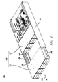
- FIG. 2 illustrates apparatus 100 in a first open position.
- First hard drive drawer 160 is pulled in an outward direction through an outward force 300 from chassis 101.
- second hard drive drawer 150 remains in place within chassis 101.
- first hard drive drawer 160 is coupled to first extendable portion 240 for the purposes of sliding outwardly from chassis 101.
- first extendable portion 240 can be adapted to slide within bottom rail 130 on opposed sides 106.
- first extendable portion 240 and bottom rail 130 can be adapted to be nested within each other such that the rails telescope with respect to one another (e.g., as commonly known in the art for drawers).
- first hard drive drawer 160 can be locked into place a maximum distance apart from second hard drive drawer 150.
- first extendable portion 240 can comprise bars attached to the sides of first hard drive drawer 160.
- the bars can be adapted to slidably fit into bottom rail 130.
- first extendable portion 240 can be adapted to slide out along with first hard drive drawer 160.
- First extendable portion 240 can be made of standard materials in the art for railing, including, but not limited to, plastic, metal, alloys, etc.
- first extendable portion 240 can comprise sliding means known in the art for facilitating movement within bottom rail 130, including, but not limited to, bearings, wheels, sliders, frictionless surfaces, etc.
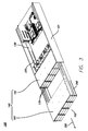
- FIG. 3 illustrates apparatus 100 in a second open position.
- first hard drive drawer 160 and second hard drive drawer 150 remain a fixed distance apart, and both slide out together.
- first hard drive drawer 160 and second hard drive drawer 150 both are pulled in the outward direction through outward force 300 together from the first open position to the second open position.
- outward force 300 is applied only to first hard drive drawer 160, such that second hard drive drawer 150 is a fixed distance (e.g., at least the length of a hard drive) apart from first hard drive drawer 160 as both hard drive drawers 150 and 160 slide outwardly together.
- second hard drive drawer 150 remains a fixed distance behind first hard drive drawer 160 as both hard drive drawers 150 and 160 are simultaneously pulled out.
- first hard drive drawer 160 can be locked into place at the fixed distance apart from second hard drive drawer 150 such that pushing and pulling on first hard drive drawer 160 also causes second hard drive drawer 150 to move at the fixed distance.
- first extendable portion 240 can be adapted to be slidably housed within second extendable portion 220 such that first extendable portion 240 slides independently of second extendable portion 220.
- Second extendable portion 220 can be adapted to be housed within bottom rail 130.
- second extendable portion 220 can be slidably fit into bottom rail 130.
- second extendable portion 220 can be adapted to slide out along with first hard drive drawer 160.
- Second extendable portion 220 can be made of standard materials in the art for railing, including, but not limited to, plastic, metal, alloys, etc.
- second extendable portion 220 can comprise sliding means known in the art for facilitating movement within bottom rail 130, including, but not limited to, bearings, wheels, sliders, frictionless surfaces, etc.
- second hard drive group 170 can be accessed from front side 102 for the purposes of repair, replacement, and maintenance. Because first hard drive drawer 160 and second hard drive drawer 150 are spaced apart at least a distance equal to the length of a hard drive, replacement and maintenance of second hard drive group 170 can be accomplished from front side 102.
- FIG. 4 illustrates apparatus 100 in a third open position.
- First and second hard drive drawers 150 and 160 slide outwardly together from the second open position to the third open position while maintaining the fixed distance between them.
- limiting bar 230 can be used to limit the fixed distance to a maximum distance d1 between first hard drive drawer 160 and second hard drive drawer 150 in the first, second, and third open positions.
- limiting bar 230 can comprise sliding aperture 250 for defining the maximum distance d1 between first hard drive drawer 160 and second hard drive drawer 150.
- the maximum distance d1 is at least a length L of a hard drive that fits into hard drive drawers 150 and 160.
- the distance d1 is big enough to allow a hard drive to be removed from second hard drive drawer 150.
- second hard drive drawer 150 can comprise a fixed point 260 for fixing the maximum distance d1 between first hard drive drawer 160 and second hard drive drawer 150.
- fixed point 260 can be slidably coupled to the sides of second hard drive drawer 150 and sliding aperture 250 of limiting bar 230.
- fixed point 260 slides along sliding aperture 250, to define how close d2 ( FIG. 1 ) and how far apart d1 first hard drive drawer 160 and second hard drive drawer 150 are.
- sliding aperture 250 runs a defined distance along the length of limiting bar 230. The defined distance determines how close d2 ( FIG. 1 ) and how far apart d1 first hard drive drawer 160 can be from second hard drive drawer 150.
- second hard drive drawer 150 can be coupled to top extending portion 210.
- top extending portion 210 can be adapted to slidably fit into top rail 120.
- Top extending portion 210 can be adapted to slide out along with second hard drive drawer 150.
- top extending portion 210 can limit how far out first and second hard drive drawers 150 and 160 can extend by locking into place at front 102 of chassis 101.
- top extending portion 210 can be equal to the length of second hard drive drawer 150.
- top extending portion 210 can be equal to a length longer than second hard drive drawer 150 to account for computer components (e.g., cooling fans) coupled to the back of second hard drive drawer 150.
- second hard drive drawer 150 can comprise fans 190 (e.g., cooling fans).
- fans 190 can be coupled to the back of second hard drive drawer 150 such that fans 190 slide along with second hard drive drawer 150.
- Fans 190 can be adapted to pull in cool air from front side 102 and blow the cool air towards rear side 104.
- Fans 190 can also blow hot air out from rear side 104.
- fans 190 in the third open position, can be accessed from front side 102 for the purposes of repair, replacement, and maintenance.
- top extending portion 210 can be equal to a length of second hard drive drawer 150 in combination with fans 190 such that the maximum distance first and second hard drive drawers 150 and 160 can extend outside chassis 101 includes fans 190.
- apparatus 100 can be locked into the third open position according to means commonly known in the art for drawers, including, but not limited to, friction lock, snap lock, coupling lock, etc.
- first hard drive drawer 160 can be pushed towards using inward force 310 or away using outward force 300 from second hard drive drawer 150 freely without causing second hard drive drawer 150 to slide.
- first hard drive drawer 160 can be locked into place a fixed distance apart from second hard drive drawer 150.
- FIG. 5 illustrates a close-up exposed view of circled area A of FIG. 4 showing fixed point 260 slidably engaged with sliding aperture 250 of limiting bar 230.
- fixed point 260 can comprise a nut and screw combination as known in the art.
- Fixed point 260 can also comprise any fixed point means known in the art, including, but not limited to, screws, tabs, nails, etc.
- limiting bar 230 can be slidably engaged with top extending portion 210.
- top extending portion 210 can be slidably coupled to top rail 120 ( FIGS. 1 , 3 and 4 ) at opposing sides 106 ( FIG. 1 ), while limiting bar 230 is slidably coupled to top extending portion 210.
- first and second hard drive drawers 160 and 150 are pulled out from the first closed position to the first, second, and third open positions ( FIGS. 1-4 ), limiting bar 230 can extend outward from top extending portion 210 while top extending portion 210 extends outward from top rail 120.
- FIG. 6 illustrates apparatus 100 in a second closed position, where first hard drive drawer 160 is pushed back using inward force 310 towards chassis 101 to abut second hard drive drawer 150.
- second hard drive drawer 150 remains locked in place by top extending portion 210 as first hard drive drawer 160 is pushed back using inward force 310.
- first hard drive drawer 160 is abutting second hard drive drawer 150, both are pushed back together by exerting the inward force 310 on first hard drive drawer 160 until apparatus 100 is back to the first closed position.
- first hard drive drawer 160 can be locked in place a fixed distance d1 ( FIG. 4 ) from second hard drive drawer 150. As first hard drive drawer 160 is pushed back using inward force 310, second hard drive drawer 150 remains the fixed distance d1 ( FIG. 4 ) apart from first hard drive drawer 160. Once second hard drive drawer 150 is pushed to its original position in front of control board 270, first hard drive drawer 160 can be pushed back to abut second hard drive drawer 150 at the minimum distance d2.
- first hard drive drawer 160 and second hard drive drawer 150 can be adapted to be supported by a base (not shown).
- the base can be a substantially planar sheet that is flat and comprised of materials similar to the chassis, such as metal, plastic, wood, alloys, etc.
- the base can provide support to first hard drive drawer 160 and second hard drive drawer 150 as first hard drive drawer 160 and second hard drive drawer 150 slide into and out of the various open and closed positions described above.
- the base can be dimensioned such that it is substantially the same width as one of first hard drive drawer 160 or second hard drive drawer 150, and can be substantially the same length as the combined length of first hard drive drawer 160 and second hard drive drawer 150 are in the first or second closed positions (e.g., at least twice the length of L).
- the base can be fixed to the bottom of second hard drive drawer 150, such that the base can slide along with second hard drive drawer 150.
- the base can be fixed to second hard drive drawer 150 using means known in the art, including, but not limited to, welding, nails, screws, glue, etc. As second hard drive drawer 150 slides into the various open and closed positions, so does the base.
- first hard drive drawer 160 can be adapted to slide independently of the base. For example, as first hard drive drawer 160 slides into the first open position from the first closed position, the base and second hard drive drawer 150 stay in place.
- the base can comprise a hole (not shown) for providing access to second hard drive drawer 150 in the second or third open positions.
- the hole can be any size and shape to allow for a user's hands to reach through the hole, from above or below the hole, to access second hard drive drawer 150.
- first hard drive drawer 160 can comprise a first base (not shown), and second hard drive drawer 150 can comprise a second base (not shown).
- the first base and the second base can each be dimensioned the same width and length of their respective hard drive drawer.
- the first base and the second base can be substantially planar sheets that are flat and comprised of materials similar to the chassis, such as metal, plastic, wood, alloys, etc.
- the first base and the second base can be fixed to first hard drive drawer 160 and second hard drive drawer 150, respectively, using means known in the art, including, but not limited to, welding, nails, screws, glue, etc.
- the first base and the second base can be fixed to first hard drive drawer 160 and second hard drive drawer 150 respectively, such that the first base and the second base slide along with first drive drawer 160 and second hard drive drawer 150 to and from the various open and closed positions.
- the first base and the second base can provide support for first drive drawer 160 and second hard drive drawer 150 respectively, as first hard drive drawer 160 and second hard drive drawer 150 slide to and from the various open and closed positions.
- first hard drive drawer 160 and second hard drive drawer 150 can be separated by a gap ( FIGS. 1-4 and 6 ).
- the gap can be useful for accessing the hard drives.
- the gap can be spaced such that the gap varies between lengths d1 and d2 as first hard drive drawer 160 and second hard drive drawer 150 slide to and from the various open and closed positions.
- the gap can be configured such that it is an empty space between first hard drive drawer 160 and second hard drive drawer 150.
- the gap can be used to access first hard drive group 180 and second hard drive group 170 in the second and third open positions from either above the gap, or below the gap.
- the gap can be used to access second hard drive group 170 when second hard drive drawer 150 is in the second or third open positions.
- a user can access the hard drives located in second hard drive group 170 from either above the gap, or below the gap.
- a server tower (not shown) can comprise a plurality of chasses 101 located a different heights, the gap allows for access to the hard drives regardless of how high or low the hard drives are located in the server tower.
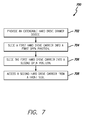
- FIG. 7 is a flow diagram 700 of an example method for using an extendable hard drive drawer.
- the method described below can be carried out using the configurations illustrated in FIGS. 1-6 , for example, and various elements of these figures are referenced in explaining the example method.
- Each block shown in FIG. 7 represents one or more processes, methods or subroutines, carried out in the example method.
- the illustrated order of blocks is illustrative only and the order of the blocks can change according to the present disclosure. Additional blocks can be added or fewer blocks may be utilized, without departing from this disclosure.
- the example method begins at block 702.
- an extendable hard drive drawer device can be a chassis comprising a front side and a rear side, the first hard drive carrier and the second hard drive carrier housed within the chassis, the first hard drive carrier housed at the front side, the second hard drive carrier housed behind the first hard drive carrier, the first hard drive carrier and the second hard drive carrier slidably coupled to the chassis, the first hard drive carrier and the second hard drive carrier each adapted to house at least one hard drive, and the first hard drive carrier adapted to slide from a first closed position to a first open position, and from the first open position to a second open position, such that the second hard drive carrier can be accessed in the second open position.
- the device can be structured according any of the described implementations above for cable storage under a drawer.
- the first hard drive carrier is slid to the first open position.
- the first hard drive carrier is slid a maximum distance apart from the second hard drive carrier.
- the maximum distance can be a fixed position.
- the first hard drive carrier can be extended outside of a chassis at the first open position.
- the first hard drive carrier is slid to the second open position.
- the first and second hard drive carriers are slid outwards from the chassis such that the second hard drive carrier is at the front of the chassis.
- the second hard drive carrier is accessed from the front side.
- the hard drives of the second hard drive carrier can be accessed from the front side for the purposes of repair, replacement, and maintenance.
- apparatuses comprising multiple chasses and hard drive drawers can be supported by the above disclosure.
- multiple hard drive drawers e.g., three or more hard drive drawers
- the drawers can house computing components other than hard drives.
- the drawers can house any combination of hard drives, RAM, ROM, chipsets, PCI cards, etc.
Landscapes
- Engineering & Computer Science (AREA)
- Microelectronics & Electronic Packaging (AREA)
- Computer Hardware Design (AREA)
- General Engineering & Computer Science (AREA)
- Drawers Of Furniture (AREA)
- Casings For Electric Apparatus (AREA)
- Warehouses Or Storage Devices (AREA)
- Cooling Or The Like Of Electrical Apparatus (AREA)
Applications Claiming Priority (1)
| Application Number | Priority Date | Filing Date | Title |
|---|---|---|---|
| TW103101638A TWI574602B (zh) | 2014-01-16 | 2014-01-16 | 伺服器 |
Publications (3)
| Publication Number | Publication Date |
|---|---|
| EP2897128A2 true EP2897128A2 (de) | 2015-07-22 |
| EP2897128A3 EP2897128A3 (de) | 2015-08-05 |
| EP2897128B1 EP2897128B1 (de) | 2019-06-05 |
Family
ID=52292724
Family Applications (1)
| Application Number | Title | Priority Date | Filing Date |
|---|---|---|---|
| EP14200695.6A Active EP2897128B1 (de) | 2014-01-16 | 2014-12-31 | Ausziehbare Festplattenschublade |
Country Status (5)
| Country | Link |
|---|---|
| US (2) | US9763352B2 (de) |
| EP (1) | EP2897128B1 (de) |
| JP (1) | JP5711401B1 (de) |
| CN (1) | CN104793708B (de) |
| TW (1) | TWI574602B (de) |
Cited By (2)
| Publication number | Priority date | Publication date | Assignee | Title |
|---|---|---|---|---|
| WO2017127066A1 (en) * | 2016-01-20 | 2017-07-27 | Hewlett Packard Enterprise Development Lp | Removeable wall |
| EP4401519A1 (de) * | 2023-01-13 | 2024-07-17 | King Slide Works Co., Ltd. | Gleitschienenmechanismus |
Families Citing this family (25)
| Publication number | Priority date | Publication date | Assignee | Title |
|---|---|---|---|---|
| TWM441186U (en) | 2012-06-25 | 2012-11-11 | Quanta Comp Inc | Tray device |
| TWI574602B (zh) * | 2014-01-16 | 2017-03-11 | 廣達電腦股份有限公司 | 伺服器 |
| WO2016018407A1 (en) * | 2014-07-31 | 2016-02-04 | Hewlett-Packard Development Company, L.P. | Mounting assembly |
| CN105448308B (zh) | 2014-08-27 | 2019-04-09 | 祥和科技有限公司 | 用于形成具有延长高度的硬盘驱动器基板的方法和装置 |
| US9420718B2 (en) * | 2014-11-19 | 2016-08-16 | Dell Products, L.P. | Adjustable device carrier for modular chassis |
| CN105700637A (zh) * | 2014-11-27 | 2016-06-22 | 英业达科技有限公司 | 服务器机箱 |
| CN104503550A (zh) * | 2014-12-04 | 2015-04-08 | 英业达科技有限公司 | 服务器装置 |
| JP6558085B2 (ja) * | 2015-06-08 | 2019-08-14 | 富士通株式会社 | ストレージ装置 |
| US9933823B2 (en) * | 2015-09-24 | 2018-04-03 | Quanta Computer Inc. | Component tray holder with slim side rails |
| CN107402604A (zh) * | 2016-05-20 | 2017-11-28 | 环旭电子股份有限公司 | 服务器机壳之轨道组 |
| CN106200818A (zh) * | 2016-06-28 | 2016-12-07 | 英业达科技有限公司 | 服务器 |
| TWI616131B (zh) * | 2016-08-31 | 2018-02-21 | 川湖科技股份有限公司 | 理線裝置 |
| CN108628411B (zh) * | 2017-03-23 | 2019-09-20 | 鸿富锦精密电子(天津)有限公司 | 机箱 |
| JP6907675B2 (ja) * | 2017-04-19 | 2021-07-21 | 富士通株式会社 | 情報処理装置 |
| TWM563727U (zh) | 2018-04-18 | 2018-07-11 | 勤誠興業股份有限公司 | 容納機構及其托架 |
| US20210177112A1 (en) * | 2018-06-18 | 2021-06-17 | Frank F. E. MAYER | Holding device for cards and/or bank notes |
| CN110647217B (zh) * | 2018-06-27 | 2023-02-03 | 富联精密电子(天津)有限公司 | 盖板及采用该盖板的机箱 |
| CN109104836A (zh) * | 2018-08-15 | 2018-12-28 | 英业达科技有限公司 | 服务器 |
| CN109407770B (zh) * | 2018-09-21 | 2021-09-28 | 英业达科技有限公司 | 服务器 |
| TWI700978B (zh) * | 2019-04-23 | 2020-08-01 | 川湖科技股份有限公司 | 滑軌總成 |
| US11262809B2 (en) * | 2019-05-10 | 2022-03-01 | Hewlett Packard Enterprise Development Lp | Base chassis including extension to support additional storage cage |
| USD1085091S1 (en) * | 2020-02-14 | 2025-07-22 | Y.E. Hub Armenia LLC | Data processing device |
| TWI768882B (zh) * | 2021-05-07 | 2022-06-21 | 緯穎科技服務股份有限公司 | 具有伸縮裝置的伺服器機箱、及具有伸縮裝置的伺服器 |
| CN115705081A (zh) * | 2021-08-16 | 2023-02-17 | 纬联电子科技(中山)有限公司 | 托盘模块及具有该托盘模块的服务器 |
| US12360578B2 (en) * | 2023-02-27 | 2025-07-15 | Hewlett Packard Enterprise Development Lp | Drive adaptor for a drive carrier |
Family Cites Families (42)
| Publication number | Priority date | Publication date | Assignee | Title |
|---|---|---|---|---|
| US5187643A (en) | 1992-02-04 | 1993-02-16 | Shou Tsai I | Computer mounting structure for a detachable hard disk drive |
| US5460441A (en) * | 1994-11-01 | 1995-10-24 | Compaq Computer Corporation | Rack-mounted computer apparatus |
| US5940355A (en) | 1996-03-29 | 1999-08-17 | Cygnet Storage Solutions | Data storage device including a transport mechanism for moving disk storage media between a plurality of removable magazines and a disk drive |
| US5949645A (en) | 1997-06-02 | 1999-09-07 | Northern Telecom Limited | Electronic unit |
| US6025989A (en) | 1998-04-21 | 2000-02-15 | International Business Machines Corporation | Modular node assembly for rack mounted multiprocessor computer |
| US6813113B1 (en) | 1999-02-25 | 2004-11-02 | Hewlett-Packard Development Company, L.P. | Data cartridge import/export drawer having three-element, two-configuration slide |
| US6685033B1 (en) * | 2000-03-03 | 2004-02-03 | Dell Products L.P. | System and apparatus enabling top, front and rear access to a rack mounted computer device |
| US6648428B2 (en) | 2001-04-18 | 2003-11-18 | Hewlett-Packard Development Company, L.P. | Reconfigurable data cartridge import/export drawer |
| TWI220942B (en) * | 2001-06-01 | 2004-09-11 | Wistron Corp | Hard disk retraction mechanism |
| JP3698360B2 (ja) * | 2001-07-13 | 2005-09-21 | インターナショナル・ビジネス・マシーンズ・コーポレーション | 電子機器および電子機器を格納したラック |
| US6520346B1 (en) * | 2001-07-24 | 2003-02-18 | Cheng Kuo Liu | Modularized structure for industrial rack |
| TW590256U (en) | 2003-03-28 | 2004-06-01 | Hon Hai Prec Ind Co Ltd | A storage mounting assembly |
| US7916423B2 (en) * | 2006-03-31 | 2011-03-29 | Spectra Logic Corporation | High density array system with active movable media drawers |
| CN200997298Y (zh) * | 2006-12-28 | 2007-12-26 | 友讯科技股份有限公司 | 硬盘抽取盒 |
| US7983032B2 (en) * | 2007-10-05 | 2011-07-19 | Jabil Circuit, Inc. | Incorporation of two or more hard disk drives into a single drive carrier with a single midplane connector |
| US8107256B1 (en) | 2007-10-26 | 2012-01-31 | Solace Systems, Inc. | Serviceable networking appliance chassis |
| TWI446852B (zh) * | 2008-09-30 | 2014-07-21 | Ibm | 閂鎖機構 |
| WO2010080150A1 (en) * | 2009-01-08 | 2010-07-15 | Hewlett-Packard Development Company, L.P. | Computer including hot-pluggable disk storage drives that are mounted in an in-line arrangement |
| WO2010087023A1 (ja) * | 2009-02-02 | 2010-08-05 | 富士通株式会社 | ディスク搭載装置 |
| TWI358016B (en) * | 2009-04-17 | 2012-02-11 | Inventec Corp | Server |
| JP4816758B2 (ja) | 2009-04-24 | 2011-11-16 | 日本電気株式会社 | 磁気テープライブラリ装置 |
| CN101963831B (zh) * | 2009-07-21 | 2012-07-04 | 英业达股份有限公司 | 具有储存阵列模块的服务器装置 |
| US8462502B2 (en) | 2010-11-09 | 2013-06-11 | Hitachi, Ltd. | Structural fabric of a storage apparatus for mounting storage devices |
| GB201107860D0 (en) | 2011-05-11 | 2011-06-22 | Manda Ion | Rack module |
| US8857927B2 (en) | 2012-01-04 | 2014-10-14 | Haworth, Inc. | Drawer insert for file cabinet |
| US9007766B2 (en) | 2012-04-10 | 2015-04-14 | Xyratex Technology Limited | Storage enclosure with pivotably mounted midplane assembly |
| US8897017B2 (en) | 2012-06-18 | 2014-11-25 | Facebook, Inc. | Serviceable hard disk drive trays for a server rack |
| TWM441186U (en) * | 2012-06-25 | 2012-11-11 | Quanta Comp Inc | Tray device |
| CN202711148U (zh) * | 2012-07-20 | 2013-01-30 | 广达电脑股份有限公司 | 托盘装置 |
| TW201417097A (zh) | 2012-10-31 | 2014-05-01 | Hon Hai Prec Ind Co Ltd | 電子裝置殼體 |
| CN103853256B (zh) * | 2012-12-07 | 2018-10-23 | 鸿富锦精密电子(天津)有限公司 | 机柜式服务器 |
| US9456515B2 (en) | 2013-01-23 | 2016-09-27 | Seagate Technology Llc | Storage enclosure with independent storage device drawers |
| TWI517780B (zh) * | 2013-03-27 | 2016-01-11 | 廣達電腦股份有限公司 | 伺服器機櫃及其伺服器裝置 |
| TWI537938B (zh) * | 2013-05-16 | 2016-06-11 | 廣達電腦股份有限公司 | 儲存陣列模組及其硬碟容置單元 |
| US9245587B2 (en) * | 2013-07-10 | 2016-01-26 | Super Micro Computer Inc. | Server device and data storage device replacement mechanism thereof |
| TWI574602B (zh) * | 2014-01-16 | 2017-03-11 | 廣達電腦股份有限公司 | 伺服器 |
| TW201531205A (zh) * | 2014-01-22 | 2015-08-01 | Quanta Comp Inc | 伺服器裝置 |
| CN104932625B (zh) * | 2014-03-18 | 2018-03-20 | 鸿富锦精密电子(天津)有限公司 | 电子装置 |
| WO2016018407A1 (en) * | 2014-07-31 | 2016-02-04 | Hewlett-Packard Development Company, L.P. | Mounting assembly |
| CN104375595B (zh) * | 2014-11-10 | 2017-09-19 | 英业达科技有限公司 | 一种免工具安装硬盘装置 |
| CN104536539A (zh) * | 2014-12-04 | 2015-04-22 | 英业达科技有限公司 | 电子装置 |
| US9335798B1 (en) * | 2015-04-21 | 2016-05-10 | Aic Inc. | Assembly structure for data storage device of server |
-
2014
- 2014-01-16 TW TW103101638A patent/TWI574602B/zh active
- 2014-01-28 CN CN201410043980.3A patent/CN104793708B/zh active Active
- 2014-04-14 JP JP2014082794A patent/JP5711401B1/ja active Active
- 2014-12-31 EP EP14200695.6A patent/EP2897128B1/de active Active
-
2015
- 2015-01-09 US US14/593,119 patent/US9763352B2/en active Active
-
2017
- 2017-06-30 US US15/639,064 patent/US10127948B1/en active Active
Non-Patent Citations (1)
| Title |
|---|
| None |
Cited By (4)
| Publication number | Priority date | Publication date | Assignee | Title |
|---|---|---|---|---|
| WO2017127066A1 (en) * | 2016-01-20 | 2017-07-27 | Hewlett Packard Enterprise Development Lp | Removeable wall |
| US10649504B2 (en) | 2016-01-20 | 2020-05-12 | Hewlett Packard Enterprise Development Lp | Removeable wall |
| EP4401519A1 (de) * | 2023-01-13 | 2024-07-17 | King Slide Works Co., Ltd. | Gleitschienenmechanismus |
| US12268301B2 (en) | 2023-01-13 | 2025-04-08 | King Slide Works Co., Ltd. | Slide rail mechanism |
Also Published As
| Publication number | Publication date |
|---|---|
| TWI574602B (zh) | 2017-03-11 |
| US20150201522A1 (en) | 2015-07-16 |
| JP5711401B1 (ja) | 2015-04-30 |
| JP2015135654A (ja) | 2015-07-27 |
| EP2897128B1 (de) | 2019-06-05 |
| TW201531204A (zh) | 2015-08-01 |
| EP2897128A3 (de) | 2015-08-05 |
| CN104793708B (zh) | 2018-08-31 |
| CN104793708A (zh) | 2015-07-22 |
| US9763352B2 (en) | 2017-09-12 |
| US10127948B1 (en) | 2018-11-13 |
| US20180330762A1 (en) | 2018-11-15 |
Similar Documents
| Publication | Publication Date | Title |
|---|---|---|
| US10127948B1 (en) | Extendable hard drive drawer | |
| US8456844B2 (en) | Adjustable mount assembly | |
| JP5681324B2 (ja) | 棚取付型モジュール式コンピューティング・ユニット | |
| US9304556B2 (en) | Hard drive tray device | |
| CA2858200C (en) | Partial-width rack-mounted computing devices | |
| US9609778B1 (en) | Server having a latch | |
| US10334746B2 (en) | Component mounting assembly | |
| US9756745B2 (en) | Chassis drawer for modular information handling resources | |
| US7999179B2 (en) | Biased air baffle for computer rack | |
| US9229492B2 (en) | Adaptive information handling system rack rail mount | |
| US20150163946A1 (en) | Chassis drawer for modular information handling resources | |
| US9383784B2 (en) | Method and apparatus housing a hard-disk drive using a tray with anchoring strips | |
| EP2940689B1 (de) | Kabelaufbewahrung unter einer schublade | |
| TWI602487B (zh) | 用於伺服器機架的高密度機殼 | |
| CN102202483A (zh) | 托架 | |
| CN105404363A (zh) | 机壳 | |
| US20190171257A1 (en) | Mounting assembly | |
| US10834842B1 (en) | Rack-mountable assembly with spring-hinged mounting bracket(s) | |
| US9990011B2 (en) | Drive array | |
| CN104105367A (zh) | 机柜式服务器及其挡风装置 | |
| CN102841651A (zh) | 数据存取器固定装置 | |
| US20150163948A1 (en) | Backplane for electrically coupling modular information handling resources to one or more other information handling resources | |
| CN217108867U (zh) | 置物支架 | |
| CN223041142U (zh) | 一种方便安装的抽屉式机架 | |
| CN213096788U (zh) | 一种设计用工作平台 |
Legal Events
| Date | Code | Title | Description |
|---|---|---|---|
| PUAL | Search report despatched |
Free format text: ORIGINAL CODE: 0009013 |
|
| PUAI | Public reference made under article 153(3) epc to a published international application that has entered the european phase |
Free format text: ORIGINAL CODE: 0009012 |
|
| 17P | Request for examination filed |
Effective date: 20141231 |
|
| AK | Designated contracting states |
Kind code of ref document: A2 Designated state(s): AL AT BE BG CH CY CZ DE DK EE ES FI FR GB GR HR HU IE IS IT LI LT LU LV MC MK MT NL NO PL PT RO RS SE SI SK SM TR |
|
| AX | Request for extension of the european patent |
Extension state: BA ME |
|
| AK | Designated contracting states |
Kind code of ref document: A3 Designated state(s): AL AT BE BG CH CY CZ DE DK EE ES FI FR GB GR HR HU IE IS IT LI LT LU LV MC MK MT NL NO PL PT RO RS SE SI SK SM TR |
|
| AX | Request for extension of the european patent |
Extension state: BA ME |
|
| RIC1 | Information provided on ipc code assigned before grant |
Ipc: G11B 33/12 20060101AFI20150701BHEP |
|
| 17P | Request for examination filed |
Effective date: 20151130 |
|
| RBV | Designated contracting states (corrected) |
Designated state(s): AL AT BE BG CH CY CZ DE DK EE ES FI FR GB GR HR HU IE IS IT LI LT LU LV MC MK MT NL NO PL PT RO RS SE SI SK SM TR |
|
| 17Q | First examination report despatched |
Effective date: 20161006 |
|
| STAA | Information on the status of an ep patent application or granted ep patent |
Free format text: STATUS: EXAMINATION IS IN PROGRESS |
|
| GRAP | Despatch of communication of intention to grant a patent |
Free format text: ORIGINAL CODE: EPIDOSNIGR1 |
|
| STAA | Information on the status of an ep patent application or granted ep patent |
Free format text: STATUS: GRANT OF PATENT IS INTENDED |
|
| INTG | Intention to grant announced |
Effective date: 20181221 |
|
| GRAS | Grant fee paid |
Free format text: ORIGINAL CODE: EPIDOSNIGR3 |
|
| GRAA | (expected) grant |
Free format text: ORIGINAL CODE: 0009210 |
|
| STAA | Information on the status of an ep patent application or granted ep patent |
Free format text: STATUS: THE PATENT HAS BEEN GRANTED |
|
| RAP1 | Party data changed (applicant data changed or rights of an application transferred) |
Owner name: QUANTA COMPUTER, INC |
|
| RIN1 | Information on inventor provided before grant (corrected) |
Inventor name: CHENG, I-LANG Inventor name: JAU, MAW-ZAN Inventor name: TSORNG, YAW-TZORNG Inventor name: CHEN, CHAO-JUNG |
|
| AK | Designated contracting states |
Kind code of ref document: B1 Designated state(s): AL AT BE BG CH CY CZ DE DK EE ES FI FR GB GR HR HU IE IS IT LI LT LU LV MC MK MT NL NO PL PT RO RS SE SI SK SM TR |
|
| REG | Reference to a national code |
Ref country code: GB Ref legal event code: FG4D |
|
| REG | Reference to a national code |
Ref country code: CH Ref legal event code: EP |
|
| REG | Reference to a national code |
Ref country code: AT Ref legal event code: REF Ref document number: 1140803 Country of ref document: AT Kind code of ref document: T Effective date: 20190615 |
|
| REG | Reference to a national code |
Ref country code: IE Ref legal event code: FG4D |
|
| REG | Reference to a national code |
Ref country code: DE Ref legal event code: R096 Ref document number: 602014047776 Country of ref document: DE |
|
| REG | Reference to a national code |
Ref country code: NL Ref legal event code: MP Effective date: 20190605 |
|
| REG | Reference to a national code |
Ref country code: LT Ref legal event code: MG4D |
|
| PG25 | Lapsed in a contracting state [announced via postgrant information from national office to epo] |
Ref country code: FI Free format text: LAPSE BECAUSE OF FAILURE TO SUBMIT A TRANSLATION OF THE DESCRIPTION OR TO PAY THE FEE WITHIN THE PRESCRIBED TIME-LIMIT Effective date: 20190605 Ref country code: NO Free format text: LAPSE BECAUSE OF FAILURE TO SUBMIT A TRANSLATION OF THE DESCRIPTION OR TO PAY THE FEE WITHIN THE PRESCRIBED TIME-LIMIT Effective date: 20190905 Ref country code: ES Free format text: LAPSE BECAUSE OF FAILURE TO SUBMIT A TRANSLATION OF THE DESCRIPTION OR TO PAY THE FEE WITHIN THE PRESCRIBED TIME-LIMIT Effective date: 20190605 Ref country code: SE Free format text: LAPSE BECAUSE OF FAILURE TO SUBMIT A TRANSLATION OF THE DESCRIPTION OR TO PAY THE FEE WITHIN THE PRESCRIBED TIME-LIMIT Effective date: 20190605 Ref country code: AL Free format text: LAPSE BECAUSE OF FAILURE TO SUBMIT A TRANSLATION OF THE DESCRIPTION OR TO PAY THE FEE WITHIN THE PRESCRIBED TIME-LIMIT Effective date: 20190605 Ref country code: HR Free format text: LAPSE BECAUSE OF FAILURE TO SUBMIT A TRANSLATION OF THE DESCRIPTION OR TO PAY THE FEE WITHIN THE PRESCRIBED TIME-LIMIT Effective date: 20190605 Ref country code: LT Free format text: LAPSE BECAUSE OF FAILURE TO SUBMIT A TRANSLATION OF THE DESCRIPTION OR TO PAY THE FEE WITHIN THE PRESCRIBED TIME-LIMIT Effective date: 20190605 |
|
| PG25 | Lapsed in a contracting state [announced via postgrant information from national office to epo] |
Ref country code: RS Free format text: LAPSE BECAUSE OF FAILURE TO SUBMIT A TRANSLATION OF THE DESCRIPTION OR TO PAY THE FEE WITHIN THE PRESCRIBED TIME-LIMIT Effective date: 20190605 Ref country code: BG Free format text: LAPSE BECAUSE OF FAILURE TO SUBMIT A TRANSLATION OF THE DESCRIPTION OR TO PAY THE FEE WITHIN THE PRESCRIBED TIME-LIMIT Effective date: 20190905 Ref country code: GR Free format text: LAPSE BECAUSE OF FAILURE TO SUBMIT A TRANSLATION OF THE DESCRIPTION OR TO PAY THE FEE WITHIN THE PRESCRIBED TIME-LIMIT Effective date: 20190906 Ref country code: LV Free format text: LAPSE BECAUSE OF FAILURE TO SUBMIT A TRANSLATION OF THE DESCRIPTION OR TO PAY THE FEE WITHIN THE PRESCRIBED TIME-LIMIT Effective date: 20190605 |
|
| REG | Reference to a national code |
Ref country code: AT Ref legal event code: MK05 Ref document number: 1140803 Country of ref document: AT Kind code of ref document: T Effective date: 20190605 |
|
| PG25 | Lapsed in a contracting state [announced via postgrant information from national office to epo] |
Ref country code: RO Free format text: LAPSE BECAUSE OF FAILURE TO SUBMIT A TRANSLATION OF THE DESCRIPTION OR TO PAY THE FEE WITHIN THE PRESCRIBED TIME-LIMIT Effective date: 20190605 Ref country code: SK Free format text: LAPSE BECAUSE OF FAILURE TO SUBMIT A TRANSLATION OF THE DESCRIPTION OR TO PAY THE FEE WITHIN THE PRESCRIBED TIME-LIMIT Effective date: 20190605 Ref country code: CZ Free format text: LAPSE BECAUSE OF FAILURE TO SUBMIT A TRANSLATION OF THE DESCRIPTION OR TO PAY THE FEE WITHIN THE PRESCRIBED TIME-LIMIT Effective date: 20190605 Ref country code: EE Free format text: LAPSE BECAUSE OF FAILURE TO SUBMIT A TRANSLATION OF THE DESCRIPTION OR TO PAY THE FEE WITHIN THE PRESCRIBED TIME-LIMIT Effective date: 20190605 Ref country code: AT Free format text: LAPSE BECAUSE OF FAILURE TO SUBMIT A TRANSLATION OF THE DESCRIPTION OR TO PAY THE FEE WITHIN THE PRESCRIBED TIME-LIMIT Effective date: 20190605 Ref country code: NL Free format text: LAPSE BECAUSE OF FAILURE TO SUBMIT A TRANSLATION OF THE DESCRIPTION OR TO PAY THE FEE WITHIN THE PRESCRIBED TIME-LIMIT Effective date: 20190605 Ref country code: PT Free format text: LAPSE BECAUSE OF FAILURE TO SUBMIT A TRANSLATION OF THE DESCRIPTION OR TO PAY THE FEE WITHIN THE PRESCRIBED TIME-LIMIT Effective date: 20191007 |
|
| PG25 | Lapsed in a contracting state [announced via postgrant information from national office to epo] |
Ref country code: IT Free format text: LAPSE BECAUSE OF FAILURE TO SUBMIT A TRANSLATION OF THE DESCRIPTION OR TO PAY THE FEE WITHIN THE PRESCRIBED TIME-LIMIT Effective date: 20190605 Ref country code: IS Free format text: LAPSE BECAUSE OF FAILURE TO SUBMIT A TRANSLATION OF THE DESCRIPTION OR TO PAY THE FEE WITHIN THE PRESCRIBED TIME-LIMIT Effective date: 20191005 Ref country code: SM Free format text: LAPSE BECAUSE OF FAILURE TO SUBMIT A TRANSLATION OF THE DESCRIPTION OR TO PAY THE FEE WITHIN THE PRESCRIBED TIME-LIMIT Effective date: 20190605 |
|
| REG | Reference to a national code |
Ref country code: DE Ref legal event code: R097 Ref document number: 602014047776 Country of ref document: DE |
|
| PG25 | Lapsed in a contracting state [announced via postgrant information from national office to epo] |
Ref country code: TR Free format text: LAPSE BECAUSE OF FAILURE TO SUBMIT A TRANSLATION OF THE DESCRIPTION OR TO PAY THE FEE WITHIN THE PRESCRIBED TIME-LIMIT Effective date: 20190605 |
|
| PLBE | No opposition filed within time limit |
Free format text: ORIGINAL CODE: 0009261 |
|
| STAA | Information on the status of an ep patent application or granted ep patent |
Free format text: STATUS: NO OPPOSITION FILED WITHIN TIME LIMIT |
|
| PG25 | Lapsed in a contracting state [announced via postgrant information from national office to epo] |
Ref country code: PL Free format text: LAPSE BECAUSE OF FAILURE TO SUBMIT A TRANSLATION OF THE DESCRIPTION OR TO PAY THE FEE WITHIN THE PRESCRIBED TIME-LIMIT Effective date: 20190605 Ref country code: DK Free format text: LAPSE BECAUSE OF FAILURE TO SUBMIT A TRANSLATION OF THE DESCRIPTION OR TO PAY THE FEE WITHIN THE PRESCRIBED TIME-LIMIT Effective date: 20190605 |
|
| 26N | No opposition filed |
Effective date: 20200306 |
|
| PG25 | Lapsed in a contracting state [announced via postgrant information from national office to epo] |
Ref country code: SI Free format text: LAPSE BECAUSE OF FAILURE TO SUBMIT A TRANSLATION OF THE DESCRIPTION OR TO PAY THE FEE WITHIN THE PRESCRIBED TIME-LIMIT Effective date: 20190605 |
|
| REG | Reference to a national code |
Ref country code: CH Ref legal event code: PL |
|
| REG | Reference to a national code |
Ref country code: BE Ref legal event code: MM Effective date: 20191231 |
|
| PG25 | Lapsed in a contracting state [announced via postgrant information from national office to epo] |
Ref country code: MC Free format text: LAPSE BECAUSE OF FAILURE TO SUBMIT A TRANSLATION OF THE DESCRIPTION OR TO PAY THE FEE WITHIN THE PRESCRIBED TIME-LIMIT Effective date: 20190605 |
|
| PG25 | Lapsed in a contracting state [announced via postgrant information from national office to epo] |
Ref country code: IE Free format text: LAPSE BECAUSE OF NON-PAYMENT OF DUE FEES Effective date: 20191231 Ref country code: LU Free format text: LAPSE BECAUSE OF NON-PAYMENT OF DUE FEES Effective date: 20191231 |
|
| PG25 | Lapsed in a contracting state [announced via postgrant information from national office to epo] |
Ref country code: BE Free format text: LAPSE BECAUSE OF NON-PAYMENT OF DUE FEES Effective date: 20191231 Ref country code: CH Free format text: LAPSE BECAUSE OF NON-PAYMENT OF DUE FEES Effective date: 20191231 Ref country code: LI Free format text: LAPSE BECAUSE OF NON-PAYMENT OF DUE FEES Effective date: 20191231 |
|
| PG25 | Lapsed in a contracting state [announced via postgrant information from national office to epo] |
Ref country code: CY Free format text: LAPSE BECAUSE OF FAILURE TO SUBMIT A TRANSLATION OF THE DESCRIPTION OR TO PAY THE FEE WITHIN THE PRESCRIBED TIME-LIMIT Effective date: 20190605 |
|
| PG25 | Lapsed in a contracting state [announced via postgrant information from national office to epo] |
Ref country code: HU Free format text: LAPSE BECAUSE OF FAILURE TO SUBMIT A TRANSLATION OF THE DESCRIPTION OR TO PAY THE FEE WITHIN THE PRESCRIBED TIME-LIMIT; INVALID AB INITIO Effective date: 20141231 Ref country code: MT Free format text: LAPSE BECAUSE OF FAILURE TO SUBMIT A TRANSLATION OF THE DESCRIPTION OR TO PAY THE FEE WITHIN THE PRESCRIBED TIME-LIMIT Effective date: 20190605 |
|
| PG25 | Lapsed in a contracting state [announced via postgrant information from national office to epo] |
Ref country code: MK Free format text: LAPSE BECAUSE OF FAILURE TO SUBMIT A TRANSLATION OF THE DESCRIPTION OR TO PAY THE FEE WITHIN THE PRESCRIBED TIME-LIMIT Effective date: 20190605 |
|
| PGFP | Annual fee paid to national office [announced via postgrant information from national office to epo] |
Ref country code: DE Payment date: 20251104 Year of fee payment: 12 |
|
| PGFP | Annual fee paid to national office [announced via postgrant information from national office to epo] |
Ref country code: GB Payment date: 20251114 Year of fee payment: 12 |
|
| PGFP | Annual fee paid to national office [announced via postgrant information from national office to epo] |
Ref country code: FR Payment date: 20251110 Year of fee payment: 12 |