EP2897145A1 - Schalter - Google Patents
Schalter Download PDFInfo
- Publication number
- EP2897145A1 EP2897145A1 EP13837986.2A EP13837986A EP2897145A1 EP 2897145 A1 EP2897145 A1 EP 2897145A1 EP 13837986 A EP13837986 A EP 13837986A EP 2897145 A1 EP2897145 A1 EP 2897145A1
- Authority
- EP
- European Patent Office
- Prior art keywords
- plate
- switch body
- terminal
- switch
- portions
- Prior art date
- Legal status (The legal status is an assumption and is not a legal conclusion. Google has not performed a legal analysis and makes no representation as to the accuracy of the status listed.)
- Withdrawn
Links
- 238000012423 maintenance Methods 0.000 abstract description 5
- 238000003780 insertion Methods 0.000 description 18
- 230000037431 insertion Effects 0.000 description 18
- 239000002184 metal Substances 0.000 description 16
- 230000002093 peripheral effect Effects 0.000 description 5
- 229920003002 synthetic resin Polymers 0.000 description 3
- 239000000057 synthetic resin Substances 0.000 description 3
- 239000011248 coating agent Substances 0.000 description 2
- 238000000576 coating method Methods 0.000 description 2
- 238000000034 method Methods 0.000 description 2
- 238000012986 modification Methods 0.000 description 1
- 230000004048 modification Effects 0.000 description 1
- 238000000465 moulding Methods 0.000 description 1
Images


Classifications
-
- H—ELECTRICITY
- H01—ELECTRIC ELEMENTS
- H01H—ELECTRIC SWITCHES; RELAYS; SELECTORS; EMERGENCY PROTECTIVE DEVICES
- H01H23/00—Tumbler or rocker switches, i.e. switches characterised by being operated by rocking an operating member in the form of a rocker button
- H01H23/02—Details
- H01H23/12—Movable parts; Contacts mounted thereon
- H01H23/14—Tumblers
- H01H23/143—Tumblers having a generally flat elongated shape
-
- H—ELECTRICITY
- H01—ELECTRIC ELEMENTS
- H01H—ELECTRIC SWITCHES; RELAYS; SELECTORS; EMERGENCY PROTECTIVE DEVICES
- H01H23/00—Tumbler or rocker switches, i.e. switches characterised by being operated by rocking an operating member in the form of a rocker button
- H01H23/02—Details
- H01H23/12—Movable parts; Contacts mounted thereon
- H01H23/16—Driving mechanisms
- H01H23/20—Driving mechanisms having snap action
- H01H23/205—Driving mechanisms having snap action using a compression spring between tumbler and an articulated contact plate
-
- H—ELECTRICITY
- H01—ELECTRIC ELEMENTS
- H01H—ELECTRIC SWITCHES; RELAYS; SELECTORS; EMERGENCY PROTECTIVE DEVICES
- H01H23/00—Tumbler or rocker switches, i.e. switches characterised by being operated by rocking an operating member in the form of a rocker button
- H01H23/02—Details
- H01H23/04—Cases; Covers
Definitions
- the invention relates to a switch.
- a switch which includes: a switch body to be embedded in an embedding hole provided in a wall member; and a plate to be fixed to the wall member while being detachably attached to the switch body (e.g., see paragraphs 0035 and 0036, and Fig. 9 in JP 2001-325846 A ).
- the plate has a through-hole through which the switch body is inserted.
- a switch body 80 is detachably attached to a plate 82 by engagement projections 81, 81 provided at the switch body 80 being respectively engaged with engagement recesses 84, 84 provided in an inner peripheral surface of a through-hole 83 of the plate 82.
- a switch of the present invention includes a switch body and a plate.
- the switch body is configured to be embedded in an embedding hole provided in a wall member.
- the plate is configured to be fixed to the wall member while being detachably attached to the switch body.
- the plate has a through-hole through which the switch body is inserted.
- the plate is provided at portions thereof, facing each other across the switch body, with engagement projections, respectively.
- the switch body is provided with engagement recesses. The switch body and the plate are configured to be attached to each other by the engagement projections being respectively engaged with the engagement recesses.
- the engagement projections which may be relatively likely to be damaged when attachment and detachment of the switch body with respect to the plate are repeated, are provided at the plate that is generally more inexpensive than the switch body. Therefore, it is possible to more reduce the maintenance cost, compared with a case where the engagement projections are provided on the switch body side.
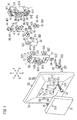
- Figs. 1 to 6 show a switch of the present embodiment.
- A, B, C, D, E and F-directions shown in Fig. 2 are referred to as up, down, left, right, front and back directions, respectively.
- an up-down direction corresponds to an axis direction of a terminal screw 44 described later.
- An up direction corresponds to a direction (a first direction) in which a first terminal nut 431 is moved when a first terminal screw 451 is tightened, described later.
- a down direction is a direction opposite to the first direction, and corresponds to a direction (a second direction) in which a second terminal nut 432 is moved when a second terminal screw 452 is tightened, described later.
- a right-left direction is orthogonal to the first direction, and is parallel to a surface of a plate 21.
- a left direction (the C-direction) is a left direction (a third direction) when the switch is viewed from the front.
- a right direction (the D-direction) is a direction opposite to the third direction. That is, the right direction is a right direction (a fourth direction) when the switch is viewed from the front.
- a front-back direction is orthogonal to the first and third directions.
- a front direction corresponds to a direction (a fifth direction) in which electric wires are inserted into first and second wire insertion holes 531, 532 described later.
- a back direction (the F-direction) is a direction opposite to the fifth direction, and corresponds to a direction (a sixth direction) in which an operation handle 31 described later is pressed.
- the switch includes a switch body 1, the plate 21, and two metal fittings 22.
- the plate 21 and two metal fittings 22 are used when the switch body 1 is embedded in an embedding hole (not shown) provided in a wall member.
- the switch body 1 includes: a reversal handle 32 that is configured to be turned by receiving operation force via the operation handle 31; and a contactor 40 that includes a movable contact 401 and is configured to be turned together with the reversal handle 32.
- the switch body 1 further includes: a first terminal plate 41 that includes a fulcrum projection 411 as a fulcrum for the contactor 40; and a second terminal plate 42 that includes a fixed contact 421 which the movable contact 401 of the contactor 40 is separated from and comes into contact with.
- the reversal handle 32 is formed of synthetic resin for example.
- the contactor 40, and the first and second terminal plates 41, 42 are respectively formed of metal plates for example.
- the switch body 1 further includes a housing 5 that is constituted by a casing 51 and a cover 52.
- the casing 51 has an opened front surface, and accordingly, is provided with a storage recess 50 into which the contactor 40, and the first and second terminal plates 41, 42 can be housed individually.
- the cover 52 is coupled on a front side of the casing 51, and functions as a fulcrum for the reversal handle 32.
- the casing 51 and cover 52 are formed of synthetic resin for example.
- the casing 51 is provided with two central projections 511, 511 which are respectively projected from central parts, in the up-down direction (the first and second directions), of right and left surfaces of the casing 51. Further, two connection projections 512, 512 are respectively projected on upper and lower sides of the each central projection 511.
- the cover 52 includes a main body 520 that is frame-shaped so as to surround the reversal handle 32, and four connection pieces 521 that are projected rearward. Two of the four connection pieces 521 are arranged in the up-down direction at a right end portion of the main body 520, and the remaining connection pieces 521 are arranged in the up-down direction at a left end portion of the main body 520. Each connection piece 521 is plate-shaped, and its thickness direction is directed toward the right-left direction (the third and fourth directions). Each connection piece 521 is provided with a connection hole 522 through the right-left direction, into which a corresponding connection projection 512 is engaged.
- connection projections 512 are respectively engaged into two corresponding connection holes 522 while two connection pieces 521, 521 hold a corresponding central projection 511 therebetween, and accordingly, the casing 51 and the cover 52 are connected with each other.
- end portions (rear end portions) of the connection pieces 521 are elastically deformed to be displaced outward in the right-left direction with respect to base portions (front end portions) thereof, the connection projections 512 can be engaged into or disengaged from the connection holes 522.
- the reversal handle 32 includes a main body 320 that has a rectangular parallelepiped shape as the whole, and two fulcrum projections 321, 321 that are respectively projected outward in the right-left direction from right and left surfaces of the main body 320.
- the cover 52 further includes two fulcrum receiving portions 523, 523 that are projected forward from right and left end portions of the main body 520.
- the respective fulcrum receiving portions 523, 523 are provided in inner surfaces thereof in the right-left direction with recesses.
- the reversal handle 32 is capable of being turned with respect to the cover 52 so that upper and lower end portions of the reversal handle are displaced in the front-back direction (the fifth and sixth directions) with respect to a central portion of the reversal handle, by the respective fulcrum projections 321 abutting on front end portions of the fulcrum receiving portions 523 from the back side.
- the operation handle 31 is provided in a rear surface thereof with a fitting recess 310 (see Fig. 6 ) into which a front end portion of the reversal handle 32 is fitted.
- the reversal handle 32 is provided with two engagement protruding portions 322, 322 that are protruded from upper and lower surfaces of the reversal handle 32, respectively.
- the operation handle 31 is integrated with the reversal handle 32, by the respective engagement protruding portions 322 being engaged into two engagement recessed portions 312, 312 provided on upper and lower sides of an inner peripheral surface of the fitting recess 310.
- the switch body 1 includes a reversal spring 33 as a coil spring.
- One end of the reversal spring 33 is in elastic contact with a rear end of the reversal handle 32, and the other end of the reversal spring 33 is in elastic contact with a front surface of the contactor 40.
- the reversal spring 33 only both end portions thereof are shown in Fig. 5 . Due to spring force of the reversal spring 33, the respective fulcrum projections 321 of the reversal handle 32 are pressed against the fulcrum receiving portions 523 of the cover 52 from the back side, and the contactor 40 is pressed against the fulcrum projection 411 of the first terminal plate 41 from the front side.
- the reversal spring 33 When the upper end portion of the reversal handle 32 is in a state of being projected forward with respect to the housing 5, that is, when the reversal handle 32 is in a state of being inclined counterclockwise as viewed from the right (hereinafter, referred to as an "OFF-state"), the reversal spring 33 is curved so that a central portion thereof is displaced above both end portions thereof in the up-down direction. In the OFF-state, the spring force of the reversal spring 33 is applied to the reversal handle 32 so as to keep the above-mentioned posture of the reversal handle 32.
- the movable contact 401 of the contactor 40 is disposed to face downward, and the fixed contact 421 of the second terminal plate 42 is disposed to face upward.
- the spring force of the reversal spring 33 is applied to the contactor 40 so as to keep a state where the movable contact 401 is separated from the fixed contact 421. That is, in the OFF-state, the first terminal plate 41 is electrically disconnected with the second terminal plate 42.
- the reversal spring 33 is curved so that the central portion thereof is displaced below both end portions thereof in the up-down direction.
- the spring force of the reversal spring 33 is applied to the contactor 40 so as to press the movable contact 401 to the fixed contact 421. That is, in the ON-state, the first terminal plate 41 is electrically connected with the second terminal plate 42 via the contactor 40.
- the operation handle 31 is provided with a mark 311 as a projection, which is disposed at an upper end portion of a front surface of the operation handle 31.
- the front surface is an operation surface for receiving the operation force.
- the upper end portion is displaced backward in the ON-state.
- the mark 311 is not limited to the projection, and may be a recess. Alternatively, the mark 311 may be formed by other method such as printing or two-color molding.
- the storage recess 50 of the casing 51 further stores therein a set of a terminal nut 43 and a terminal screw 44 (hereinafter, referred to as a first terminal nut 431 and a first terminal screw 451) corresponding to the first terminal plate 41, and a set of a terminal nut 43 and a terminal screw 44 (hereinafter, referred to as a second terminal nut 432 and a second terminal screw 452) corresponding to the second terminal plate 42.
- the respective electric wires are connected with the first and second terminal plates 41, 42 via the first terminal nut 431 and first terminal screw 451, and the second terminal nut 432 and second terminal screw 452.
- the first terminal plate 41 is provided with a first contact portion 412 that is inserted between the first terminal nut 431 and a head 441 of the first terminal screw 451 so as to face the first terminal nut 431.
- the second terminal plate 42 is provided with a second contact portion 422 that is inserted between the second terminal nut 432 and a head 441 of the second terminal screw 452 so as to face the second terminal nut 432.
- the first and second contact portions 412, 422 are U-shaped, and have cutout portions 413, 423 provided for avoiding shafts 442 of the first and second terminal screws 451, 452, respectively.
- the storage recess 50 of the casing 51 is provided in an inner peripheral surface thereof with four positioning grooves 56.
- Two of the four positioning grooves 56 are provided so as to correspond to the first terminal plate 41 in right and left inner surfaces of the inner peripheral surface to face each other, respectively.
- the remaining positioning grooves 56 are provided so as to correspond to the second terminal plate 42 in the right and left inner surfaces of the inner peripheral surface to face each other, respectively. It is possible to prevent looseness of the first and second terminal plates 41, 42 to the housing 5, by the respective right and left end portions of the first and second contact portions 412, 422 being inserted into the corresponding positioning grooves 56.
- the respective first and second terminal screws 451, 452 are housed at end portions in the storage recess 50 in the up-down direction, while the axis directions are parallel to the up-down direction and the heads 441 face outward in the up-down direction.
- the storage recess 50 of the casing 51 is provided in a bottom surface thereof with a pair of first wire insertion holes 531, 531 and a pair of second wire insertion holes 532, 532, which are holes through the front-back direction.
- the first wire insertion holes 531, 531 are disposed near the upper side of the storage recess 50 so as to correspond to the first terminal plate 41.
- the second wire insertion holes 532, 532 are disposed near the lower side of the storage recess 50 so as to correspond to the second terminal plate 42.
- the first wire insertion holes 531, 531 are disposed slightly below the first contact portion 412 of the first terminal plate 41.
- the first wire insertion holes 531, 531 are further disposed so that the shaft 442 of the first terminal screw 451 is positioned between the first wire insertion holes 531, 531, when viewed from the front-back direction.
- the second wire insertion holes 532, 532 are disposed slightly above the second contact portion 422 of the second terminal plate 42.
- the second wire insertion holes 532, 532 are further disposed so that the shaft 442 of the second terminal screw 452 is positioned between the second wire insertion holes 532, 532, when viewed from the front-back direction.
- the casing 51 is provided in upper and lower end portions thereof with first and second screw operation holes 541, 542 from which the heads 441 of the first and second terminal screws 451, 452 are exposed, respectively. Accordingly, it is possible to operate the first terminal screw 451, by a screwdriver (not shown) being inserted from the first screw operation hole 541, and similarly, it is possible to operate the second terminal screw 452, by the screwdriver being inserted from the second screw operation hole 542. Sizes and shapes of the first and second screw operation holes 541, 542 are sufficiently reduced to the extent that the heads 441 of the first and second terminal screws 451, 452 cannot pass through the first and second screw operation holes 541, 542.
- the first and second terminal nuts 431, 432 are rectangle-shaped, and is prevented from being turned with respect to the housing 5 (i.e., co-rotation) by abutting on the inner surface of the storage recess 50.
- the switch body 1 When connecting electric wires (not shown) to the switch body 1, a user first sufficiently loosens the first and second terminal screws 451, 452 to move the first terminal nut 431 below the first wire insertion hole 531 and move the second terminal nut 432 above the second wire insertion hole 532.
- the first terminal nut 431 is disposed on the side apart from the first contact portion 412 of the first terminal plate 41 (movement toward the second direction)
- the second terminal nut 432 is disposed on the side apart from the second contact portion 422 of the second terminal plate 42 (movement toward the first direction).
- the user inserts the respective electric wires between the first terminal nut 431 and the first contact portion 412, and between the second terminal nut 432 and the second contact portion 422, through the first and second wire insertion holes 531, 532, and then tightens the first and second terminal screws 451, 452. Accordingly, one electric wire is held between the first contact portion 412 and the first terminal nut 431 displaced upward (in the first direction) according to tightening of the first terminal screw 451 (in other words, the one electric wire is pressed against the first contact portion 412 by the first terminal nut 431).
- the other electric wire is held between the second contact portion 422 and the second terminal nut 432 displaced downward (in the second direction) according to tightening of the second terminal screw 452 (in other words, the other electric wire is pressed against the second contact portion 422 by the second terminal nut 432).
- the housing 5 is provided in the rear surface thereof with a reference groove 13 that has a length identical to a length by which cable coating of the electric wire should be peeled.
- the user can peel the cable coating of the electric wire depending on the length of the reference groove 13 by putting a tip of the electric wire in the reference groove 13.
- the housing 5 is provided with a restricting portion 55 that is configured to restrict movable ranges of the terminal nuts 43 such that the terminal nuts 43 are not separated from the terminal screws 44.
- first and second restricting portions 551, 552, as the restricting portion 55 are disposed in the storage recess 50.
- a movable range of the first terminal nut 431 (a range of moving downward) with respect to the housing 5 is restricted by the first restricting portion 551 abutting on right and left ends on a lower surface of the first terminal nut 431.
- a movable range of the second terminal nut 432 (a range of moving upward) with respect to the housing 5 is restricted by the second restricting portion 552 abutting on right and left ends on an upper surface of the second terminal nut 432. Therefore, the restricting portion 55 (first and second restricting portions 551, 552) can prevent the terminal nuts 43 (first and second terminal nuts 431, 432) from falling off from the terminal screws 44 (first and second terminal screws 451, 452).
- the switch body 1 is embedded and disposed in the embedding hole (not shown) provided in the wall member, using the plate 21 and two metal fittings 22, 22.
- the plate 21 is formed of synthetic resin for example, and has a through-hole 210 through which the switch body 1 is inserted.
- the through-hole 210 has a square shape slightly larger than the size of the operation handle 31 when viewed from the front.
- two connection portions 216, 216 are respectively projected backward from upper and lower sides of the through-hole 210 while thickness directions thereof are parallel to the up-down direction.
- Each connection portion 216 is provided on an inward surface (in the up-down direction) of an end portion thereof with four engagement projections 211 that are arranged in the right-left direction and projected inward (in the up-down direction).
- the main body 520 of the cover 52 is provided in each of upper and lower surfaces thereof with two engagement recesses 11, 11 that are arranged in the right-left direction.
- the switch body 1 is attached to the plate 21 by the respective engagement projections 211 being engaged into the engagement recesses 11. Engaging and disengaging of the engagement projections 211 with respect to the engagement recesses 11 can be repeated by the connection portions 216 of the plate 21 being elastically deformed, and accordingly, the switch body 1 can be attached and detached to/from the plate 21.
- the switch body 1 is attached to the plate at the center of the through-hole 210.
- the operation handle 31 is changed to an operation handle having a half of a length of the operation handle 31 in the right-left direction, it is possible to attach to a single plate 21 two switch bodies 1 to be arranged in the right-left direction, by using all engagement projections 211.
- the plate 21 is further provided on a rear surface side thereof with six positioning projections 215 that are projected backward. Specifically, three positioning projections 215 are arranged in the right-left direction at each of the connection portions 216 on the upper and lower sides of the through-hole 210.
- the cover 52 is provided with four holding projections 12 that are projected outward in the up-down direction, two of which are arranged in the right-left direction and the remaining are also arranged in the right-left direction.
- two holding projections 12 are respectively disposed behind two engagement recesses 11, 11.
- positioning of the switch body 1 with respect to the plate 21 is achieved by one positioning projection 215 of the plate 21 being held between two holding projections 12, 12 of the cover 52.
- the switch body 1 is positioned with a central positioning projection 215 of the three positioning projections 215 arranged in the right-left direction on each of the upper and lower sides of the through-hole 210.
- switch bodies 1 are positioned with two right and left positioning projections 215 of the three positioning projections 215 arranged in the right-left direction.
- each metal fitting 22 is attached to the plate 21 with a fitting screw 23 that passes through the each metal fitting 22, and a fitting nut 24 into which the fitting screw 23 is screwed.
- each metal fitting 22 is formed of a metal plate for example, and includes a body portion 221 and two fitting pawls 222, 222.
- the body portion 221 is provided with a screw insertion hole 220 into which the fitting screw 23 is inserted.
- the fitting pawls 222, 222 are projected outward in the right-left direction while extending diagonally backward from upper and lower end portions of the body portion 221, respectively.
- the fitting nut 24 is rectangle-shaped, and is prevented from being turned with respect to the metal fitting 22 by being held between the two fitting pawls 222, 222 behind the body portion 221 of the metal fitting 22.
- the plate 21 is provided, in right and left portions of the front surface thereof on the right and left sides of the through-hole 210, with two screw storage recesses 212, 212 in which heads of the fitting screws 23 are stored, respectively.
- Each screw storage recess 212 is provided in a bottom surface thereof with a screw insertion hole 213 as a through-hole, into which a shaft of the fitting screw 23 is inserted.
- Each metal fitting 22 is attached to the plate 21 with the fitting screw 23, namely, by the fitting screw 23 being inserted into the screw insertion hole 213 of the plate 21 and the screw insertion hole 220 of the each metal fitting 22 and screwed in the fitting nut 24.
- the plate 21 is provided on a rear surface thereof with four turn stopping projections 214 that are projected backward. Specifically, on each of the right and left sides of the through-hole 210, two turn stopping projections 214, 214 are provided so as to hold the metal fitting 22 in the up-down direction. By being held by the turn stopping projections 214, the metal fitting 22 is prevented from being turned with respect to the plate 21 in the process in which the metal fitting 22 is secured to the plate 21 (i.e., co-rotation).
- the metal fittings 22 are secured to the plate 21 in a state where tips of the fitting pawls 222, 222 are introduced into the back side of the wall member via the embedding hole.
- the wall member is held between a tip of each fitting pawl 222 and the rear surface of the plate 21 in the front-back direction, and accordingly, the plate 21 is fixed to the wall member.
- portions in which a load is applied upon attachment and detachment with respect to a plate 82 are engagement projections 81.
- portions in which a load is applied upon attachment and detachment with respect to the plate 21 are portions (first wall portions 11a, 11a) on front sides of the engagement recesses 11, 11.
- the first wall portions 11a are portions to be continuously pressed by the engagement projections 211 of the plate 21 until the engagement projections 211 are engaged with the engagement recesses 11.
- Each first wall portion 11a in the present embodiment is provided on right and left sides thereof with portions (second wall portions 11b) that are integrally formed so as to be projected backward. Accordingly, pressing force received from each engagement projection 211 of the plate 21 is distributed through a pair of second wall portions 11b, 11b. Therefore, those are unlikely to be damaged, compared with the engagement projections 81 of the conventional switch.
- portions in which a load is applied upon attachment and detachment of the switch body 80 are portions on rear sides (lower sides in Fig. 7 and Fig. 8 ) of engagement recesses 84.
- portions in which a load is applied upon attachment and detachment of the switch body 1 are the engagement projections 211. Accordingly, the engagement projections 211 of the plate 21 are relatively likely to be damaged.
- cost (price per unit) for replacement of the plate 21 is generally more inexpensive than that of the switch body 1.
- the engagement projections 211 (relatively likely to be damaged, when the attachment and detachment of the switch body 1 with respect to the plate 21 are repeated) are provided at the plate 21 that is generally more inexpensive than the switch body 1. Therefore, it is possible to more reduce the maintenance cost, compared with the conventional switch in which the engagement projections are provided on the switch body that is more expensive than the plate.
- the switch of the present embodiment includes the switch body 1 and the plate 21.
- the switch body 1 is configured to be embedded in the embedding hole provided in the wall member.
- the plate 21 is configured to be fixed to the wall member while being detachably attached to the switch body 1.
- the plate 21 has the through-hole 210 through which the switch body 1 is inserted.
- the plate 21 is provided at portions thereof, facing each other across the switch body 1, with the engagement projections 211, respectively.
- the switch body 1 is provided with the engagement recesses 11.
- the switch body 1 and the plate 21 are configured to be attached to each other by the engagement projections 211 being respectively engaged with the engagement recesses 11.
Landscapes
- Switch Cases, Indication, And Locking (AREA)
Applications Claiming Priority (2)
| Application Number | Priority Date | Filing Date | Title |
|---|---|---|---|
| JP2012203329A JP6089358B2 (ja) | 2012-09-14 | 2012-09-14 | スイッチ |
| PCT/JP2013/004921 WO2014041748A1 (ja) | 2012-09-14 | 2013-08-20 | スイッチ |
Publications (2)
| Publication Number | Publication Date |
|---|---|
| EP2897145A1 true EP2897145A1 (de) | 2015-07-22 |
| EP2897145A4 EP2897145A4 (de) | 2015-10-07 |
Family
ID=50277893
Family Applications (1)
| Application Number | Title | Priority Date | Filing Date |
|---|---|---|---|
| EP13837986.2A Withdrawn EP2897145A4 (de) | 2012-09-14 | 2013-08-20 | Schalter |
Country Status (3)
| Country | Link |
|---|---|
| EP (1) | EP2897145A4 (de) |
| JP (1) | JP6089358B2 (de) |
| WO (1) | WO2014041748A1 (de) |
Family Cites Families (8)
| Publication number | Priority date | Publication date | Assignee | Title |
|---|---|---|---|---|
| DE2412949A1 (de) * | 1974-03-18 | 1975-10-09 | Giersiepen Eltech Ind | Elektrotechnisches installationsgeraet, insbesondere schalter oder taster |
| JPH04147531A (ja) * | 1990-10-08 | 1992-05-21 | Toshiba Lighting & Technol Corp | 人体検知スイッチの操作装置 |
| DE9202057U1 (de) * | 1992-02-18 | 1992-04-16 | GIRA Giersiepen GmbH & Co KG, 5608 Radevormwald | Elektrisches Installationsgerät |
| JPH10188736A (ja) * | 1996-12-24 | 1998-07-21 | Matsushita Electric Works Ltd | シーソースイッチ |
| JP3849402B2 (ja) | 2000-05-15 | 2006-11-22 | 松下電工株式会社 | スイッチ装置 |
| JP4228743B2 (ja) * | 2003-03-26 | 2009-02-25 | パナソニック電工株式会社 | スイッチ |
| ES2249945B1 (es) * | 2003-06-13 | 2006-12-01 | Simon, S.A. | Perfeccionamientos introducidos en los dispositivos electricos de baja tension, destinados indistinta y variablemente a conmutador, pulsador e interruptor. |
| JP4258487B2 (ja) * | 2004-12-20 | 2009-04-30 | パナソニック電工株式会社 | 表示付きスイッチ並びにスイッチ装置 |
-
2012
- 2012-09-14 JP JP2012203329A patent/JP6089358B2/ja not_active Expired - Fee Related
-
2013
- 2013-08-20 EP EP13837986.2A patent/EP2897145A4/de not_active Withdrawn
- 2013-08-20 WO PCT/JP2013/004921 patent/WO2014041748A1/ja not_active Ceased
Also Published As
| Publication number | Publication date |
|---|---|
| WO2014041748A1 (ja) | 2014-03-20 |
| JP2014059996A (ja) | 2014-04-03 |
| JP6089358B2 (ja) | 2017-03-08 |
| EP2897145A4 (de) | 2015-10-07 |
Similar Documents
| Publication | Publication Date | Title |
|---|---|---|
| JP5716803B2 (ja) | 電気コネクタ | |
| GB2502734A (en) | Terminal wire block | |
| JP4683577B2 (ja) | ロック解除装置及びコネクタ装置 | |
| GB2386746A (en) | Battery pack system for hand-held power tools | |
| JP2013115006A (ja) | 端子台装置 | |
| JP2023087637A (ja) | ゲーム機 | |
| EP2897145A1 (de) | Schalter | |
| CN214542421U (zh) | 安装座、电池包主体及电池包 | |
| CN204130714U (zh) | 端子装置 | |
| WO2011092761A1 (ja) | 電磁接触器と付属ユニットの着脱構造及び付属ユニットに設けた可動フック部の組立方法 | |
| EP3107157B1 (de) | Wandhalterungskomponente und drahtklemmverbinder dafür | |
| CN102136399A (zh) | 电路断路器 | |
| JP5816862B2 (ja) | スイッチ装置 | |
| CN219018020U (zh) | 接线端子和电源 | |
| JP6008285B2 (ja) | 端子装置 | |
| US20150027269A1 (en) | Bicycle Handle Assembly And Retaining Device Thereof | |
| JP5155799B2 (ja) | 多極回路遮断器 | |
| JP2008080420A (ja) | 電動工具用のバッテリーパック | |
| JP2014059998A (ja) | スイッチ | |
| CN223566802U (zh) | 电池仓结构和跟踪仪 | |
| CN112886128A (zh) | 安装座、电池包主体及电池包 | |
| KR100261000B1 (ko) | 라디오 컨트롤 송신기 | |
| CN103244519A (zh) | 卡扣装置及包含该卡扣装置的连接组件 | |
| JP2002315134A (ja) | 配線器具用プレート | |
| JP3671618B2 (ja) | コンセント |
Legal Events
| Date | Code | Title | Description |
|---|---|---|---|
| PUAI | Public reference made under article 153(3) epc to a published international application that has entered the european phase |
Free format text: ORIGINAL CODE: 0009012 |
|
| 17P | Request for examination filed |
Effective date: 20150220 |
|
| AK | Designated contracting states |
Kind code of ref document: A1 Designated state(s): AL AT BE BG CH CY CZ DE DK EE ES FI FR GB GR HR HU IE IS IT LI LT LU LV MC MK MT NL NO PL PT RO RS SE SI SK SM TR |
|
| AX | Request for extension of the european patent |
Extension state: BA ME |
|
| RA4 | Supplementary search report drawn up and despatched (corrected) |
Effective date: 20150908 |
|
| RIC1 | Information provided on ipc code assigned before grant |
Ipc: H01H 23/20 20060101ALI20150902BHEP Ipc: H01H 23/14 20060101ALI20150902BHEP Ipc: H01H 9/02 20060101AFI20150902BHEP |
|
| DAX | Request for extension of the european patent (deleted) | ||
| 17Q | First examination report despatched |
Effective date: 20161115 |
|
| STAA | Information on the status of an ep patent application or granted ep patent |
Free format text: STATUS: THE APPLICATION IS DEEMED TO BE WITHDRAWN |
|
| 18D | Application deemed to be withdrawn |
Effective date: 20190301 |