EP2897232A1 - Elektrische steckdose - Google Patents
Elektrische steckdose Download PDFInfo
- Publication number
- EP2897232A1 EP2897232A1 EP13837772.6A EP13837772A EP2897232A1 EP 2897232 A1 EP2897232 A1 EP 2897232A1 EP 13837772 A EP13837772 A EP 13837772A EP 2897232 A1 EP2897232 A1 EP 2897232A1
- Authority
- EP
- European Patent Office
- Prior art keywords
- cover
- pair
- screw
- electric outlet
- plug
- Prior art date
- Legal status (The legal status is an assumption and is not a legal conclusion. Google has not performed a legal analysis and makes no representation as to the accuracy of the status listed.)
- Withdrawn
Links
- 238000003780 insertion Methods 0.000 claims abstract description 94
- 230000037431 insertion Effects 0.000 claims abstract description 94
- 230000004308 accommodation Effects 0.000 claims abstract description 67
- 229920005989 resin Polymers 0.000 claims abstract description 13
- 239000011347 resin Substances 0.000 claims abstract description 13
- 229920001187 thermosetting polymer Polymers 0.000 claims abstract description 13
- 229920005992 thermoplastic resin Polymers 0.000 claims abstract description 10
- 230000008878 coupling Effects 0.000 abstract description 2
- 238000010168 coupling process Methods 0.000 abstract description 2
- 238000005859 coupling reaction Methods 0.000 abstract description 2
- 230000000052 comparative effect Effects 0.000 description 16
- 239000002184 metal Substances 0.000 description 11
- 238000005192 partition Methods 0.000 description 7
- 230000000994 depressogenic effect Effects 0.000 description 4
- 238000000034 method Methods 0.000 description 3
- 230000007935 neutral effect Effects 0.000 description 3
- 229920003002 synthetic resin Polymers 0.000 description 3
- 239000000057 synthetic resin Substances 0.000 description 3
- 210000000078 claw Anatomy 0.000 description 2
- 239000004020 conductor Substances 0.000 description 2
- 238000009413 insulation Methods 0.000 description 2
- 238000012986 modification Methods 0.000 description 2
- 230000004048 modification Effects 0.000 description 2
- 230000000149 penetrating effect Effects 0.000 description 1
- 230000002093 peripheral effect Effects 0.000 description 1
- 230000002265 prevention Effects 0.000 description 1
- 238000000926 separation method Methods 0.000 description 1
Images


Classifications
-
- H—ELECTRICITY
- H01—ELECTRIC ELEMENTS
- H01R—ELECTRICALLY-CONDUCTIVE CONNECTIONS; STRUCTURAL ASSOCIATIONS OF A PLURALITY OF MUTUALLY-INSULATED ELECTRICAL CONNECTING ELEMENTS; COUPLING DEVICES; CURRENT COLLECTORS
- H01R13/00—Details of coupling devices of the kinds covered by groups H01R12/70 or H01R24/00 - H01R33/00
- H01R13/46—Bases; Cases
- H01R13/502—Bases; Cases composed of different pieces
- H01R13/512—Bases; Cases composed of different pieces assembled by screw or screws
-
- H—ELECTRICITY
- H01—ELECTRIC ELEMENTS
- H01R—ELECTRICALLY-CONDUCTIVE CONNECTIONS; STRUCTURAL ASSOCIATIONS OF A PLURALITY OF MUTUALLY-INSULATED ELECTRICAL CONNECTING ELEMENTS; COUPLING DEVICES; CURRENT COLLECTORS
- H01R24/00—Two-part coupling devices, or either of their cooperating parts, characterised by their overall structure
- H01R24/76—Two-part coupling devices, or either of their cooperating parts, characterised by their overall structure with sockets, clips or analogous contacts and secured to apparatus or structure, e.g. to a wall
- H01R24/78—Two-part coupling devices, or either of their cooperating parts, characterised by their overall structure with sockets, clips or analogous contacts and secured to apparatus or structure, e.g. to a wall with additional earth or shield contacts
-
- H—ELECTRICITY
- H01—ELECTRIC ELEMENTS
- H01R—ELECTRICALLY-CONDUCTIVE CONNECTIONS; STRUCTURAL ASSOCIATIONS OF A PLURALITY OF MUTUALLY-INSULATED ELECTRICAL CONNECTING ELEMENTS; COUPLING DEVICES; CURRENT COLLECTORS
- H01R2103/00—Two poles
Definitions
- the present invention relates to electric outlets.
- this embedded electric outlet includes: a cover 100 which is a molded product of synthetic resin and has a shape of a hollow cylinder with a bottom and includes an outer flange 100a; and a body 101 which is a molded product of synthetic resin.
- the cover 100 includes at its front face a screw insertion hole 100b and a pair of pin insertion holes 100c for allowing insertion of a pair of pins of a plug (not shown).
- the cover 100 is coupled with the body 101 by inserting a screw 102 into the screw insertion hole 100b from a front side of the cover 100 and screwing the screw 102 into a nut 103a of a rivet 103 fitted in a rivet-attachment hole 101a of the body 101.
- the cover 100 is assumed to be of thermosetting resin. Therefore, time necessary for forming the cover 100 of the aforementioned embedded electric outlet is likely to be longer than that for a cover 100 of thermoplastic resin.
- the head of the screw 102 is exposed on the front face side of the cover 100. Therefore, the screw 102 is likely to be detached erroneously, and this may cause separation of the cover 100 and the body 101.
- the present invention has aimed to propose an electric outlet which includes the cover with improved formability and can prevent careless detachment of the assembling screw.
- the electric outlet of the present invention includes: a body which has a box shape and includes a front face having an opening; a cover which covers the front face of the body; and an assembling screw which couples the body and the cover with each other.
- the cover is constituted by a first cover made of thermosetting resin, and a second cover made of thermoplastic resin.
- the first cover includes a body part which has a plate shape and includes a pair of pin insertion holes individually allowing insertion of a pair of pins of a plug.
- the second cover includes an accommodation part which has a hollow cylindrical shape with a bottom and which accommodates the body part.
- the bottom of the accommodation part is held between the body part and the body, and the bottom includes a window hole which allows insertion of the pair of pins and is larger in size than each of the pair of pin insertion holes.
- the body accommodates a pair of blade receivers configured to individually receive the pair of pins.
- the assembling screw includes a head positioned on a rear face side of a bottom wall of the body and a shank passing through an insertion hole of the bottom wall, and the shank includes an end screwed in a screw hole in a rear face side of the body part.
- the second cover is made of thermoplastic resin.
- the electric outlet of the present invention it is possible to improve the formability of the cover and to prevent careless detachment of the assembling screw.
- the electric outlet 20 of the present embodiment is to be fixed to an embedded box 90 which is situated inside a hole (embedded hole) (not shown) which is preliminarily formed in a building part such as a wall (not shown), for example.
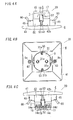
- the electric outlet 20 includes a pair of pin insertion holes 31a and 31a at its first face (front face).
- the pair of pin insertion holes 31a and 31a individually allow insertion of a pair of pins of a plug.
- first direction D1 a direction perpendicular to the first face
- the pins of the plug are pulled out from the pin insertion holes 31a and 31a.
- second side in the first direction D1 the pins of the plug are inserted into the pin insertion holes 31a and 31a.
- the first side in the first direction D1 is also referred to as "front side”
- the second side in the first direction D1 is also referred to as "rear side”.
- the electric outlet 20 includes a pair of blade receivers 6 and 7 to be connected to a first electric wire and a second electric wire (respectively corresponding to a line (hot) wire and a neutral wire) included in an electric cable.
- the blade receivers 6 and 7 are respectively provided on a first side and a second side of a second direction D2 perpendicular to the first direction D1 .
- the first side in the second direction D2 is also referred to as "left side”
- the second side in the second direction D2 is also referred to as "right side”.
- the electric outlet 20 of the embodiment includes a grounded member 5 to be connected to a third wire (grounding wire) corresponding to an earth (ground) wire of the electric cable, as an optional part.
- the grounded member 5 includes contact pieces 53 (531) and 53 (532), which extend forward, on a first side and a second side in a third direction D3 perpendicular to each of the first direction D1 and the second direction D2.
- the first side in the third direction D3 is also referred to as "upper side”
- the second side in the third direction D3 is also referred to as "lower side”.
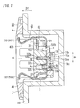
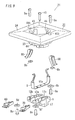
- the electric outlet 20 includes: a body 1 which has a box shape (a rectangular box shape in the present embodiment) and includes a front face having an opening 1a (see FIG. 3 ); a cover 2 which covers the front face of the body 1; and an assembling screw 10 which couples the body 1 and the cover 2 with each other.
- a body 1 which has a box shape (a rectangular box shape in the present embodiment) and includes a front face having an opening 1a (see FIG. 3 ); a cover 2 which covers the front face of the body 1; and an assembling screw 10 which couples the body 1 and the cover 2 with each other.
- the body 1 is made of thermosetting resin. Further, the body 1 includes two partition walls 11a and 11b (a first partition wall 11a provided on a left side, and a second partition wall 11b provided on a right side) which are protruded from an inner bottom face of the body 1 and are arranged side by side, and thus an inside space of the body 1 is separated into three compartments. In other words, three accommodation rooms 12 are formed inside the body 1.
- the three accommodation rooms 12 on the center, left, and right sides are referred to as a first accommodation room 12a, a second accommodation room 12b, and a third accommodation room 12c, respectively.
- the first accommodation room 12a is provided as a space between the two partition walls 11a and 11b.
- the first accommodation room 12a accommodates partially the grounded member 5 which is to be in contact with a pair of grounding electrodes 94 and 94 provided to a plug body 92 of a plug 91 (see FIG. 6 ).
- FIG. 6 shows one grounding electrode 94 of the pair of grounding electrodes 94 and 94.
- a rib 13 protruded from an inner bottom face of the first accommodation room 12a, and the rib 13 is used for positioning the grounded member 5.
- the first protrusion 19 protruding rearward from a rear surface (right surface in FIG. 1 ) of a bottom wall of the first accommodation room 12a.
- the first protrusion 19 has a cuboidal shape, for example.
- the first through hole 19a allows insertion of a tool (driver) for rotating a first terminal screw 8a for electrically and mechanically connecting a grounding wire (the third electric wire; not shown) to the grounded member 5.
- first recess 19b on a second end side (an upper end side in FIG. 1 ) of the first protrusion 19.
- the first recess 19b accommodates a head 10a of the assembling screw 10.
- the first insertion hole 19c allows insertion of a shank 10b of the assembling screw 10.
- the second accommodation room 12b is provided as a space between a side wall (first side wall) 27a on a left side of the body 1 (see FIG. 3 ) and the first partition wall 11a.
- the second accommodation room 12b accommodates a first blade reception spring 60 including the first blade receiver 6 for receiving a first pin 93 of a pair of pins 93 and 93 extending outside from the plug body 92.
- the second accommodation room 12b is connected to two electric wire insertion holes 14a and 14b.
- These electric wire insertion holes 14a and 14b are formed in a side wall (lower side wall) 28a on one side in a perpendicular direction perpendicular to a direction in which the two partition walls 11a and 11b are arranged side by side (the second side in the third direction D3).
- a first electric wire of an electric cable first electric cable
- this first electric wire can be electrically connected to the first blade reception spring 60 on the inner side of the hole.
- the first electric wire is corresponding to a neutral wire, for example.
- this first electric wire can be electrically connected to the first blade reception spring 60.
- the body 1 includes a side wall (an upper side wall) 29a which protrudes forward and is on another side (the first side in the third direction D3) in the perpendicular direction regarding the second accommodation room 12b.
- the second protrusion 15 protruding rearward from a center of a bottom wall of the second accommodation room 12b.
- the second protrusion 15 includes a first depressed part (not shown) for receiving an end of the first pin 93 of the pair of pins 93 and 93.
- the second through hole 16 is provided on a side (a lower side in FIG. 2B ) of the bottom wall of the second accommodation room 12b close to the electric wire insertion holes 14a and 14b.
- the second through hole 16 allows insertion of a tool (driver) for rotating a second terminal screw 8c for electrically and mechanically connecting an electric wire (the first electric wire of the first electrical cable or the first electric wire of the second electrical cable) to the first blade reception spring 60.
- the third accommodation room 12c is provided as a space between a further side wall (second side wall) 27b on a right side of the body 1 (see FIG. 3 ) and the second partition wall 11b .
- the third accommodation room 12c accommodates a second blade reception spring 70 including the second blade receiver 7 for receiving a second pin 93 of a pair of pins 93 and 93 extending outside from the plug body 92.
- the third accommodation room 12c is connected to two electric wire insertion holes 14c and 14d.
- These electric wire insertion holes 14c and 14d are formed in a side wall (lower side wall) 28b on one side in the perpendicular direction.
- this second electric wire can be electrically connected to the second blade reception spring 70 on the inner side of the hole.
- the second electric wire is corresponding to a line (hot) wire, for example.
- this second electric wire can be electrically connected to the second blade reception spring 70.
- the body 1 includes a side wall (an upper side wall) 29b which protrudes forward and is on a further side (the first side in the third direction D3) in the perpendicular direction regarding the third accommodation room 12c.
- the third protrusion 17 protruding rearward from a center of a bottom wall of the third accommodation room 12c.
- the third protrusion 17 includes a second depressed part (not shown) for receiving an end of the second pin 93 of the pair of pins 93 and 93.
- the third through hole 18 is provided on a side (the lower side in FIG. 2B ) of the bottom wall of the third accommodation room 12c close to the electric wire insertion holes 14c and 14d.
- the third through hole 18 allows insertion of a tool (driver) for rotating a third terminal screw 8e for electrically and mechanically connecting an electric wire (the second electric wire of the first electrical cable or the second electric wire of the second electrical cable) to the second blade reception spring 70.
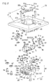
- the grounded member 5 has an inverted ⁇ shape, as shown in FIG. 3 .
- the grounded member 5 is made of metal.
- the grounded member 5 includes: a base end piece 51 with a plate shape; a pair of leg pieces 52 and 52 extending upright from opposite ends of the base end piece 51 ; and the contact pieces 53 provided to fore ends of the leg pieces 52 to be in contact with the grounding electrodes 94 of the plug 91 individually.
- the base end piece 51 includes at its center a second insertion hole 51a allowing insertion of the shank 10b of the assembling screw 10 .
- the base end piece 51 includes at its one end (upper right end in FIG. 3 ) a rib insertion hole 51b allowing insertion of the rib 13 protruded from the inner bottom surface of first accommodation room 12a.
- the base end piece 51 includes at its further end (lower left end in FIG. 3 ) a first screw insertion hole 51c allowing insertion of a shank of the first terminal screw 8a.
- the first nut 8b is to be engaged with the first terminal screw 8a. Note that, in the present embodiment, the first terminal screw 8a and the first nut 8b constitute a first screw terminal.
- the grounded member 5 (especially, the opposite ends thereof) is flexible, and the pair of contact pieces 53 and 53 are bent so that the foremost ends (front ends) thereof come close to each other.
- a distance between the contact pieces 53 and 53 is shorter than a distance between the pair of grounding electrodes 94 and 94 of the plug 91. Therefore, when the plug 91 is connected to the electric outlet 20, the top ends of the contact pieces 53 and 53 are biased to come close to each other by elastic force of the grounded member 5.
- Each contact piece 53 is smaller in width than the base end piece 51 and each leg 52.
- the first blade reception spring 60 is made of metal.
- the first blade reception spring 60 includes: a first terminal piece 61 with a plate shape (rectangular plate shape in the present embodiment) to be connected to one of the first electric wire of the first electric cable and the first electric wire of the second electric cable; a pair of side plates 62 and 62 protruding upright from opposite ends of the first terminal piece 61 ; and first spring pieces 64 and 64 extending from one ends (upper right ends in FIG. 3 ) of the pair of side plates 62 and 62 individually.
- the first spring pieces 64 and 64 constitute the first blade receiver 6 described above.
- the first terminal piece 61 includes a second screw insertion hole 61a allowing insertion of a shank of the second terminal screw 8c.
- the second nut 8d is to be engaged with the second terminal screw 8c. Note that, in the present embodiment, the second terminal screw 8c and the second nut 8d constitute a second screw terminal.
- first stopper 63 protruding upright on a side (upper right side in FIG. 3 ) of the first terminal piece 61 close to the first blade receiver 6.
- the first stopper 63 prevents excess insertion of one of the first electric wire of the first electric cable and the first electric wire of the second electric cable. Consequently, the electric outlet 20 of the present embodiment can prevent excess insertion of the electric wire, and therefore an insulation sheath (not shown) of the electric wire can be prevented from being caught in the second screw terminal. Thus, it is possible to avoid bad electrical connection between the first terminal piece 61 and a conductor (not shown) of the electric wire.
- the electric outlet 20 of the present embodiment can prevent excess insertion of the electric wire, and therefore it is possible to prevent insertion of the electric wire into the first blade receiver 6. Thus, it is possible to avoid bad electrical connection between the pin 93 of the plug 91 and the first blade receiver 6.
- the second blade reception spring 70 is made of metal.
- the second blade reception spring 70 includes: a second terminal piece 71 with a plate shape (rectangular plate shape in the present embodiment) to be connected to one of the second electric wire of the first electric cable and the second electric wire of the second electric cable; a pair of side plates 72 and 72 protruding upright from opposite ends of the second terminal piece 71; and second spring pieces 74 and 74 extending from one ends (upper right ends in FIG. 3 ) of the pair of side plates 72 and 72 individually.
- the second spring pieces 74 and 74 constitute the second blade receiver 7 described above.
- the second terminal piece 71 includes a third screw insertion hole 71a allowing insertion of a shank of the third terminal screw 8e.
- the third nut 8f is to be engaged with the third terminal screw 8e. Note that, in the present embodiment, the third terminal screw 8e and the third nut 8f constitute a third screw terminal.
- the second stopper 73 protruding upright on a side (upper right side in FIG. 3 ) of the second terminal piece 71 close to the second blade receiver 7.
- the second stopper 73 prevents excess insertion of one of the second electric wire of the first electric cable and the second electric wire of the second electric cable. Consequently, the electric outlet 20 of the present embodiment can prevent excess insertion of the electric wire, and therefore an insulation sheath (not shown) of the electric wire can be prevented from being caught in the third screw terminal.
- the electric outlet 20 of the present embodiment can prevent excess insertion of the electric wire, and therefore it is possible to prevent insertion of the electric wire into the second blade receiver 7. Thus, it is possible to avoid bad electrical connection between the pin 93 of the plug 91 and the second blade receiver 7.
- the cover 2 is constituted by a first cover 3 made of thermosetting resin and a second cover 4 made of thermoplastic resin.
- the first cover 3 includes a body part 31 having a plate shape.
- a shape of the body part 31 in a plan view is an ellipsoidal shape.
- This body part 31 covers the front face of the body 1.
- the body part 31 includes the pair of pin insertion holes 31a and 31a individually allowing insertion of the pair of pins 93 and 93 of the plug 91.
- the pair of pin insertion holes 31a and 31a are arranged in a width direction (the second direction D2) of the body part 31 and are positioned in a center in a length direction (the third direction D3) of the body part 31.
- the two exposing cuts 31b and 31b expose the two contact pieces 53 and 53 of the grounded member 5 on the front face (upper face in FIG. 3 ) of the body part 31 individually.
- a fourth protrusion 32 protruding rearward from a rear face (lower face in FIG. 3 ) of the body part 31 between the pair of pin insertion holes 31a and 31a.
- the fourth protrusion 32 is accommodated in the first accommodation room 12a of the body 1 so as to be in contact with the base end piece 51 of the grounded member 5 (see
- FIG. 1 1).
- the fourth protrusion 32 includes, at a portion facing the second insertion hole 51a of the grounded member 5, a screw hole 32a to receive the assembling screw 10.
- the screw hole 32a is formed in the rear face side of the first cover 3.
- the fourth protrusion 32 includes, at a portion facing the first screw insertion hole 51c of the grounded member 5, a second recess 32b for accommodating the first nut 8b.
- the second cover 4 includes an accommodation part 42 and a plate 41 in the form of a frame.
- the accommodation part 42 protrudes rearward from a rear side face of the second cover 4 to form a cylindrical recess with a bottom 42a which includes a hole (window hole 42c).
- the first cover 3 is accommodated in the accommodation part 42 so that the body part 31 covers the hole of the bottom 42a.
- the plate 41 extends laterally from a side part 42b close to an opening of the accommodation part 42. Note that, an outer peripheral shape of the plate 41 is a rectangular shape as shown in FIG. 3 , but is not limited particularly.
- the accommodation part 42 has a shape of a hollow cylinder with a bottom, for example. Further, a shape of the opening of the accommodation part 42 is a circular shape but is not limited particularly, and may be preferably suitable for the shape of the plug body 92 in a plan view. In this regard, in the present embodiment, the shape of the plug body 92 in a plan view is a circular shape.
- the bottom 42a (see FIG. 1 ) of the accommodation part 42 is held between the body part 31 of the first cover 3 and the body 1. This bottom 42a includes the window hole 42c which allows insertion of part of the body part 31 around the pair of pin insertion holes 31a and 31a and is larger in size than each of the pin insertion holes 31a and 31a.
- FIG. 6 shows only one elongated part 95 of the pair of elongated parts 95 and 95.
- each slit 44 has an L shape to extending across the bottom 42a and the side part 42b of the accommodation part 42 (see FIG. 2A ). Therefore, in the electric outlet 20 of the present embodiment, the pair of contact pieces 53 and 53 can be drawn into the inside of the accommodation part 42 via the pair of slits 44 and 44. Consequently, the electric outlet 20 of the present embodiment allows the pair of contact pieces 53 and 53 to be in contact with the pair of grounding electrodes 94 and 94 of the plug body 92 individually when the plug body 92 of the plug 91 is fitted into the accommodation part 42.
- the first terminal screw 8a is inserted into the first screw insertion hole 51c of the base end piece 51 of the grounded member 5 from the rear face side (right side in FIG. 1 ) of the base end piece 51, and then the first nut 8b is screwed on this first terminal screw 8a.
- the grounded member 5 is accommodated in the first accommodation room 12a of the body 1 so that the rib 13 of the body 1 is inserted in the rib insertion hole 51b of the grounded member 5 and the head of the first terminal screw 8a is situated in front (in FIG. 1 , at the left) of the first through hole 19a of the body 1.
- the second terminal screw 8c is inserted into the second screw insertion hole 61a of the first terminal piece 61 of the first blade reception spring 60 from the rear face side (lower side in FIG. 3 ) of the first terminal piece 61, and the second nut 8d is screwed on this second terminal screw 8c. Thereafter, the first blade reception spring 60 is accommodated in the second accommodation room 12b of the body 1 so that the head of the second terminal screw 8c is positioned in front of the second through hole 16 of the body 1.
- the third terminal screw 8e is inserted into the third screw insertion hole 71a of the second terminal piece 71 of the second blade reception spring 70 from the rear face side (lower side in FIG. 3 ) of the second terminal piece 71, and the third nut 8f is screwed on this third terminal screw 8e. Thereafter, the second blade reception spring 70 is accommodated in the third accommodation room 12c of the body 1 so that the head of the third terminal screw 8e is positioned in front of the third through hole 18 of the body 1.
- the pair of contact pieces 53 and 53 of the grounded member 5 are drawn into the inside of the accommodation part 42 via the pair of slits 44 and 44 of the second cover 4, and the second cover 4 is situated on the front face of the body 1.
- the first cover 3 is accommodated in the accommodation part 42 of the second cover 4 so that the pair of contact pieces 53 and 53 which are drawn into the inside of the accommodation part 42 of the second cover 4 are exposed through the pair of exposing cuts 31b and 31b of the first cover 3.
- the fourth protrusion 32 of the first cover 3 is made to protrude rearward (to the right in FIG. 1 ) through the window hole 42c of the second cover 4.
- the assembling screw 10 is inserted into the first insertion hole 19c of the body 1 and the second insertion hole 51a of the grounded member 5 from the rear surface of the body 1, and then is screwed into the screw hole 32a of the fourth protrusion 32 of the first cover 3.
- the bottom 42a of the accommodation part 42 of the second cover 4 is held between the body part 31 of the first cover 3 and the body 1, and thereby the electric outlet 20 can be assembled.
- the plate 41 includes multiple (two in the present embodiment) first attachment screw insertion holes 41b allowing insertion of attachment screws 9a for attaching the attachment metal parts 80 to the plate 41.
- the attachment metal part 80 includes: a base end piece 81 in the form of a plate shape; a pair of leg pieces 82 and 82 protruding upright from opposite ends of the base end piece 81; and claws 83 formed on fore ends of the leg pieces 82.
- the base end piece 81 includes at its center a second attachment screw insertion hole 81a allowing insertion of the attachment screw 9a.
- the embedded box 90 is assumed to have a shape of a rectangular box having a front face including an opening. Further, in the following description of the present embodiment, the embedded box 90 is assumed to be made of synthetic resin (e.g., thermosetting resin), for example.
- synthetic resin e.g., thermosetting resin
- each attachment screw 9a is inserted into the first attachment screw insertion hole 41b and the second attachment screw insertion hole 81a of the attachment metal part 80 from the front side (upper side in FIG. 3 ) of the second cover 4, and is temporarily fixed to the fourth nut 9b.
- each attachment metal part 80 is temporarily fixed to the second cover 4.
- the attachment screws 9a are tightened with the fourth nuts 9b individually.
- the claws 83 of each of the attachment metal parts 80 can bite in the inner surface of the embedded box 90, and thereby the electric outlet 20 can be attached to the embedded box 90.
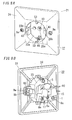
- FIG. 7 to FIG. 9 show a configuration of an electric outlet of a comparative example.
- the electric outlet 21 of this comparative example includes a body 1, a grounded member 5, a first blade reception spring 60, and a second blade reception spring 70.
- the electric outlet 21 of the comparative example includes a cover 22 which covers a front face (upper face in FIG. 9 ) of the body 1.
- components of the electric outlet 21 of the comparative example which are the same as the components of the electric outlet 20 of the present embodiment are designated by the same reference signs as the electric outlet 20 of the present embodiment.
- the cover 22 is made of thermosetting resin. Further, the cover 22 includes a cover body 23 having a shape of a hollow cylinder with a bottom, and a flange 24 which is square in a plan view and extends laterally from a side part of the cover body 23 close to an opening of the cover body 23.
- the cover body 23 includes a bottom 23a (see FIG. 8A ), and a pair of pin insertion holes 23b and 23b individually allowing insertion of the pair of pins 93 and 93 of the plug 91 are formed in the bottom 23a.
- an accommodation recessed part 26 for accommodating a head 10a of an assembling screw 10 for coupling the cover 22 and the body 1 is provided to a center of a bottom 23a of the cover body 23.
- a third insertion hole 26b (see FIG. 7 ) allowing insertion of a shank 10b of the assembling screw 10 is formed to penetrate the bottom of the accommodation recessed part 26.
- a screw hole 25 for being screwed on the assembling screw 10 is formed in a part of the bottom wall of a first accommodation room 12a of the body 1 facing the third insertion hole 26b of the accommodation recessed part 26 of the cover body 23.
- attachment metal parts 80 are provided to the flange 24.
- the assembling screw 10 is inserted into the third insertion hole 26b of the accommodation recessed part 26 of the cover body 23 and a second insertion hole 51a of a grounded member 5 from the front face side (upper side in FIG. 9 ) of the cover 22, and is screwed into the screw hole 25 of the first accommodation room 12a of the body 1.
- the electric outlet 21 can be assembled.
- the cover 22 is made of thermosetting resin. Therefore, compared with a case where the cover 22 is made of thermoplastic resin, it may take more time to form the cover 22.
- the cover 2 is constituted by the first cover 3 and the second cover 4, and the second cover 4 is made of thermoplastic resin which is higher in formability than thermosetting resin. Therefore, compared with the electric outlet 21 of the comparative example, it makes possible to improve the formability of the cover 2.
- the assembling screw 10 is exposed on the front face side of the cover 22. Therefore, when a person erroneously detaches the assembling screw 10 while the electric outlet 21 is attached to the embedded box 90, the cover 22 and the body 1 may be separated from each other.
- the head 10a of the assembling screw 10 is situated on the rear face side of the bottom wall of the body 1, and therefore the assembling screw 10 is not exposed on the front face side of the cover 2.
- the assembling screw 10 is not exposed on the front face side of the cover 2, and therefore designability can be improved compared with the electric outlet 21 of the comparative example.
- the electric outlet 20 of the aforementioned present embodiment includes: the body 1 which has a box shape and includes the front face having the opening 1a; the cover 2 which covers the front face of the body 1; and the assembling screw 10 which couples the body 1 and the cover 2 with each other.
- the cover 2 is constituted by the first cover 3 made of thermosetting resin, and the second cover 4 made of thermoplastic resin.
- the first cover 3 includes the body part 31 which has a plate shape and includes a pair of pin insertion holes 31a and 31a individually allowing insertion of the pair of pins 93 and 93 of the plug 91.
- the second cover 4 includes the accommodation part 42 which has a hollow cylindrical shape with a bottom and accommodates the body part 31.
- the bottom 42a of the accommodation part 42 is held between the body part 31 and the body 1 and the bottom 42a includes the window hole 42c which allows insertion of the pair of pins 93 and 93 and is larger in size than each of the pair of pin insertion holes 31a.
- the body 1 accommodates the pair of blade receivers 6 and 7 configured to individually receive the pair of pins 93 and 93.
- the assembling screw 10 includes the head 10a positioned on the rear face side of the bottom wall of the body 1 and the shank 10b inserted in the insertion hole (the first insertion hole) 19c of the bottom wall of the body 1, and the shank 10b includes the end screwed in the screw hole 32a in the rear face side of the body part 31.
- the formability of the cover 2 can be improved, and it is possible to avoid careless detachment of the assembling screw 10.
- the assembling screw 10 is not exposed on the front face side of the cover 2. Therefore, in contrast to the conventional embedded electric outlet having the configuration shown in FIG. 10 and the electric outlet 21 of the comparative example, the designability can be improved.
- the through hole (the first insertion hole 19c) for insertion of the assembling screw 10 is provided to the body 1 accommodating the blade receivers 6 and 7. Further, the screw hole 32a for being screwed on the assembling screw 10 is provided to the rear face of the first cover 3 (the cover 2) so as not to penetrate through the first cover 3.
- the second cover 4 includes the accommodation part 42 which is hollow cylindrical and includes the bottom provided with the hole (the window hole 42c).
- the first cover 3 includes the body part 31 having a plate shape, and the body part 31 is accommodated in the accommodation part 42 so as to close the hole (the window hole 42c) of the accommodation part 42.
- the first cover 3 includes the protrusion (the fourth protrusion 32) protruding rearward, and the screw hole 32a is formed in the rear face side of this protrusion.
- the body 1 includes the side walls (27a, 27b, 28a, 28b, 29a, and 29b) protruding forward.
- the bottom 42a of the accommodation part 42 is held between the body part 31 of the first cover 3 and at least one of these side walls. Note that, in the electric outlet 20 of the present embodiment, the blade receivers (the first blade receiver 6, the second blade receiver 7) are accommodated in the accommodation room (the second accommodation room 12b, the third accommodation room 12c) surrounded by the multiple side walls.
- the second cover 4 is made of thermosetting resin.
- the second cover 4 may be made of thermoplastic resin.
- the formability of the cover can be improved.
- the plug 91 includes, as first and second male connectors, two pins 93 and 93 corresponding to line (hot) and neutral wires individually.
- a plug suitable for the electric outlet of the present invention is not limited to including the aforementioned ones.
- a plug suitable for the electric outlet of the present invention is not limited to a plug with two round pins such as the BS4573 plug, the CEE7/4 plug, the CEE7/5 plug, the CEE7/17 plug, the 107-2-D1 plug, the CEI23-16/VII plug, the SEV1011 plug, the IEC60906-1 plug, and the TIS166-2549 plug.
- a plug suitable for the electric outlet of the present invention may include, as first and second male connectors, two blades having thickness directions parallel to the second direction D2 as with the JIS C 8303 plug, the NEMA1-15 plug, or the NEMA5-15 plug, or two blades having thickness directions parallel to the third direction D3 as with the BS1363 plug, or two V-shaped or inverted V-shaped blades as with the CPCS-CCC plug or the AS/NZS3112 plug.
- the plug 91 includes the grounding electrodes 94 and 94 as a ground connector (option).
- a plug suitable for the electric outlet of the present invention is not limited to including the aforementioned ones.
- a plug suitable for the electric outlet of the present invention may include, as a ground connector, a grounding pin which has a U-shaped section or has a hollow cylindrical shape, or a grounding blade as with the AS/NZS3112 plug or the BS1363 plug, or a half-round grounding pin as with the 107-2-D1 plug, or a round grounding pin as with the CEI23-16/VII plug, the SEV1011 plug, the NEMA5-15 plug, or the TIS166-2549 plug.
- the electric outlet of the present invention may be an electric outlet configured to be connected to any of various types of plugs described above.
Landscapes
- Connector Housings Or Holding Contact Members (AREA)
Applications Claiming Priority (2)
| Application Number | Priority Date | Filing Date | Title |
|---|---|---|---|
| JP2012203328A JP5958859B2 (ja) | 2012-09-14 | 2012-09-14 | コンセント |
| PCT/JP2013/004918 WO2014041747A1 (ja) | 2012-09-14 | 2013-08-20 | コンセント |
Publications (2)
| Publication Number | Publication Date |
|---|---|
| EP2897232A1 true EP2897232A1 (de) | 2015-07-22 |
| EP2897232A4 EP2897232A4 (de) | 2015-09-09 |
Family
ID=50277892
Family Applications (1)
| Application Number | Title | Priority Date | Filing Date |
|---|---|---|---|
| EP13837772.6A Withdrawn EP2897232A4 (de) | 2012-09-14 | 2013-08-20 | Elektrische steckdose |
Country Status (3)
| Country | Link |
|---|---|
| EP (1) | EP2897232A4 (de) |
| JP (1) | JP5958859B2 (de) |
| WO (1) | WO2014041747A1 (de) |
Cited By (2)
| Publication number | Priority date | Publication date | Assignee | Title |
|---|---|---|---|---|
| WO2021229469A1 (de) * | 2020-05-12 | 2021-11-18 | Carmelo Militello | Steckerbuchse für wasserdichte anwendungen |
| WO2023103845A1 (zh) * | 2021-12-10 | 2023-06-15 | 王军 | 一种便携插座 |
Families Citing this family (1)
| Publication number | Priority date | Publication date | Assignee | Title |
|---|---|---|---|---|
| KR200489967Y1 (ko) * | 2018-07-24 | 2019-09-02 | 만 석 김 | 소켓의 환상의 안내두부가 형성된 어스 접속편 |
Family Cites Families (3)
| Publication number | Priority date | Publication date | Assignee | Title |
|---|---|---|---|---|
| JP3546677B2 (ja) * | 1997-12-22 | 2004-07-28 | 松下電工株式会社 | コンセント |
| JP3932931B2 (ja) | 2002-02-25 | 2007-06-20 | 松下電工株式会社 | 埋込型コンセント |
| JP5185863B2 (ja) * | 2009-03-24 | 2013-04-17 | パナソニック株式会社 | コンセント |
-
2012
- 2012-09-14 JP JP2012203328A patent/JP5958859B2/ja not_active Expired - Fee Related
-
2013
- 2013-08-20 EP EP13837772.6A patent/EP2897232A4/de not_active Withdrawn
- 2013-08-20 WO PCT/JP2013/004918 patent/WO2014041747A1/ja not_active Ceased
Cited By (2)
| Publication number | Priority date | Publication date | Assignee | Title |
|---|---|---|---|---|
| WO2021229469A1 (de) * | 2020-05-12 | 2021-11-18 | Carmelo Militello | Steckerbuchse für wasserdichte anwendungen |
| WO2023103845A1 (zh) * | 2021-12-10 | 2023-06-15 | 王军 | 一种便携插座 |
Also Published As
| Publication number | Publication date |
|---|---|
| WO2014041747A1 (ja) | 2014-03-20 |
| EP2897232A4 (de) | 2015-09-09 |
| JP5958859B2 (ja) | 2016-08-02 |
| JP2014059995A (ja) | 2014-04-03 |
Similar Documents
| Publication | Publication Date | Title |
|---|---|---|
| KR101673924B1 (ko) | 커넥터 및 커넥터 조립체 | |
| JP6061148B2 (ja) | コネクタ | |
| EP2701245A2 (de) | Steckverbinder und Produktionsverfahren dafür | |
| US7740484B1 (en) | Rotatable receptacle | |
| JP4314589B2 (ja) | 多極同軸コネクタ | |
| US20170077632A1 (en) | Electrical connector | |
| JP2010267548A (ja) | 電気コネクタ | |
| JP5341532B2 (ja) | 1対の誤嵌合防止キー及び該キーを用いた電気コネクタ | |
| EP3783748A1 (de) | Verbinder | |
| CN105531880A (zh) | 电缆保持构件、电连接装置、连接器装置、扁平电缆 | |
| US10553979B2 (en) | Connector | |
| US5529506A (en) | Terminal for shielding connectors and shielding connector | |
| WO2014125541A1 (ja) | Usbコンセント | |
| US8272894B2 (en) | Coaxial connector | |
| US8834206B2 (en) | Electrical connector with grounging plate | |
| US10256574B2 (en) | Connector and shielding shell | |
| EP2897232A1 (de) | Elektrische steckdose | |
| KR200417442Y1 (ko) | 조인트 커넥터 | |
| KR200457984Y1 (ko) | 암수 커넥터 | |
| CN109038114B (zh) | 屏蔽罩和屏蔽连接器 | |
| US8251709B2 (en) | Electrical connector with improved cable fixation | |
| JP2011113678A (ja) | フラットケーブル用コネクタ及びその組立方法 | |
| JP6032596B2 (ja) | 端子装置およびそれを用いたコンセント | |
| KR20210039104A (ko) | 고전압 커넥터 및 이를 조립하는 방법 | |
| US9590322B2 (en) | Connector |
Legal Events
| Date | Code | Title | Description |
|---|---|---|---|
| PUAI | Public reference made under article 153(3) epc to a published international application that has entered the european phase |
Free format text: ORIGINAL CODE: 0009012 |
|
| 17P | Request for examination filed |
Effective date: 20150204 |
|
| AK | Designated contracting states |
Kind code of ref document: A1 Designated state(s): AL AT BE BG CH CY CZ DE DK EE ES FI FR GB GR HR HU IE IS IT LI LT LU LV MC MK MT NL NO PL PT RO RS SE SI SK SM TR |
|
| AX | Request for extension of the european patent |
Extension state: BA ME |
|
| RA4 | Supplementary search report drawn up and despatched (corrected) |
Effective date: 20150812 |
|
| RIC1 | Information provided on ipc code assigned before grant |
Ipc: H01R 13/502 20060101AFI20150806BHEP Ipc: H01R 13/512 20060101ALI20150806BHEP Ipc: H01R 103/00 20060101ALN20150806BHEP Ipc: H01R 13/46 20060101ALI20150806BHEP Ipc: H01R 24/78 20110101ALI20150806BHEP |
|
| DAX | Request for extension of the european patent (deleted) | ||
| RIC1 | Information provided on ipc code assigned before grant |
Ipc: H01R 13/512 20060101ALI20170928BHEP Ipc: H01R 13/502 20060101AFI20170928BHEP Ipc: H01R 13/46 20060101ALI20170928BHEP Ipc: H01R 24/78 20110101ALI20170928BHEP Ipc: H01R 103/00 20060101ALN20170928BHEP |
|
| GRAP | Despatch of communication of intention to grant a patent |
Free format text: ORIGINAL CODE: EPIDOSNIGR1 |
|
| INTG | Intention to grant announced |
Effective date: 20171121 |
|
| STAA | Information on the status of an ep patent application or granted ep patent |
Free format text: STATUS: THE APPLICATION IS DEEMED TO BE WITHDRAWN |
|
| 18D | Application deemed to be withdrawn |
Effective date: 20180404 |